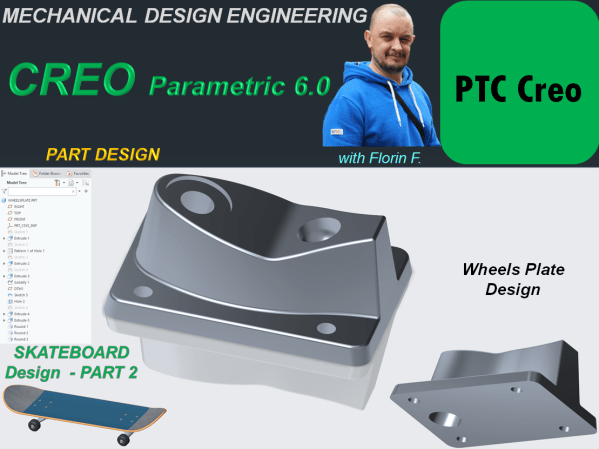
The plate design for wheels of a Skateboard done in CREO parametric goes as follows: STEP 1. Create a New part and rename it WheelsPlate STEP 2. Click on Extrude icon and use the Sketch option from far upper right in Extrude window to create a center rectangle of 55x80 on the Top Plane and... Continue Reading →
CREO PARAMETRIC 6.0 – SKATEBOARD DESIGN_Part 1 – Board Design
This is Part 1 of the design work for Skatebord product. As usual I start this work by designing each component and later I will generate the final product assembly. The first component is the BOARD. STEP 1. Create a new part and rename it "Board" STEP 2. In Model Workbench click on Sweep icon... Continue Reading →
SOLIDWORKS – Pirate Ship Wheel Design
Let's design a Pirate Ship Wheel STEP 1. Create a new CAD file STEP 2. On Right Plane, sketch the 2 profiles for outer and inner wheel at a distance from each other of 360mm as shown: STEP 3. In the Features toolbar, click on Revolved Boss/Base icon and revole everithing completelly. STEP 4. On... Continue Reading →
SOLIDWORKS – Thor Hammer Design
Let's Design the Thor Hammer with SOLIDWORKS PART 1 - Handle STEP 1. Create New Part STEP 2. On the Right Plane draw the sketch as shown: STEP 3. In Featrues toolbar, click on Revolved Boss/Base icon and revolve the sketch completely. STEP 4. On Top Plane create a sketch as shown: STEP 5. In... Continue Reading →
SOLIDWORKS_Toothbrush Design
Let´s design a toothbrush with SOLIDWORKS STEP 1. Create a New Part. Save the part with a new name as: Toothbrush and while you advance with the design work from time to time, don´t forget to click the Save icon. STEP 2. In the drawing view or from the model tree select the Front Plane... Continue Reading →
MECHANICAL DESIGN ENGINEERING – Geometrical Dimensioning and Tolerancing_What is the POSITION tolerance?
Location tolerances determine the nominal location or ideal location of a feature relative to one or more references. This results in 3 types: Position: the nominal location is determined by theoretical dimensions Coaxiality/Concentricity :The nominal location is the axis or the center of the reference element Symmetry: The nominal location is the median plane or... Continue Reading →
MECHANICAL DESIGN ENGINEERING – Geometrical Dimensioning and Tolerancing_What is the ANGULARITY tolerance?
Objects made as an assembly of more than 1 component, in order to be functional besides a clearly specified form each component, must have at least 1 clearly specified orientation (parallel, perpendicular or angular). For the parallelism and perpendicularity the orientation is quite simple to understand , it is either at 0° or at 90°,... Continue Reading →
CREO PARAMETRIC 6.0 – INTERACTIVE SURFACE DESIGN_Baby Car Seat
Working with CAD software to create new products is a huge improvement in the modern design process versus the old times when the work had to be done simply by hand. The posibilities to do mechanical design today are way much better. A new product can be created with any of these CAD platforms available... Continue Reading →
CREO PARAMETRIC 6.0 – FREESTYLE DESIGN_Apple Earbud
There are many objects which are commercially succesful if their design make them look attractive. Such example of products are those made by Apple. They use a lot of Freestyle design and one example here is the already well known Wireless Earbud. In this post I am showing you how this product can be designed... Continue Reading →
CATIA V5 – GENERATIVE SHAPE DESIGN – Bike saddle design
Generative Shape Design Workbench is an interactive environment and it works perfectly in combination with Part Design Workbench. Therefore to explore a bit more in details how does GDS works, let´s create a part which is only possible with GSD, such as a Bike Saddle. The most easier workbench to work with in any CAD... Continue Reading →