A wheel rim design can be done in different ways, depending on the wanted pattern and the used CAD software. In this example I show you a version of Wheel Rim used on AUDI cars and how to do it in CREO Parametric CAD software. A wheel rim can also be done in 1 piece... Continue Reading →
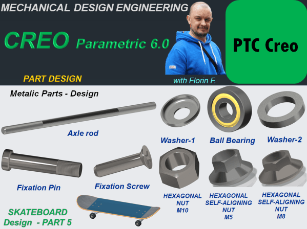
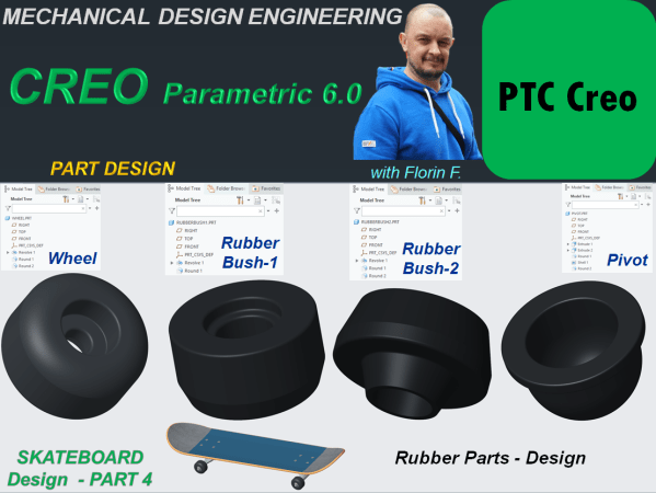
CREO PARAMETRIC 6.0 – Audi Wheel Rim Design