Description Definition: Total Runout is how much one entire feature or surface varies with respect to a datum when the part is rotated 360° around the datum axis. Total runout controls both the amount of variation in the surface as the part is rotated, but the amount of variation in the axial dimension. Both radial... Continue Reading →
MECHANICAL DESIGN ENGINEERING – Geometrical Dimensioning and Tolerancing_What is the CIRCULAR RUNOUT tolerance?
Runout is one of the oldest and simplest concepts used in GD & T. Maybe as a child you stood your bicycle upside down on the ground and spun a wheel. If you fixed your stare on the shiny rim where it passed a certain part of the frame, you could see the rim wobble... Continue Reading →
SOLIDWORKS_Viking Helmet
In this post I'll show you how to design a Viking Helmet made of 2 main componets :The Helmet Body and the Horn Body, which will make the final assembly in a Viking Helmet Product. Let's start with The Helmet!! THE HELMET STEP 1 Create new part STEP 2 Create 2 reference planes, each at... Continue Reading →
MECHANICAL DESIGN ENGINEERING – Geometrical Dimensioning and Tolerancing_What is the SYMMETRY tolerance?
Among the 14 used GD & T symbols in the category of Location Tolerances there are 3 types. 1. The Position Tolerance 2. The Concentricity Tolerance 3. The Symmetry Tolerance From these 3 tolerance types, only the Position Tolerance is often used as it is also easy to measure. The other 2 are in general... Continue Reading →
MECHANICAL DESIGN ENGINEERING – Geometrical Dimensioning and Tolerancing_What is the CONCENTRICITY tolerance?
The functionality of a part in an assembly is usually well defined by the 4 form tolerances (straigthness, flatness, circularity and cylindricity) and among the orientation tolerances by the 3 most frequent ones: the position, the perpendicularity and the parallelism tolerance. Yet we have 14 different types of tolerances in total, which can be anytime... Continue Reading →
CREO PARAMETRIC 6.0 – Audi Wheel Rim Design
A wheel rim design can be done in different ways, depending on the wanted pattern and the used CAD software. In this example I show you a version of Wheel Rim used on AUDI cars and how to do it in CREO Parametric CAD software. A wheel rim can also be done in 1 piece... Continue Reading →
SOLIDWORKS – Bug Rover _ Part 4 – Assembly Design
As we've already seen in the previous posts, The Bug Rover is made of various components. In this post we'll put everything together in the final product. But before to create the final assembly, let's create first the Sub-Assembly called Carterpilar which will be later used as multiple instances for the final assembly. Let's start:... Continue Reading →
SOLIDWORKS – Bug Rover _ Part 3 – Carterpilar Design
In this Part of Bug Rover design work, I'll show you the 3 main components of the Carterpilar assembly. These are: The Star Gear, The Gear Cap, The Wheel and The Carterpillar. Let's start: THE STAR GEAR STEP 1 Create a new part STEP 2 On Front plane draw the following sketch and revolve it... Continue Reading →
SOLIDWORKS – Bug Rover _ Part 2 – Lever Design
In this 2nd part of design work for the Bug Rover, I'll show you the next 2 main components: The Lever and The Lever Cap. Let's start: THE LEVER STEP 1 Create new part STEP 2 Create the following 2 sketches: STEP 3 Use the previous 2 sketches to create a Project Curve STEP 4... Continue Reading →
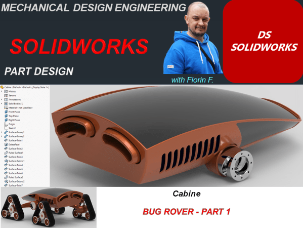
SOLIDWORKS – Bug Rover _ Part 1 – Cabine Design
A rover design work implies a lot of details and components. In this article I want to present you a simplified version of a reover concept I did, which is inspired from the insects world. It really looks like a bug, so I name it Bug Rover. I will only put here the main bodies... Continue Reading →


