
Working with CAD software to create new products is a huge improvement in the modern design process versus the old times when the work had to be done simply by hand. The posibilities to do mechanical design today are way much better. A new product can be created with any of these CAD platforms available but the stategy to follow is each time quite different from one CAD software to another. In this post I wish to show you my approach for doing such design work with the powerful CREO Parametric software. Like other similar design software CREO gives you the opportunity to design prodcuts with irregular surfaces. The specific name for this environment is called Interactive Surface Design Extension or in short ISDX.
Therefore let’s create a baby car seat product where we’ll explore some of the capabilities of ISDX interface in CREO Parametric 6.0.
COMPONENT 1 – Baby Car Seat_Main Body
STEP 1.
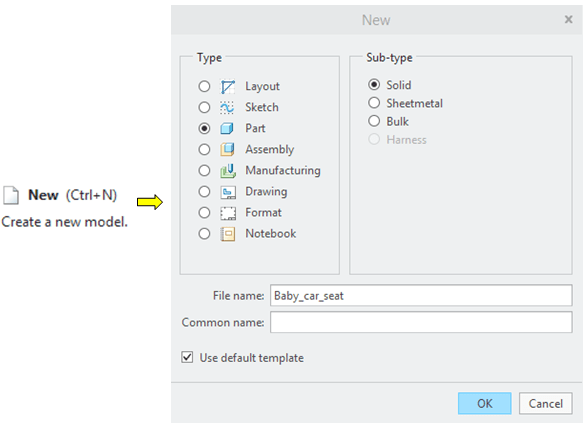
Create New part
STEP 2.
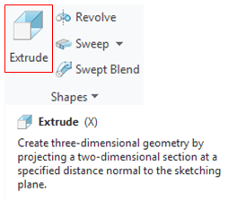
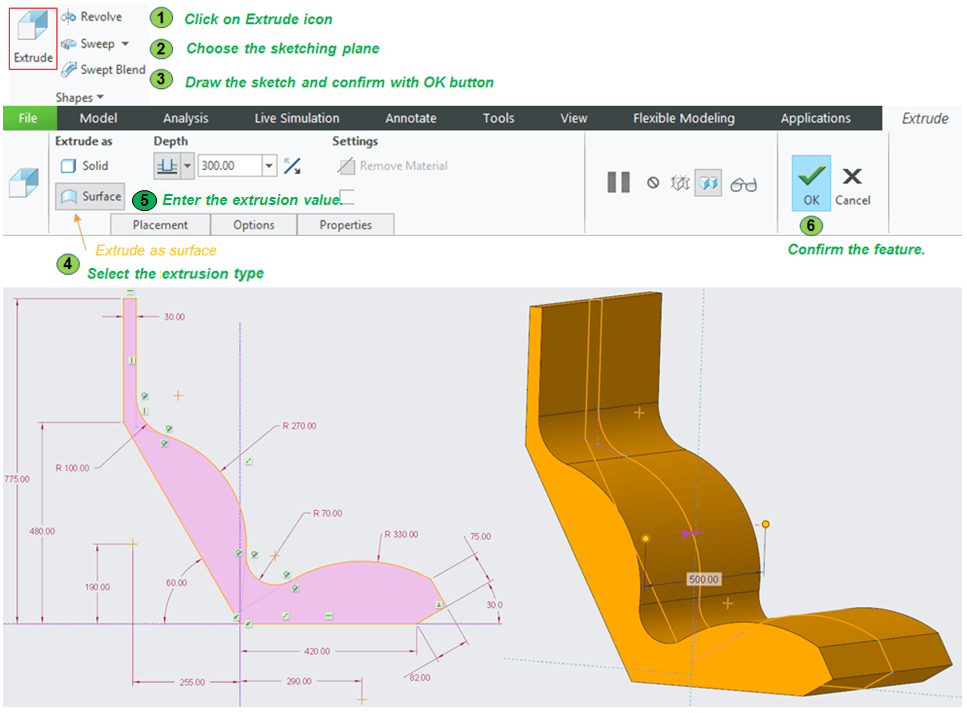
Select the FRONT datum plane and create the 1st feature as an Extrude.
In sketch environment, create a profile as shown and extrude it symmetrically at 500mm length.
Note: the result must be a closed profile fully constrained. A good strategy in this case is to start drawing and constraining first the lines, then second add the necessary arcs/circles, define their position and trim the unnecessary curves. (see how I did this in the video on my You Tube embedded at the end of this description).
STEP 3.
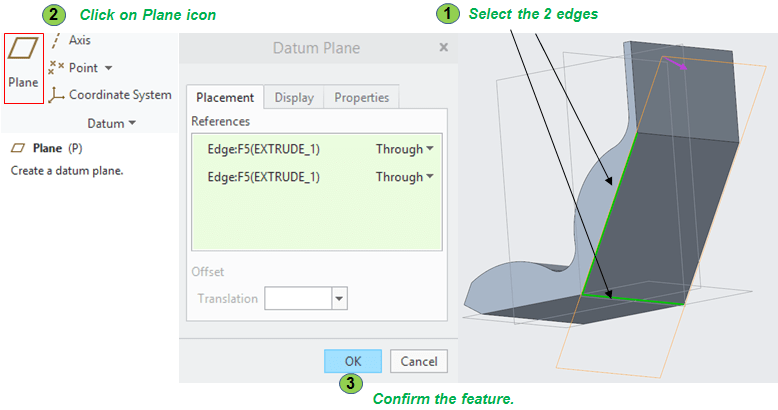
Next, before to continue adding definition features, you need to create some construction elements. For now, create 3 new datum planes (DTM). Do the 1st plane as follows:
STEP 4.
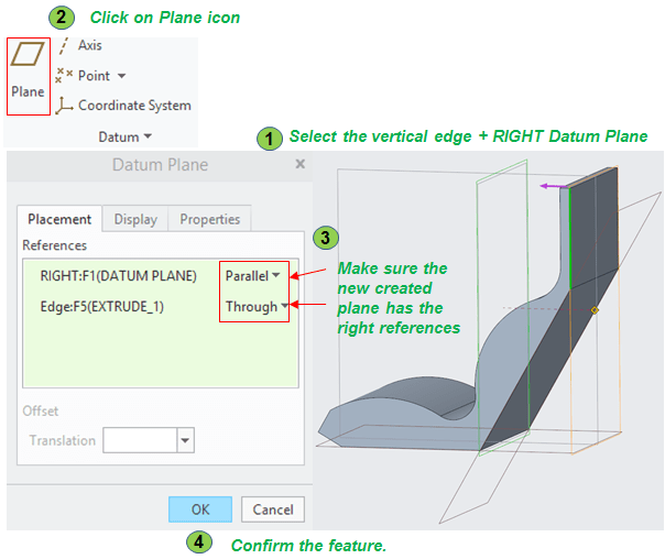
Create the 2nd New datum plane
STEP 5.

Create the 3rd datum plane.
STEP 6.
You also need 3 construction sketches to help you define the surface that will generate the outer shape of the final product. You can either select and sketch on the available planes on each side or you can directly select the planar surface and sketch on it, then do the following sketches:
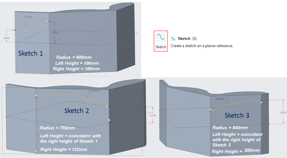
STEP 7.
Now let’s create the first surface feature. Working with irregular surfaces might be a little bit more accurate than just with regular features. So pay attention how you continue, mainly when you deal with points and tangent lines defined in coordinates related to a irregular surface.
Using the 3 previous construction sketches, in the Surfaces Group click on Style icon to enter in Style environment and continue the process as follows:
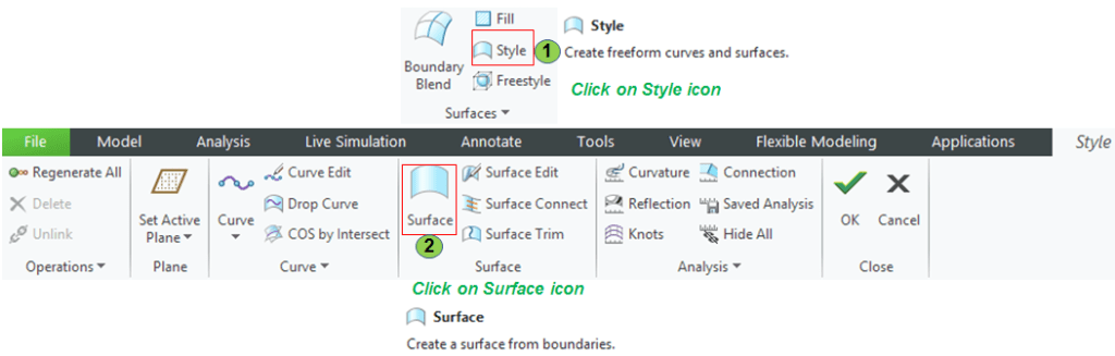

STEP 8.
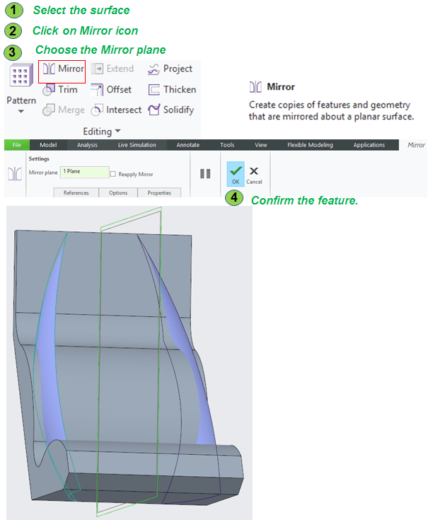
The same surface from the previous step will define the shape of the final part on both sides (left & right), so for this no need to create another surface as previously done. You can simply mirror the existing one with the middle plane.
STEP 9.
With the 2 surrfaces on both sides available you can easily notice that they don’t completelly cut through the solid. So they need to be extended. For both surfaces just proceed as follows:

STEP 10.
Now the solid is ready to be trimmed. Do this on both sides.
STEP 11.
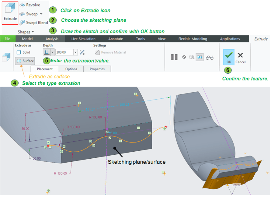
On the front bottom side the solid must be also trimmed but in this case the surface can be created directly in the Model environment using the Extrude feature.
STEP 12.
Similary with the sides, the solid is now ready to be trimmed on the front bottom as well.
STEP 13.
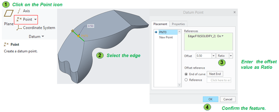
For the backside, a new curved surface, a sort of bulge must be created within the Style Environment. But before to do that, youneed new constuction elements such as points, axis and planes. Start with the points. Create a point on the lower and upper edges on the backside as folollows:
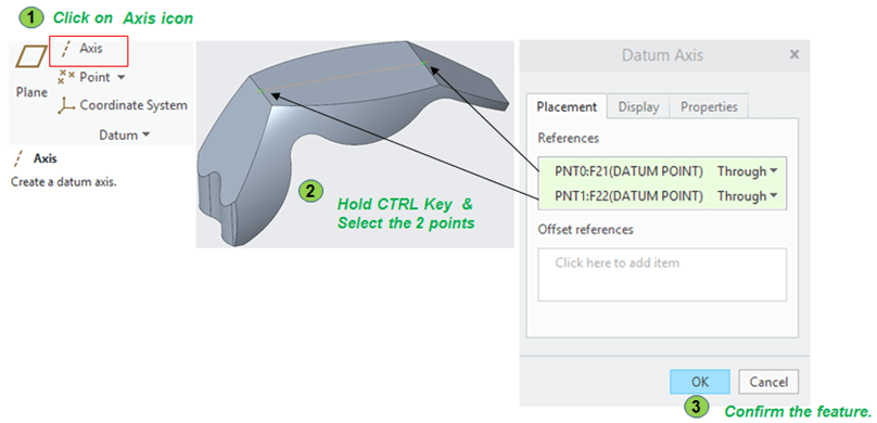
STEP 14.
Using the 2 points from the previous Step, now continue with Axis
STEP 15.
And now continue to create 2 planes. For the first one do as follows:
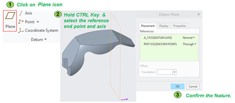
STEP 16.
Create the 2nd plane somewhere in the middle of backside. Do as follows:

In case you need later to change the shape of the backside bulge, you can always change the position of this plane, by entering a new offset value.
STEP 17.
Finally the last construction elements are 2 sketches as closed profile on the backside of the part. Do this on the upper and lower edge as follows:

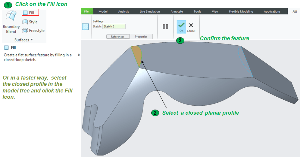
STEP 18.
Now let’s build the surfaces for the backside. At first, create 2 flat surfaces by filling the area defined by the closed sketches previously created.
STEP 19.
Create the bulge on the backside. This Step is very important. If you don’t pick or define the right points at the definition of this structure, even if you manage to create a surface, it might be very possible that everything you will add after this won’t work. Every parameter in this Step is very important to be clearly defined. So click on Style icon to enter the Style Environment and proceed with surface creation , as follows:
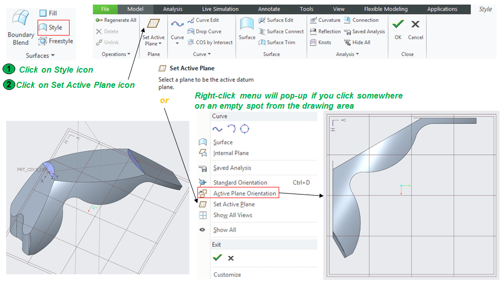
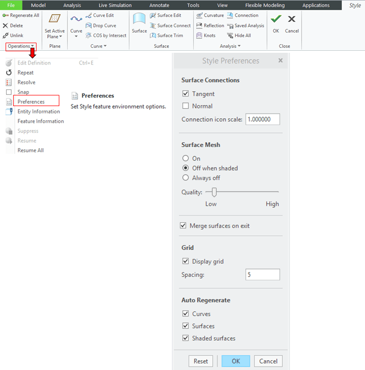
As additional information, under the Operations Group you can customize the Style preferences according to how yo want to control the design process. Click on Preferences and try the different options available.
Also very useful is the Right-click menu which pops-up when you do a right click on an empty space in the drawing area. You can create new Style features and/or control how you want to manipulate the elements during the surface design process.
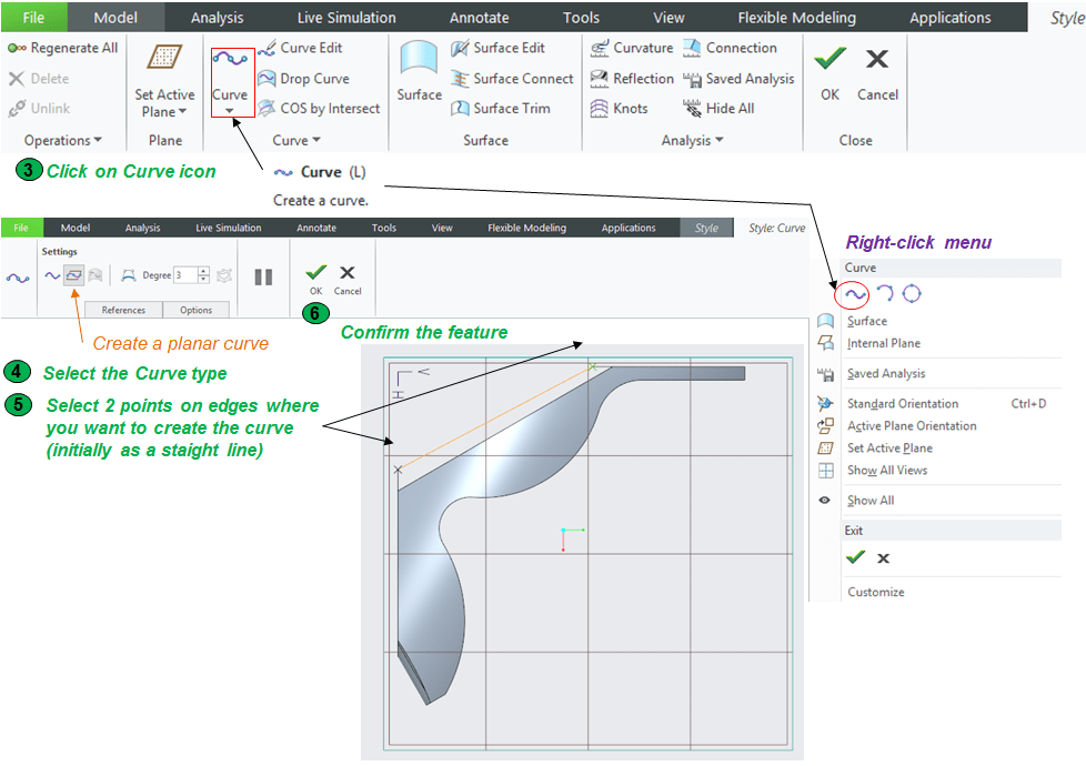
To select edges Hold SHIFT key while you are clicking on the edge, Creo will indicate when the Point was created showing you a little green cross on the edge.
Of course you can create passing through as many points you wish but for this designe work I suggeest you to define a planar curve between 2 points and edit the curve afterwards.
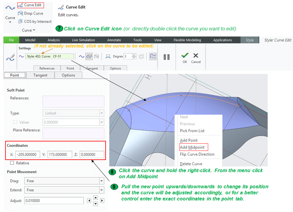
So after you’ve done and confimed the curve creation, continue to work on it and edit the reference points (one in the middle and the 2 endpoints)

STEP 20.
The curve created at the previous Step is the driving curve. Any modification you do in it it will affect all the rest added after. To have a uniform distribution of the surface in the backside of the part, a second curve is necessary which will automatically adjust anytime you change something on the driving curve. The middle point in this case is the same middle point defined for the previous curve. So the creation process is faster and easier.
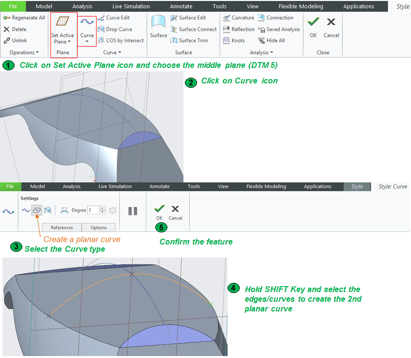
The reason why the 2 curves must be linked by the middle point is becasue the surface can be created according to these curves only if the intersect each other. This curves are considered as Internal references so if they are not connected, the surface won’t be possible.
STEP 21.
With the outer edges and the 2 internal curves, the bulge can be generated on the backside of the part. Stay on Style Environment, click the Surface icon and proceed as follows:

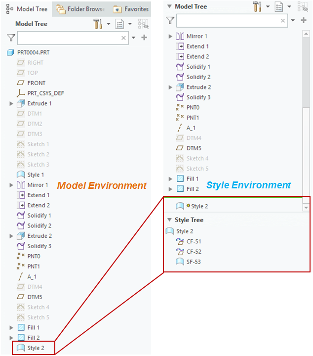
Notice that there is also a difference in the Model tree. All the Style features are only visible in Style Environment.
STEP 22.
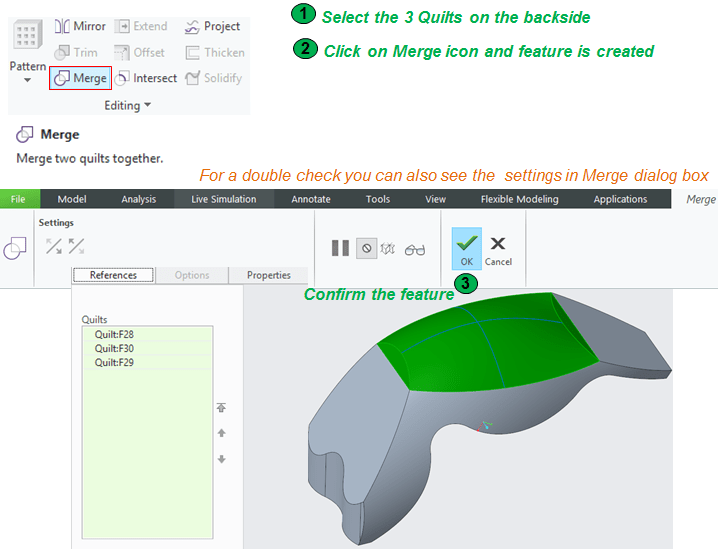
Back in Model environment, using the bulge surface you can now finalize the shape on the backside. Use the Merge feature to join all 3 surfaces on the backside.
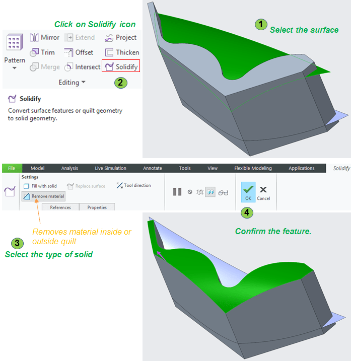
STEP 23.
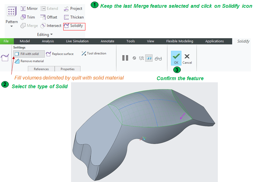
Now Solidify everything and the main shape is ready for fine-tune.
STEP 24.
With the main shape created, continue now with the final adjustmets. Create the necessary rounds as follows:
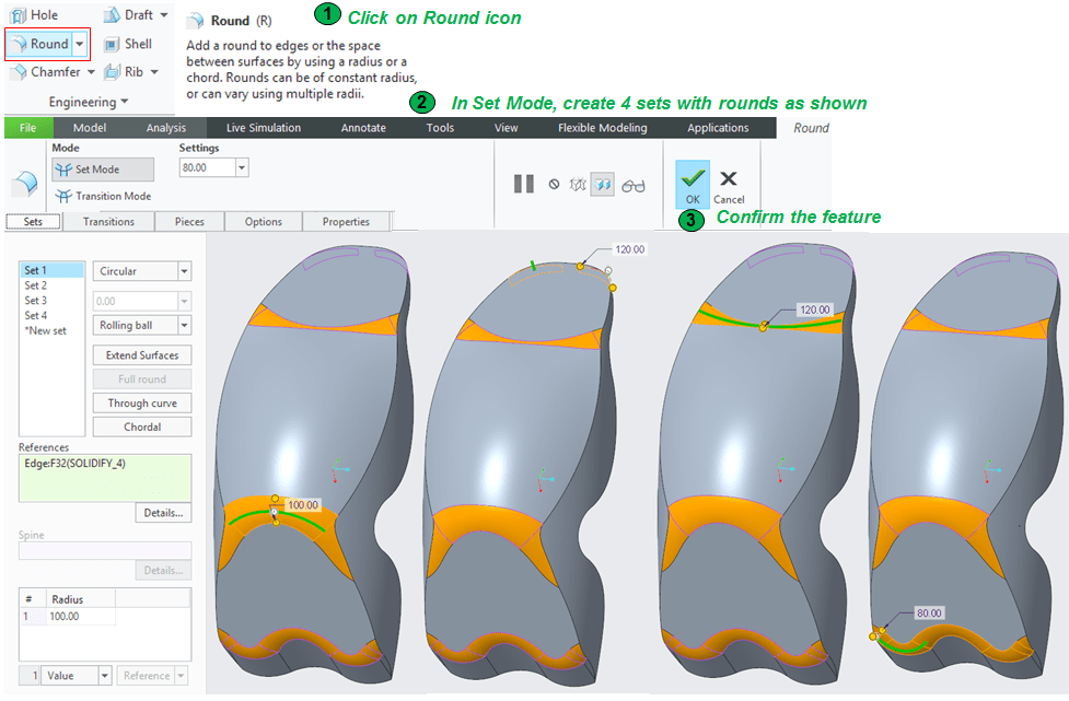
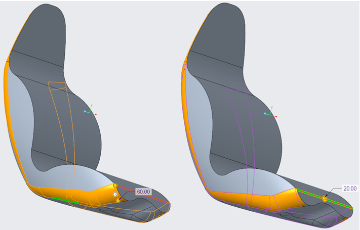
The order of adding rounds is also very important. I recommend you to start with rounds on short edges.
STEP 25.
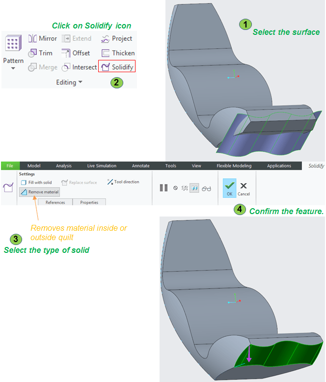
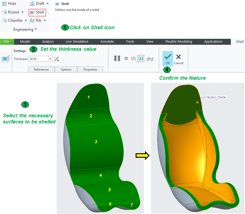
Remove the bulk from the from side by shelling the part and make it look more attractive.
STEP 26.

Add the last rounds and the part design is ready.
STEP 27.
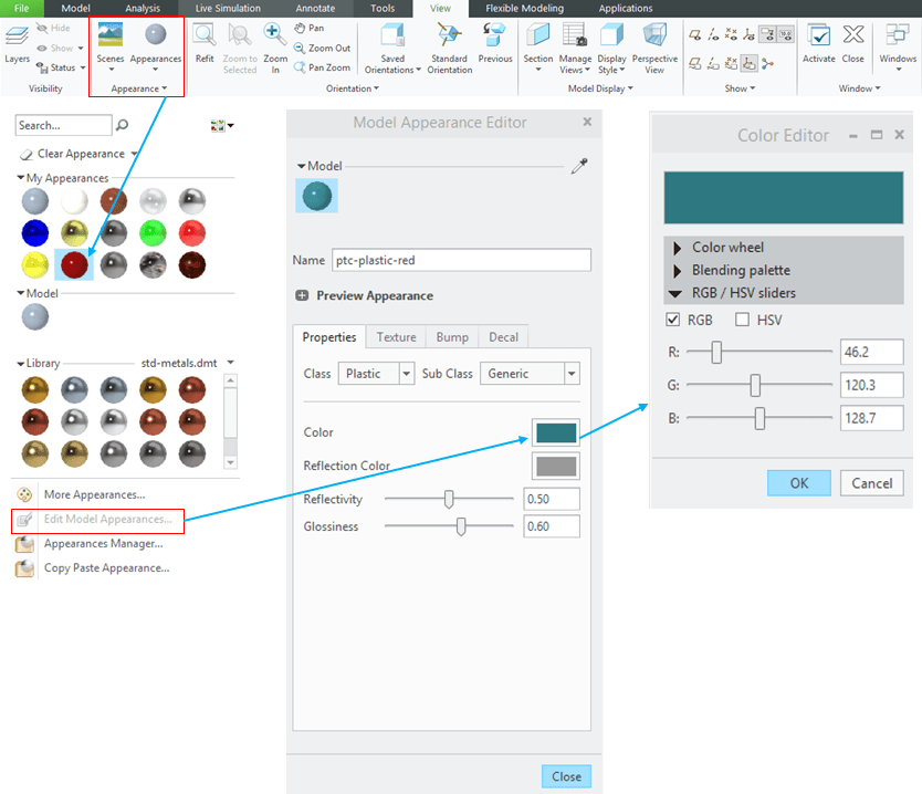
For a more aesthetic aspect now you can put a nice color on you part using the Appearances options from the View Ribbon.

The Empty seat looks like this.
Component 2 – SEAT CUSSIONS
On the main body you must add a components that makes the product more pleasant. Being a seat part, it must be confortable. So it’s a great idea to add cussions on it.
STEP 1.
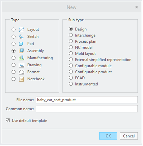
The cussions must be adjusted on the main body so is appropiate to create an assemby of them based on the Seat shape. Click on New Icon and as Type select Assembly.
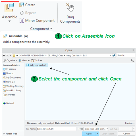
In the new assembly add the seat body as default element.
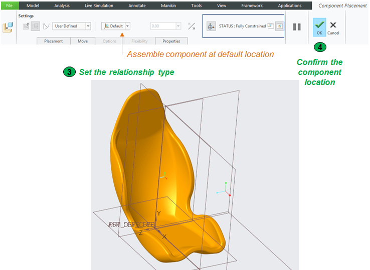
Define its possition as default location.
STEP 2.
Now in the assembly, create a new part which is exactly the cussions layout. Click in Create icon and follow the sequence as shown:
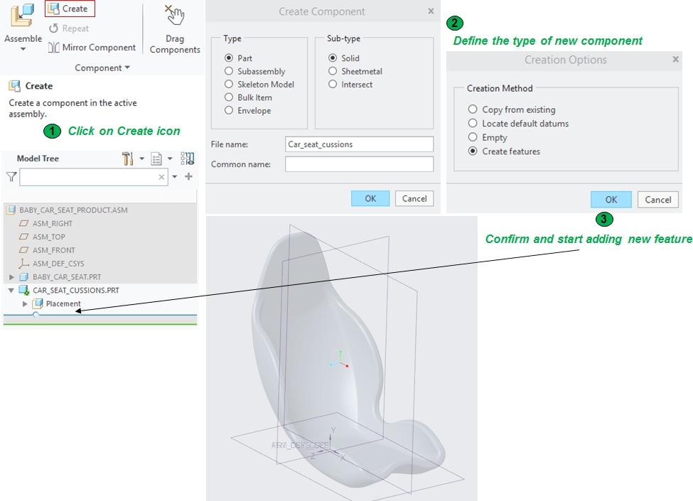
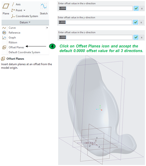
By defaut parts created directly in an assembly environment are without datum references, so you can either leave it like that or generate a default coordinate system. Personally I prefer to always have a coordinate systel available for each individual components. So in the Datum Group click in Offset Planes and follow the next sequence:
STEP 3.
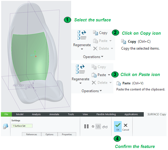
The to create cussions is very simple. You only have to copy and paste the surfaces where you want to add a cussion selecting that directly from the Main Body.
STEP 4.
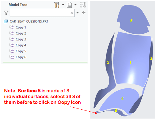
Do the STEP 3 for each necessary surface (in this case 6 times)
STEP 5.
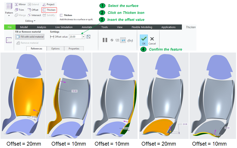
On the copied surfaces add the appropiate thicknesses as follows:
STEP 6.
The head area is a flat surface with a complex profile, so for this one do it as an extruded profile as follows:
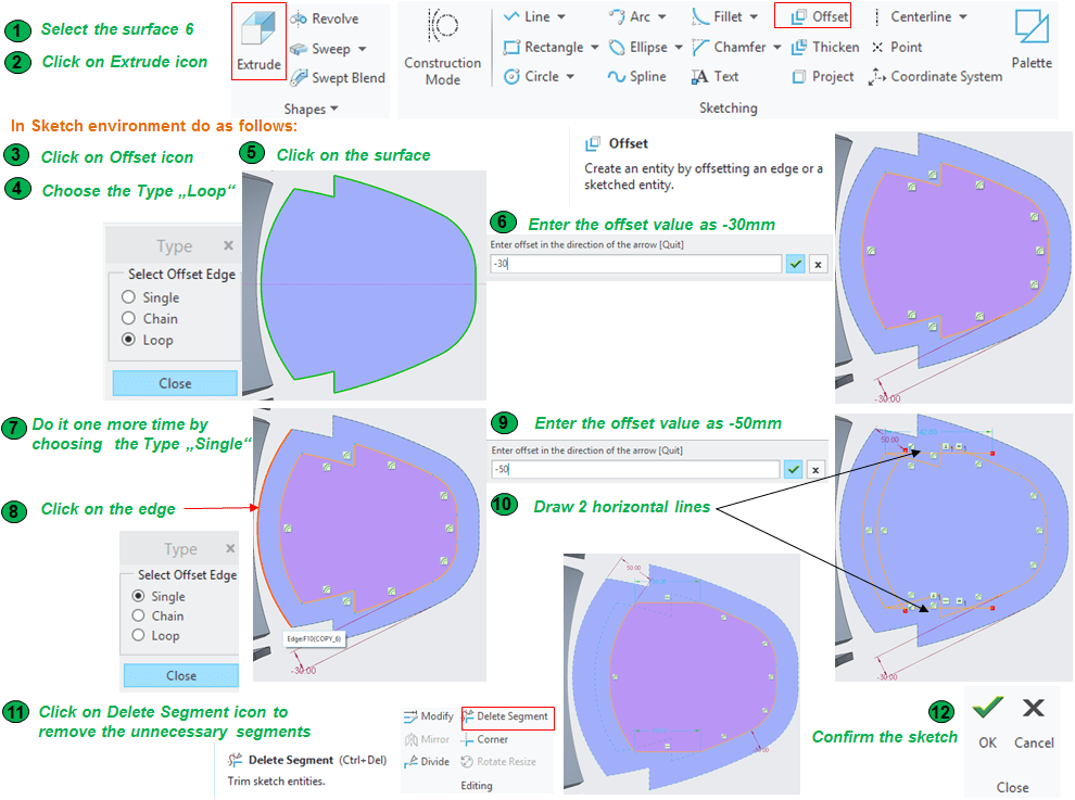

If needed you can always try new Depth values.
STEP 7.

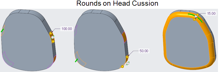
Add rounds for the final dress-up as follows:
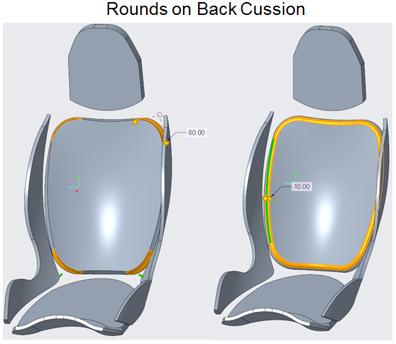
Create these rounds as 2 different features.
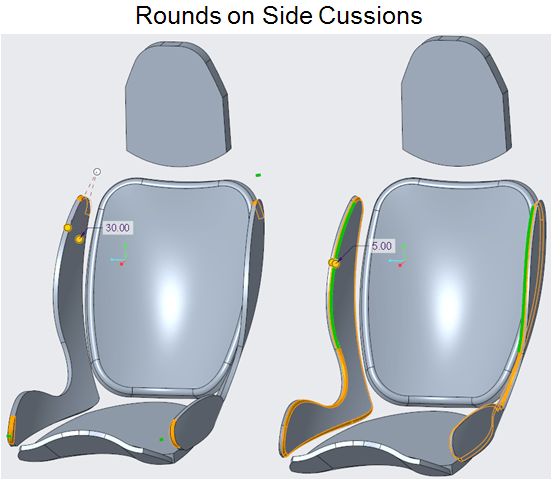
Create these rounds as 2 different features.
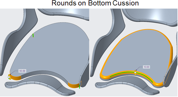
Create these rounds as 2 differnt features

Create these rounds as 2 differnt features.
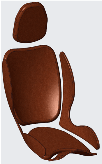
Apply the new appearance fron the View Ribbon and Cussions design is ready.
BABY CAR SEAT PRODUCT

This work is also available as video version on my YouTube Channel as embedded below:

Leave a comment