
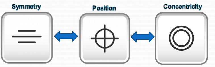
Location tolerances determine the nominal location or ideal location of a feature relative to one or more references. This results in 3 types:
- Position: the nominal location is determined by theoretical dimensions
- Coaxiality/Concentricity :The nominal location is the axis or the center of the reference element
- Symmetry: The nominal location is the median plane or line of the reference element.
Concentricity and Symmetry are special cases of Position (I´ll talk about each of them in a dedicated article). Position tolerance is closely related to dimension tolerance; it is – to put it casually – a clearly made dimensional tolerance and thus one of the most important types of tolerance in general. The most general form of location tolerances are Profile tolerances with corresponding references, mostly with a complete reference system.
Special Note: In this post I explain why it is much better to use a Position tolerance and Basic Dimensions over locating your feature with a coordinate dimension system. The two methods of using Position discussed in this article will be RFS (Regardles of Feature Size) and under a material condition (Maximum Material Condition or Least Material Condition). However, since this is such a useful symbol, it’s almost impossible to give you examples with all possible cases, so I will try to show you some of the most frequent.
Description.
True Position is actually just referred to as “Position” in the ASME Standard. Many people refer to the symbol as “True” Position, although this would be slightly incorrect. The Position tolerance is the GD&T symbol and tolerance of location. The True Position is the exact coordinate, or location defined by basic dimensions or other means that represents the nominal value. In other words, the GD&T “Position” Tolerance is how far your features location can vary from its “True Position”. This tolerance limits the position of the tolerated element relative to reference respectively (often) to a reference system. For this reason the position tolerance is related to dimensional tolerance, especially with the length tolerance. Also DIN ISO 5458 standard outlines the position tolerance possibilities with many examples.
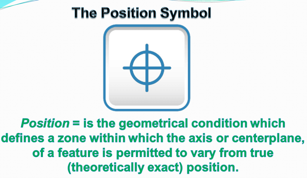
Position is defined as = the total permissible variation that a feature can have from its “true” position.
Depending on how it is called out, true position can mean several different things. It can be used with Max Material Condition (MMC), Least Material Condition (LMC), projected tolerances, and tangent planes. It may apply to any feature of size (Feature with physical dimensions like a hole, slot, boss or tab) and control the central elements of these size features.
The true/exact location of a feature of size is defined by basic dimensions which is shown in a box and are established from datum planes or axes. When a material condition modifier is specified a boundary named “virtual condition” is established. It is located at the true position and it may not be violated by the surface or surfaces of the considered feature. Its size is determined by adding or subtracting depending on whether the feature is an external or an internal feature and whether the material condition is specified.
True Position – Location of a Feature = Position in terms of the axis, point or plane defines how much variation a feature can have from a specified exact true location. The position tolerance is a 2 or 3-Dimensional tolerance zone that surrounds the true location where a feature must lie. Usually, when specifying true position, a datum is referenced with x and y coordinates that are basic dimensions (do not have tolerances). This means that you will have an exact point where the position should be and your tolerance specifies how far from this you can be. The location is most often positioned with two or three datums to exactly locate the reference position. The true position is usually called out as a diameter to represent a circular or cylindrical tolerance zone. (However, it can also be called out as a distance for X and Y coordinates as well – see final notes below).
True Position using material conditions (MMC/LMC) = Position used with Maximum Material Condition becomes a very useful control. True position with a feature of size can control the location, orientation and the size of the feature all at once. MMC true position is helpful for creating functional gauges that can be used to quickly insert into the part to see if everything is within spec. While true position on its own controls where the reference point locations need to lie, true position in MMC for a hole sets a minimum size and positional location of the hole to maintain functional control. It does this by allowing a bonus tolerance to be added to the part. As a part gets closer to the MMC, the constraints become tighter and the hole must be closer to its position. But, if the hole is a bit larger (but still in spec), it can stray from its true position further and still allow proper function (like a bolt passing though).
Symbol: –The symbol of position tolerance is interpreted as a cross thread, similar with that seen in the microscope lenses (as shown in figure 1.) This
symbol is specified in the left compartment of the feature control frame and it is used to describe the position of one referenced feature to a datum surface or line.
The Tolerance call out: For drawing call-out in case of position tolerance, as general rule at least the following 3 inputs are necessary:
- Position tolerance value tPS in mm (without prefix, meaning not ±tPS/2);
- Datum references, usually as reference systems for a clear fixation;
- Theoretical values for lengths (also for angles in degree °) to the datum reference.

A position tolerance is specified using a feature control frame displaying the “position” characteristic symbol followed by a compartment containing the positional tolerance value. (see Fig. 2). Within the compartment, the positional tolerance value may be followed by an MMC or LMC modifying symbol. Any additional modifiers, such as “statistical tolerance,” and/or “projected tolerance zone” follow that. The tolerance compartment is followed by one, two, or three separate compartments, each containing a datum reference letter. Within each compartment, each datum reference may be followed by an MMC or LMC modifying symbol, as appropriate to the type of datum feature and the design. For each individual controlled feature, a unique true position shall be established with basic dimensions relative to a specified DRF (Datum Reference Frame). True position is the nominal or ideal orientation and location of the feature and thus, the center of the virtual condition boundary or positional tolerance zone.
For this the following rule is recommended:
“If the nominal design (ideal design) is described with theoretical exact dimensions, then the associated right-angled axis and regular circular divisions are also considers as being exact.”
How Does It Work? . In the past, it was customary to control the location of a feature on a part by specifying for each direction a nominal dimension accompanied by plus and minus tolerances. In Fig. 3, the measured hole location shall be 20 ± 0.05mm from the end of the shaft. Since the hole is drawn on the center line of the shaft, we know it must be well centered. But plus or minus how much?

Let’s assume the tolerance for centrality should match that for the 20mm length. In effect, then, the axis of the hole shall lie within a 0,05 x 0.05 mm square box. Such a “square box” tolerance zone rarely represents the true functional requirements. The standards neither explain nor prohibit this method, but Y14.5 expresses a clear preference for its own brand of positional tolerance to control the orientation and location of one or more features of size, or in some cases, bounded features, relative to a DRF. A positional tolerance provides no form control.
At MMC or LMC—Where modified to MMC or LMC, the tolerance establishes a virtual condition boundary.
Remember that: the virtual condition boundary and the corresponding size limit boundary differ in size by an amount equal to the positional tolerance.
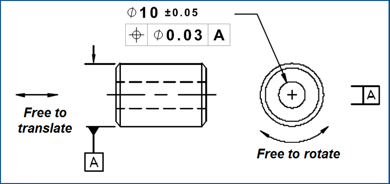
At RFS (Regardles of Feature Size)—Unmodified, the tolerance applies RFS and establishes a central tolerance zone within which the feature’s center point, axis, or center plane shall be contained.
Alternative “Center Method” for MMC or LMC—Where the positional tolerance applies to a feature of size at MMC or LMC, the alternative “center method” may be applied as described next:
The tolerance zone is uniformly enlarged by bonus tolerance—a unit value to be added to the specified geometric tolerance.
At MMC = Bonus tolerance equals the arithmetic difference between the feature’s actual mating size and its specified MMC size limit. Actual mating size is the dimensional value of the actual mating envelope, and represents the worst-case mating potential for a feature of size. Thus, actual mating size is the most suitable measure of actual size in clearance-fit applications or for most features having a boundary of perfect form at MMC.
For instance, a hole having an actual mating size Ø 0.02mm larger than its MMC, a Ø 0.02 of bonus tolerance is added to the specified geometric tolerance.
At LMC = Bonus tolerance equals the arithmetic difference between the feature’s actual minimum material size and its specified LMC size limit. Actual minimum material size is the dimension of the actual minimum material envelope. Actual minimum material envelope is defined according to the type of feature, as follows:
- (a) For an External Feature = is a similar perfect feature counterpart of largest size, which can be inscribed within the feature so that it just contacts the surface(s).
- (b) For an Internal Feature = is a similar perfect feature counterpart of smallest size, which can be circumscribed about the feature so that it just contacts the surface(s).
In certain cases, the orientation, or the orientation and location of an actual minimum material envelope shall be restrained to one or two datums.
For any feature of size, including cylindrical, spherical, and width-type features, a virtual condition boundary and/or derived center element is easily defined, and positional tolerancing is readily applicable.
FAQ: Can positional tolerancing be applied to a radius?
A: No. Neither virtual condition boundaries nor central tolerance zones can be used to control the orientation or location of a radius or a spherical radius. There are no definitions for MMC, LMC, axis, or center point for these non-size features.
Tolerated element: the position tolerance is used either for real planes and lines and for derived elements such as axis (often) and centerplanes, lines or points.
The basic dimensions may be shown graphically on the drawing, or expressed in table form either on the drawing or in a document referenced by the drawing. Figs. 4 and 5 show five different methods for establishing true positions.

I – Base line dimensioning – For each of the two Ø 2.5 holes shown in Fig. 4, a basic dimension originates from each plane of the DRF. Manufacturers prefer this method because it directly provides them the coordinates for each true position relative to the datum origin. CMM inspection is simplified, using a single 0,0 origin for both holes.
II – Chain dimensioning – In Fig. 4, a basic dimension of 20mm locates the upper Ø4 hole directly from the center plane. However, the lower Ø4 hole is located with a 40mm basic dimension from the true position of the upper hole. People often confuse the 40mm basic as originating from the actual axis of the upper hole, rather than from its true position. A manufacturer needing the coordinate of the lower hole will have to calculate it: 20mm – 40mm = -20mm Or is it -20mm?
III – Implied symmetry dimensioning – In many cases, the applicable basic dimensions are implied by drawing views. In Fig. 4, the true positions of the two Ø6 holes have a single 30mm basic dimension between them, but no dimension that relates either hole to the planes of the DRF. Since the holes appear symmetrical about the center plane of the DRF, that symmetrical basic relationship is implied.
IV – Implied zero-basic dimensions – The view implies the relationship of the Ø8 hole to the planes of the DRF as represented by the view’s center lines. Obviously, the hole’s basic orientation is 0° and its basic offset from center is 0. These implied zero-basic values need not be explicated.
V – Polar coordinate dimensioning – Rather than by “rectangular coordinates” corresponding to two perpendicular axes of the DRF, the true positions of the eight Ø10 holes shown in Fig. 5-(a) are defined by polar coordinates for angle and diameter. The Ø90 “bolt circle” is basically centered at the intersection of the datum planes, and the two 45° basic angles originate from a plane of the DRF. Figs. 5-(b) and (c) show alternative approaches that yield equivalent results, based on various methods and fundamental rules I’ve presented.
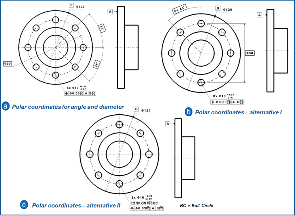
All the above methods are acceptable. Often, a designer can choose between base line and chain dimensioning. While both methods yield identical results, I prefer base line dimensioning even if the designer has to make some computations to express all the dimensions originating from the datum origin. Doing so once will preclude countless error-prone calculations down the road.
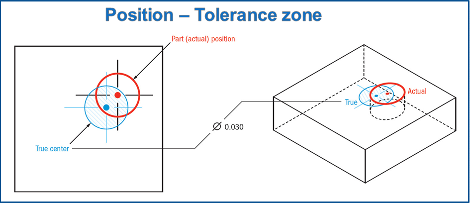
Tolerance zone
True Position –Location of a feature = A 2-dimensional cylindrical zone or, more commonly a 3-Dimensional cylinder, centered at the true position location referenced by the datums.
The cylindrical tolerance zone would extend though the thickness of the part if this is a hole. For the 3-dimensional tolerance zone existing in a hole, the entire hole’s axis would need to be located within this cylinder.
True Position using modifiers (MMC/LMC) = The tolerance zone is the same as above except only applied in a 3D condition. A 3-Dimensional cylinder, centered at the true position location referenced by the datum surfaces. The cylindrical tolerance zone would extend though the thickness of the part if this is a through hole for the 3-dimensional tolerance zone similar to the RFS version. While this is the tolerance zone, the call-out now references the virtual condition of the entire part. This means that the hole’s position and size are controlled together as one. (see gauging section)
When is the Position tolerance used?
Position tolerances is used to locate features of size from datum planes such as a hole or keyway and used to locate features coaxial to a datum axis.
Datums for Positional Control – One of the chief advantages of a GD&T positional tolerance over plus and minus coordinate tolerances is its relationship to a specific DRF. Every positional tolerance shall reference one, two, or three datum features. The DRF need not restrain all 6 degrees of freedom, only those necessary to establish a unique orientation and location for true position. For example, the DRF established in Fig. 7 restrains only 4 degrees of freedom. The remaining 2 degrees, rotation about and translation along the datum axis, have no bearing on the controlled feature’s true position. Thus, further datum references are meaningless and confusing.
A datum feature of size can be referenced RFS (the default where no modifier symbol appears), at MMC, or at LMC. When MMC or LMC is selected, the DRF is not fixed to the part with a unique orientation and location. Instead, the DRF can achieve a variety of orientations and/or locations relative to the datum feature(s).
Examples of use
In the following examples, I will use holes, since these are the most common types of features controlled by true position. Yet Position tolerance can be used on any feature of size (but not on surfaces where we would use Profile tolerances).
True Position –Location of a feature – In example 1 you can see how a hole can be called out using true position. However, this can also be applied to anything in need of a location tolerance, such as a pin, a boss or even an edge of a part. When you have a hole in a part such as a bolted surface, true position is usually called out. It can be used almost anywhere to represent any feature of size.
True Position using material condition (MMC/LMC) – True position of a feature of size under MMC is used when a functional gauge is ideal for checking the part. True position is also useful for describing and controlling a bolt pattern for a pipe fitting or a bolted fixture. If you specify the control using MMC, it allows you to have a pin gauge that you can insert into the part to see if the bolt pattern is functionally accurate. You will see true position called with MMC very commonly in bolt patterns where relative location of all the bolts and necessary clearance is critical. LMC with true position is a little less common but often used when minimum wall thickness is desired.
Example 1 – True Position –Location of Hole
Four holes are to be located on a block to ensure contact is always maintained and located within a specific position. The holes need to line up with the threaded connections in the mating part.

With true position called out the holes do not need to be in exact positions as shown in Fig 8 on the measurement area, but their centers can vary by the amount specified by the tolerance. The basic dimensions (dimensions in the squares) are un-toleranced and describe the true location the hole would be in if it was perfect. In a 2D check of the upper right hole, the true location would be 40 mm from datum A and 40 mm from datum B. The holes center is calculated, usually by a CMM and compared to the true location. As long as the holes center is in the blue tolerance zone of 0.2 mm specified by the feature control frame, the part is in tolerance.
Note: in this case, the surface of the part is called out (Datum C). This means the entire hole must have its axis align with the datum. The tolerance zone would actually ensure that the location and the perpendicularity are within the specified tolerance. Since all the central points at any cross-section are controlled by true position, the parts axis (line between all central points) would be controlled for orientation.
The biggest thing to note about this design is that no matter what size hole you have, your true position would always have to be the same. This is ideal for when proper exact alignment is required for function of the part. It does, however, remove the possibility of using a functional gauge.
Example 2 – True Position – Hole size and location using MMC
Taking the same design example as the previous one, the true position can also be specified with a Maximum Material Condition callout. This means you are now controlling the envelope of the entire hole feature, including the size of the hole throughout its entire depth. With an MMC callout you now can use a functional gauge to measure this part, to determine that the size and geometric tolerancing are within spec at the same time.

Formula for a the functional gauge to measure the true position of all holes:
- Individual Pin Diameters = Min hole Ø -True position tolerance (bonus)
- This example Pin Ø = 9.9 – 0.2 = Ø 9.7
- Location of pins: Same specifications
This would be the go gauge that would measure for hole size, orientation, and position. The part would be pressed down onto the gauge and if it fits the part is in specification. Notice that datum A, B, and C are all included in the gauge to check the location of the hole. The desired function of the part is met by ensuring that the part touches all the datums and that the gauge pins are able to fully go through the holes. As long as the gauge can go into the part, it is in spec. This makes it very easy to accurately gauge the part right on a production line. The function of the part is confirmed because as long as the surface that the part is bolted to has the same tolerances, it will always fit.
EXAMPLE 3 – Dependence between the position and dimension tolerance
In fig 10- a , the dimension 30 ±0.1 mm between holes and edge is a distance value (where admittedly it can not have any Maximum Material limit dimension). In practice this kind of dimensional tolerance – previously more common alone – is seen as clearer and simpler. But this is basically a mistake.
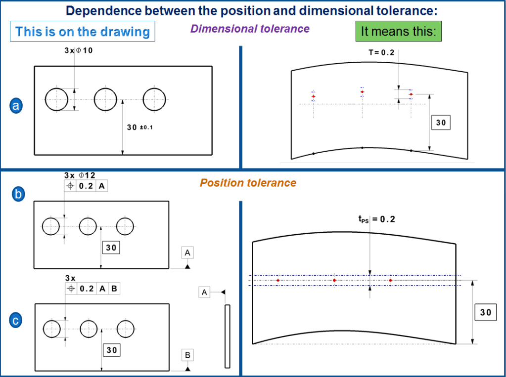
A dimension is the distance between 2 points in opposite positions; in our example the dimension entry as distance from the hole axis is be measured from the edge.
If the edge is crooked as shown in fig 10-a on the “means this” area, then the hole pattern must be also curved – a somehow a strange notion if we think about an assembly. This often requires a straight hole pattern and dimensions related to the adjacent component – and this is exactly what the position tolerance offers as shown in Fig. 10 b (“on the drawing” and “means this” area). For a thin sheetmetal besides the main datum surface a second reference datum is necessary. (fig 10-c). This kind of approach is old but the drawing representation is unusual. It converts the dimensional tolerance in explicit inputs.
Note: the holes in the fig 10 are only measured in perpendicular direction; the additional necessary dimensioning and tolerancing in the horizontal direction are omitted. However a dimension entry with initial reference, can not replace the reference system.
EXAMPLE 4 – Dependence between the position tolerance and dimensional deviations
In fig 11-a a single hole is defined with the dimensional tolerance of 30±0.1 mm similar with Fig 10 a (on the drawing). When the Nominal dimension is 30.15 as shown in “means this” for fig 11-a, the hole is lying out of tolerance. This results from the comparison between the nominal N = 30.15mm versus the prescribed tolerance limits (max. 30.1mm and min 29.9mm), or likewise from comparison between the nominal (+0.15mm) and tolerance limits (±0.1mm). Here, nobody would consider by default the idea to compare the Nominal (+0.15mm) with the dimensional tolerance T= 0.2mm. This is exactly equally senseless for the case of defined Position tolerance from fig. 10-b (on the drawing) to compare the position deviation (+0.15mm) with the Position tolerance tPS = 0.2mm (Fig 10-b “means this”). The tPS may only be compared with the limit deviation tPS/2=±0.1mm. The “problem” resulting from this is that the dimension is always within the tolerance limit (0.2mm) and not in the Nominal position (±0.1).

NOTE: The simplified entry of the lower surface as primary datum A in fig. 2-45-c and the other examples shown here, corresponds to ISO 5459. It indicates the reference point as a small open circle and the hidden part of the reference line is dashed. It can save an eventually additional drawing view.
EXAMPLE 5 – Cylindrical Tolerance zone.
The position of the hole in fig. 12-a-1 is tolerated in 2 directions related to a fully defined reference system. For the fixation in the vertical direction (dimension 25) the tertiary datum reference C is not necessary. However here the datum C is entered to make sure that both position tolerances are verified in the same setting. The additional tolerance zone is quadratic Fig 12-a-2. It permits a position deviation of 0.1mm in both directions yet in the diagonal direction is just one deviation of around 0.14mm permited. Oftentimes in terms of functionality it makes sense to allow this tolerance value (0.1mm) around all directions, for example in case of a circular bolt should pass through a hole.

This is possible for the position tolerance with a cylindrical (tubular) tolerance zone of Ø28mm (as shown in fig. 12-b –1 and b-2) having the following characteristics:
- The drawing will be simplified because only one tolerance is entered (instead of 2 like shown in fig 12-a-1)
- at the same limit deviation (0.14mm) the cylindrical tolerance zone is 57% bigger than the quadratic one with the same diagonal (fig 12-a-2), meaning that the manufacturing will be more reliable and cheaper.
- a mechanical measurement (with a dial gauge or other similar instruments) will be expensive because the measurement must be done all around, but however with a measurement equipment this won´t play any role in term of costs.
- a checking with insertion gauges (with Maximum Material Condition) corresponds mainly with a cylindrical tolerance zone.
From these reasons the cylindrical tolerance zone is often prescribed. Yet for a dimensional tolerance such cylindrical tolerance zone is not possible. When the limit deviation is prescribed, there is nothing else left than to define the tolerance zone (approximatively) quadratic, like that being often tightly related to its corresponding functionality.
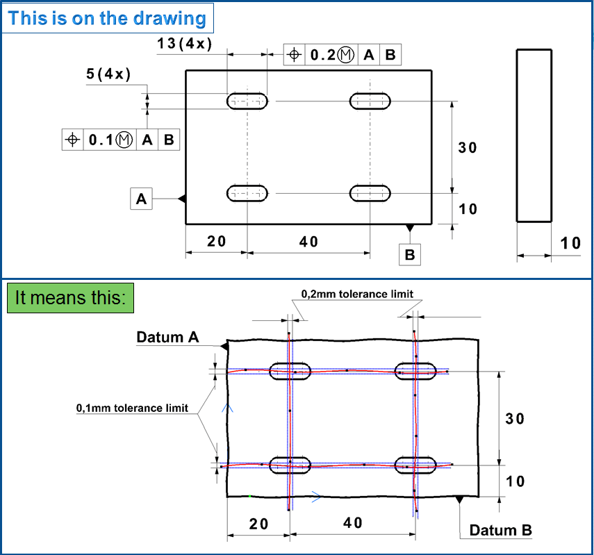
EXAMPLE 6 – Tolerance of a hole patterns.
Often is necessary to tolerate more than one hole in a specific order, holes which must pass through a counterpart and to create a hole pattern. In this case the same position tolerance is used multiple times. Fig 13 a-1. In case of doubt it can be noticed on the tolerance frame which holes belong to that pattern (for example 6x Ø12 H9). The holes in fig 13- a-1 have a fully defined reference system just like those in fig 12.

The fig. 13 a-2 sketches 3 datum references entered exactly perpendicular on each other, all being connected to the outer side of the workpiece and the 4 cylindrical-shaped tolerance zones of Ø0.3mm must lie within their 4 hole axis.
EXAMPLE 7 – Floating hole patterns
It can happen that the holes from a pattern may have quite big position tolerances, but they must be much more precisely below each other (meaning relative to one another) so that the counterpart fits in with a multiple connector or with a press table that is guided by 4 columns. Then the pattern is defined with theoretical dimensions (fig 14 a-1) and carries a position tolerance with inputs of the corresponding holes leaving the datum references out, a so called “Floating tolerance”.

The 4 cylindrical-shaped tolerance zones lie on the 4 edges of an ideal rectangle of 20mm x 30mm (as shown in Fig. 14 a-2), this being itself movable, rotatable and tiltable. The 4 axis must be somehow accommodated within (for verification).
But often makes no sense to allow the tolerance zones of the “floating” holes to be tilted. In this case all 4 could stay crooked with the same tilt as shown in fig. 14 a-2. Then the counterpart will indeed fit in, but it will remain sloped. When the tolerances are calculated – often unaware – is it assumed that the tolerance zone stays perpendicular to the main input surface. In order to reach that, the main input surface (in this example surface A) is entered as reference datum (as shown in fig. 13-a-2) but the other references are omitted. The hole pattern may now still move and rotate but it cannot tilt.
The Floating Position tolerances for hole patterns require the following characteristics:
- corresponding holes Labeling on the patern
- position tolerance for holes
- theoretical distance between the holes
- no datum reference except in general the primary datum on the main input surface
In all rules the hole patern must be additionally fixed to the workpiece edges, however with bigger tolerances. Then is recommended that the Position tolerances from Fig 13 (entirely) to Fig 14 b-1, to be entered together (as shown in fig. 15-a). For the edge related Tolerance is not advisable to use dimensional tolerance. Both tolerance types (geometric and dimensional) often don´t fit together because they are measured differently (fig. 12) and it would be absurd to use the ambiguous dimensional tolerance when the position tolerance for the floating hole pattern is already used. (A floating position tolerance is hardly representable with dimensional tolerance).
EXAMPLE 8 – Floating hole pattern with internal reference.
Instead of a floating hole patern as shown in fig. 14 b-1 it can be also convenient to define a hole (or 2) as reference in the patern , for example in order to check the other holes from this reference hole by means of inside micrometer. In fig. 15-b, the placement for the 3 small holes is related to the big hole D. Here it should be mounted a centering collar with 3 flange bolts. In turn the main input surface A serves a primary reference. Besides that all holes are defined with bigger tolerances related to the edges B and C, of course also with the primary reference on the surface A . These 2 entries are checked independently from one another.

Hole pattern measurement.
Hole patterns can be approached with a dial gauges and testing pins. Therefore the cylindrical tolerance zone is less favorable than quadratic one. However floating hole patterns are hardly measurable with quadratic zones. Most of the time it´s preferred to measure that with a Coodinate Measuring Maschine. For hole patterns, these CMM instruments scan the hole walls, then create a nominal axis and try to fit this in the tolerance zone (as shown in fig. 13 a-2 and fig 14 a-2 & b-2)
In case of a floating tolerance the measuring instrument tries to rotate and move the scanned tolerance zone (fig. 14 a-2) in such a way that the 4 nominal axis fit in. However depending of the instrument age the measurement can be also done mechanically. The checking gauge for the floating hole pattern has 4 testing pins, which instantaneously check the mating capability of the hole pattern with the help of the counterpart, however with a constraint: each hole has its own diameter tolerace.
The checking gauge just fit when the holes have completely exhausted their minimum diameter, meaning the Maximum Material condition and position tolerance. If only one hole is a little bit bigger in its dimensional tolerance frame, then the position and limit deviations can exceed and the gauge can still fit in. The prescribed tolerance is exceeded but the hole is however functional. This measurement is therefore functional, auditable and practical it only doesn´t exactly check what´s on the drawing. This consideration leads immediately to Maximum Material Condition which this type of measurement also contains it.
Other examples of use.
Up to now the subject was only about holes. The position tolerance can be also used for many other geometrical elements. In fig.16 I show you some of such examples:
- Position tolerance of real edge elements (a): the left side edge of each of the 3 cutouts of an optical pinhole is tolerated on 0,02mm relative to the reference edge as datum B with primary reference A. Each edge can be moved, sloped or crooked or have any other combined deviation.
- Position tolerance of an inclined surface (b): in fig. 2-48-b besides the orientation as angularity tolerance at 75° for the front face the position tolerance is also specified.
- Position tolerance of the center of a sphere (c): The DIN EN ISO 1101:2006 contains also a position tolerace with spherical-shaped tolerance zone. Like that central point of a sphere is constrained on all sides. In this case the tolerance zone has the spherical symbol as “SØ” entered in the tolerance frame.

Oblong holes Pattern
This is similar with the case shown at Example 6, the difference being that the holes are not circular but oblongs. The position of these hole must lie in 2 different tolerance limits as 0,2mm on vertical direction and 0,1mm on horisontal direction.
Gauging/ Measurement.
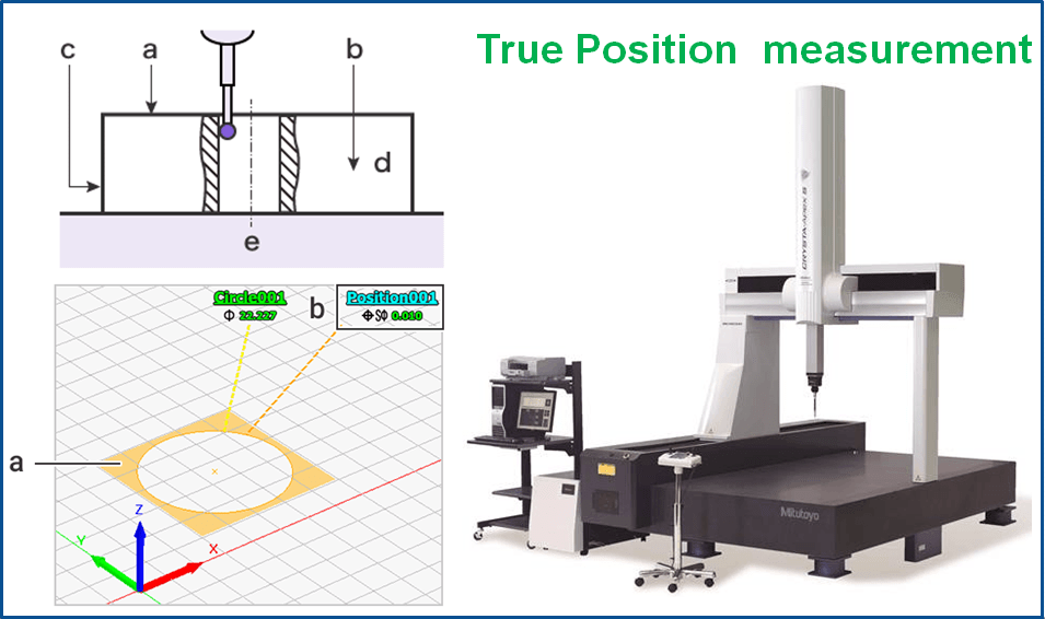
True Position – Location of a feature = True position of a feature is made by first determining the current referenced point and then comparing that to any datum surfaces to determine how far off this true center the feature is. It is simplified like a dimensional tolerance but can be applied to a diameter tolerance zone instead of simple X-Y coordinates. This is done on a CMM or other measurement devices.

True Position Using material modifiers (MMC only): When a part is checked for true position under a feature of size specification, usually a functional gauge is used to ensure that the entire feature envelope is within specification. If you have a specification for Maximum Material Condition, the desired state is that a hole will not be too small, or a pin not too large. The following formulas are used to create a gauge for true position under MMC.

Locations of the gauge pins or holes are given on the drawing as basic dimensions. All gauge features should be located in the datum true positions, but sized according to the formulas above.
NOTE on Bonus Tolerance: When a functional gauge is used for True Position, any difference the actual feature size is from the maximum material condition would be a bonus tolerance. The bonus tolerance for position then increases as the part gets closer to LMC. The goal of a maximum material condition callout is to ensure that when the part is in its worst tolerances, the True Position and size of the hole/pin will always assemble together. For instance, if you had a large hole size but was still in tolerance (closer to LMC), you make more bonus tolerance for yourself making the true position tolerance larger. You can now have the hole center more out of position due to the bonus tolerance.
Bonus Tolerance = Difference between MMC & Actual condition.
Relation to other GD & T Symbols
True Position – Location of a feature
True position is closely related to symmetry and concentricity as they both require the location of features to be controlled. However, True position is more versatile since it can be called on a feature of size or combined with other geometric tolerances to specify an entire part envelope.
True Position using feature of size (MMC/LMC)

True position with used of MMC or LMC is related to axis perpendicularity when used on a hole or pin. The tolerance of both perpendicularity and true position now refers to the uniformity and cylindrical envelope of a central axis. However, with true position you can make the tolerance referenced to several datum’s as opposed to just one with axis perpendicularity. When you callout true position using datums on the face, and sides of the part – perpendicularity is controlled as well. See example 2 for more details.
Final Notes
Bonus Round : Remember the further you are from MMC when it is referenced in the feature control frame, the more bonus tolerance you are allowed. For a hole, the larger the diameter, (closer to the LMC) the more bonus tolerance you have for your true position.
Bonus tolerance = true position tolerance (measured hole size – MMC hole size)
NOTE: Keep in mind the opposite is true for a positive feature like a pin, where the smaller the pin means you have more bonus tolerance.
Called with or without the Ø symbol: There are two ways true position can be called out – either as a distance, in X and Y or most commonly as a diameter. When true position is called out as a distance, you are permitted to move from the tolerance in X or Y direction by the allowed tolerance. However, when done this way, the tolerance zone actually forms a square. This is usually undesirable since in the corners of the square are further from the center than the sides. This also removed over 57% of your tolerance zone! Most commonly, true position with reference to location is called with the diameter (Ø) symbol to be called as a cylindrical or circular tolerance zone.
Slotted Features: Another common way true position can be called out is with slotted features. If you have a slot in your part that must always be located correctly, you can use true position to ensure that each of the planes that make up the slot are always located in the correct position. Symmetry can also be used in this case – but only if the slots have a referenced datum plane that they are symmetrical about (and measuring symmetry is very difficult!).

Figure 12 example 5 appears to be wrong. Maybe the views were swapped?
LikeLike
Yes, You are right, thank you so much, I didn’t notice but indeed by mistake I swapped the views, I’ve just updated it. If you notice other errors like this on my GD&T articles please let me know.
Or if you have any other suggestion with practical examples based on your experience, I am glad to share my knowledge with this blog but in the same time I am always curious to learn for others. Your comment is valuable for me , so many thanks once again for reading my blog, I appreciate you for this. 😉
LikeLike