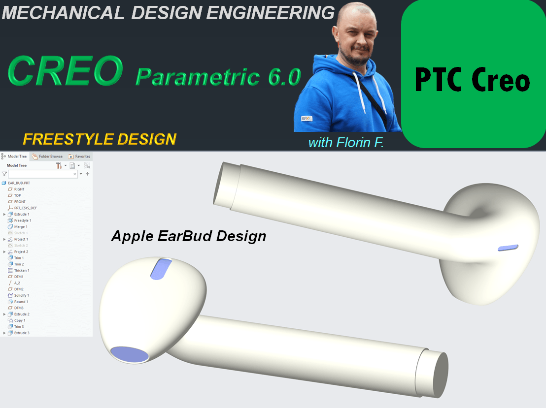
There are many objects which are commercially succesful if their design make them look attractive. Such example of products are those made by Apple. They use a lot of Freestyle design and one example here is the already well known Wireless Earbud. In this post I am showing you how this product can be designed using the Freestyle design environment from CREO Parametric CAD software.
So, let’s start.
STEP 1.
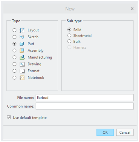
Create New Part.
STEP 2.
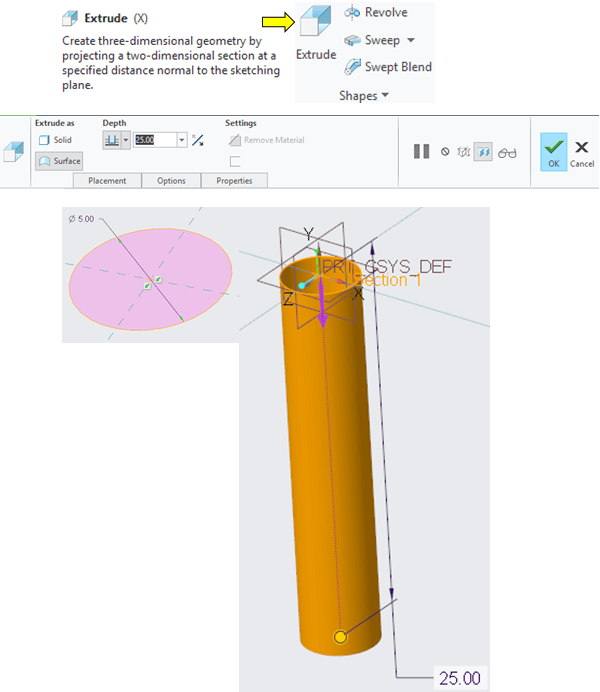
On TOP datum plane create the 1st feature as an extruded cylindrical surface, of diameter = 5mm and 25mm length.
STEP 3.
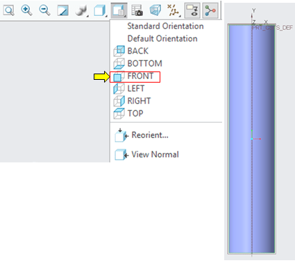
Orient the view on the FRONT view.
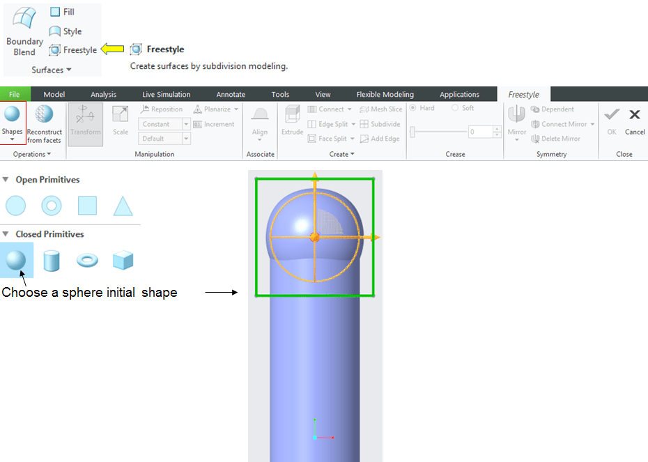
Most of the work is done in the Freestyle work environment as basic functionality of Creo. To open that, in the Surfaces group in the Model Workbench, click on Freestyle icon and Creo will enter into the Freestyle environment. To start the work you must pick one of the Primitive Shapes in this case a Sphere, which you will start pushing and pulling it around adding bits on rolling it out. So by clicking the Sphere icon a Sphere is places right up of the top of the coordinate system within Creo. By default the Sphere has a mesh around it on which you can start picking and clicking, pushing and pulling, rotating, adding bits on using sort of extrudes and that sort of stuff.
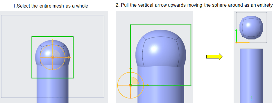
Using the Freestyle design you will generate the main shape of the Earbud. The first move is to do a big box selection to select the entire mesh as a whole and start moving that sphere around as an entirety.
STEP 4.
Keep the entire mesh selected and under the Right-hand mouse button a very useful menu of tools is available hepling you to control the freestyle design.
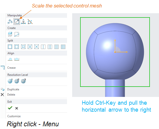
Under this menu select the Scale icon and pull the horizontal arrow to the right increasing the size of the sphere as shown.
STEP 5.

Rotate the view on the RIGHT side and deselect by clicking the background.
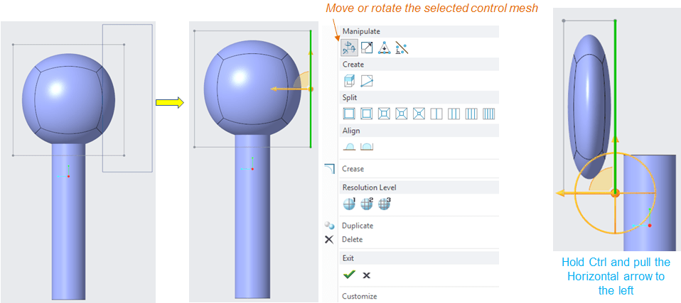
Then drag a box section on the right hand edge and from the right-click menu convert the movement into a translation by clicking the “Move or Rotate” icon, hold the CTRL key and pull the horizontal arrow to the left as shown below creating the approximative front face of the Earbud.
STEP 6.
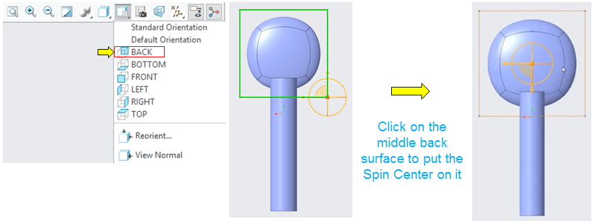
Change again the orientation view on the BACK side and click on the Back surface.
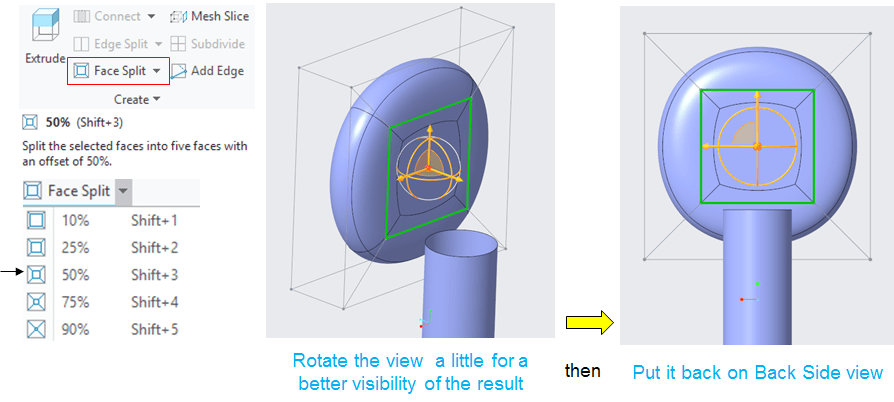
This back surface must be subdivided meaning that a smaller face will replace the exisitng one. Hence, in the create group click on the “Face Split” icon and from its expanded menu choose how small my new face should be. In this case choose 50%.
STEP 7.
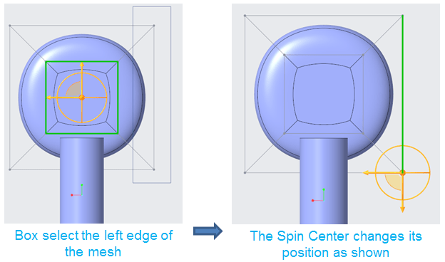
Box select the right hand edge…
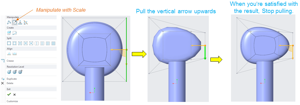
… and from the right-click menu click on “Scale” icon and pull the vertical arrow upwards without holding CTRL key.
STEP 8.
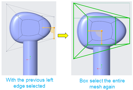
Box select the entire mesh again.
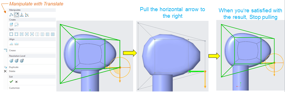
From the right-click menu click on “Translate” icon and pull the horizontal arrow to the left until the result looks like shown below:
STEP 9.
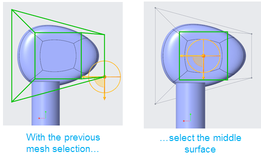
Click on the middle surface…
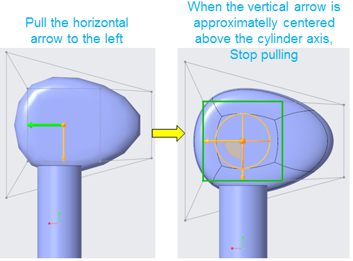
… and do the same operation, translating just the middle face a little bit to the left.
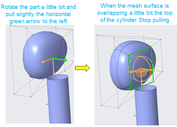
Keep the middle face selected and also pull it a little bit outward.
STEP 10.
Orient the view on the RIGHT side, and continue the adjustment.

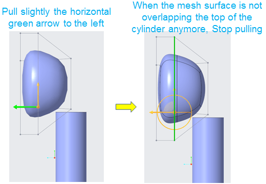
Continue the translation until the result is satisfactory.
STEP 11.
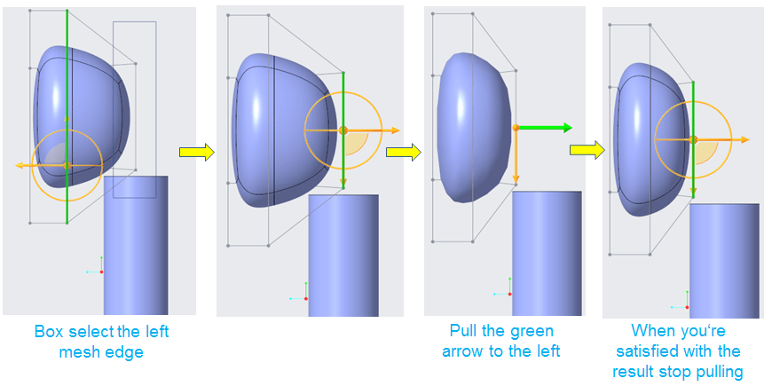
Do the same with the right hand edge until you have the result you want.
STEP 12.

Rotate a little bit the geometry and from the Right-click menu, click in Extrude icon.
STEP 13.
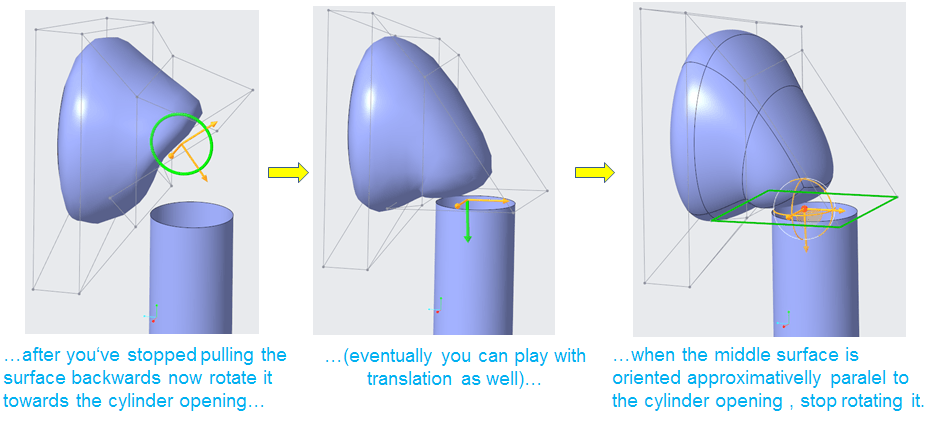
The middle surface gets an extruded lump. By dragging the green arrow backwards, continue to addjust the shape as shown:
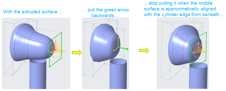
When you’re done with the translation, rotate the middle surface towards the cylinder opening.
STEP 14.
The next thing to do is to orient the middle surface so that the freestyle geometry can be connected with the cylinder beneath.
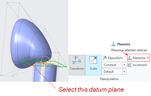
In the Manipulation group, click on Planarize icon and select the TOP datum plane, and the surface will be alligned accordingly.
STEP 15.
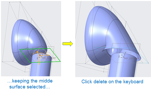
At this stage, The middle surface is no longer needed, so keeping it selected and just click on DELETE key to remove it completelly.
STEP 16.
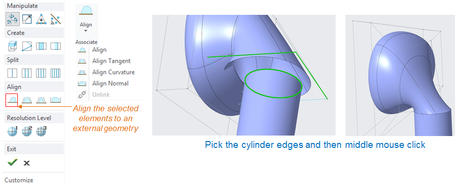
Now the Freestyle geometry has an opening which must be alligned with the parametric geometry (the cylinder)

To do the allignment click on the front edge of the mesh and with SHIFT key pressed pick the sidewise edge as well.
With the 2 selected mesh edges, in the right-click menu pick the 1st “Align” icon and then I pick the parametric edges to which you want to align with and do a middle mouse click to finish the alignment.
As you can see the result is just a free alignment without tangency.
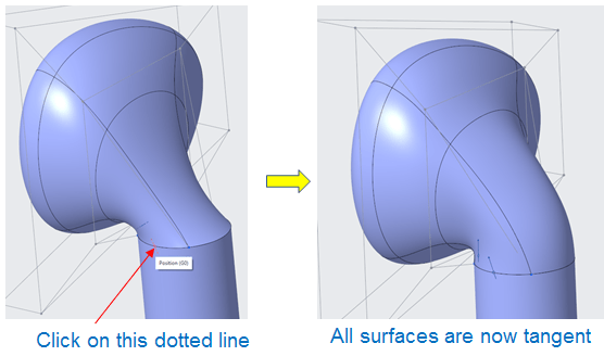
To create a surface with continuity in tangency, click on the small dotted line visible on the edge where the 2 surfaces are aligned.
STEP 17.
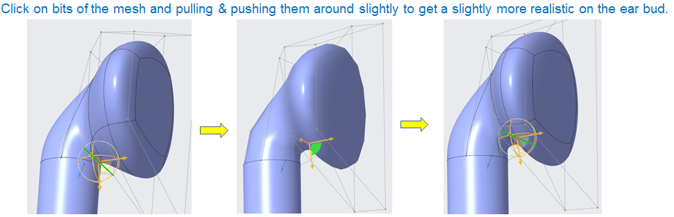
Now all the surfaces are tangent to each other. The only thing to do from here is to start tweaking the final surface by pulling and pushing the bits of mesh until the result looks realistic.
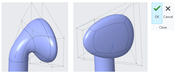
So far the freestyle surface looks good and by clicking OK the freestyle surface work is completed. Creo retuns to the parametric environment.
STEP 18.
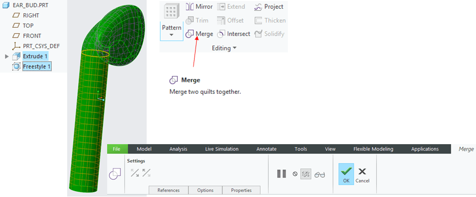
From this stage you can continue adding parametric features until the Earbud design is completed. As you can see now the design work contains 2 separate Quilts (surfaces).

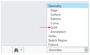
So before to continue with the next feature, change the selection filter to Quilt.
And by selecting the selecting both surfaces (by holding CTRL key either from the Model Tree or directly on the graphic view), in the Editing group click on Merge icon to generate a join from the 2.
STEP 19.

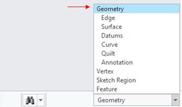
Put the selection filter back to Geometry.
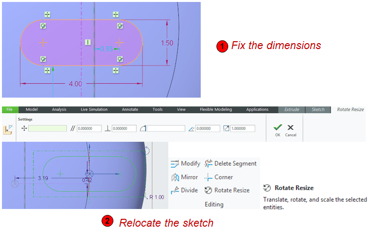
…and continue to create the necessary trims for the final design. The first one is a small cut on the front face. To do this first create a sketch on the FRONT datum plane and in the sketch environment click on the Palette icon. In the Shapes tab pick the Racetrack profile and pull it somewhere on the sketching area.

Then fix the profile dimensions. When this is done, box select the entire sketch and relocate the sketch in its final poition.
STEP 20.
Now with the new sketch selected, in the Editing group, click on Project icon and select the 2 front surfaces where you want the sketch to be projected.
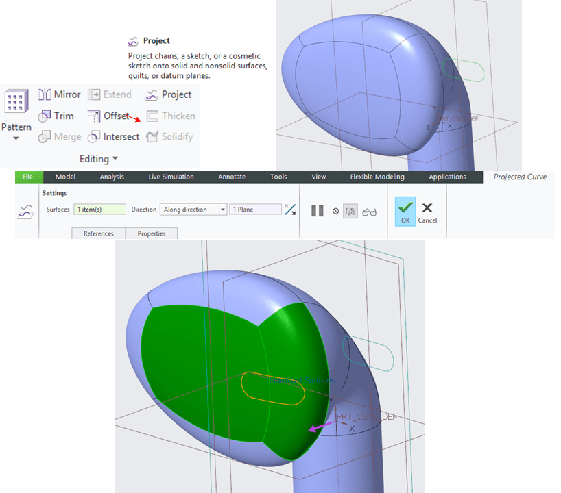
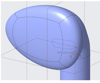
The result with the projected sktech looks like as shown here.
STEP 21.
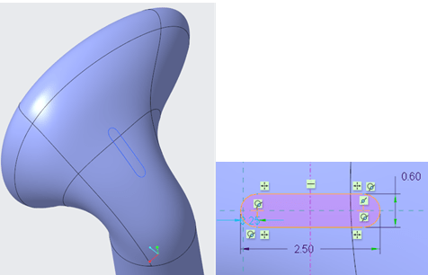
Repeat the same procedure from previous step (20) for the second trim profile.
STEP 22.
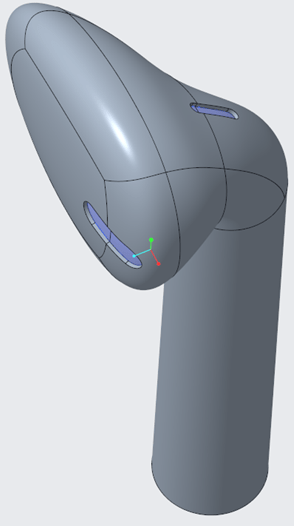
The entire geometry can now be trimmed with the 2 projected profiles.
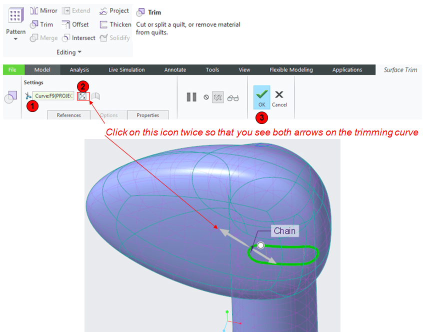
Change again the filter selection to Quilt.
…then select the Quilt and from Editing group click in Trim icon, pick the projection profile from the front side. Click twice on trimming direction arrow then click OK to finish the trim.
STEP 23.
For the backside, do the same like described at Step 22.
STEP 24.
Change the selection filter back to Geometry.
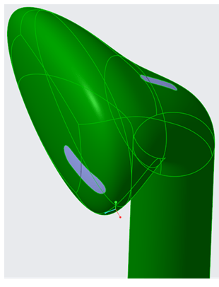
Select a surface from the main quilt, for instance the front surface and then in the Editing group click on “Thicken” icon, put 0.2 as offset value, keep the thicken directon outwards and click OK.
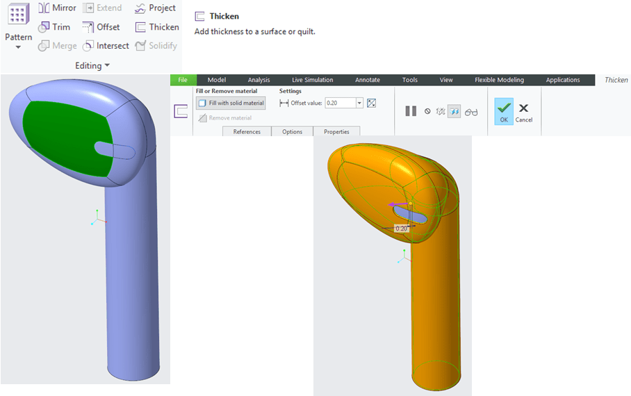
The Part with thinkness looks like this.
STEP 25.
Next is to cut the front side of the Earbud so that it will leave ourselves with an opening in this area.
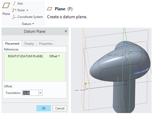
Create a new datum plane for instance with an offset of 10mm from the original RIGHT hand datum plane.
STEP 26.
For a better cut you need another plane oriented with an angle to the one you have just offseted.
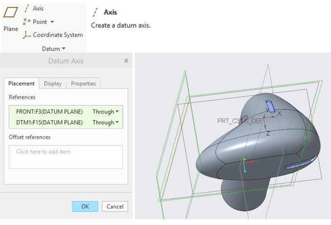
Click on the plane icon and on the Fly create a new axis defined by the offsetted plane and original FRONT datum plane.
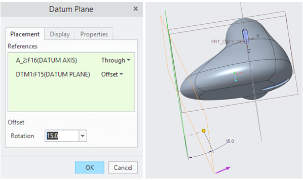
Select the just created datum axis and the DTM1 plane and set the rotation at 15° angle.
STEP 27.
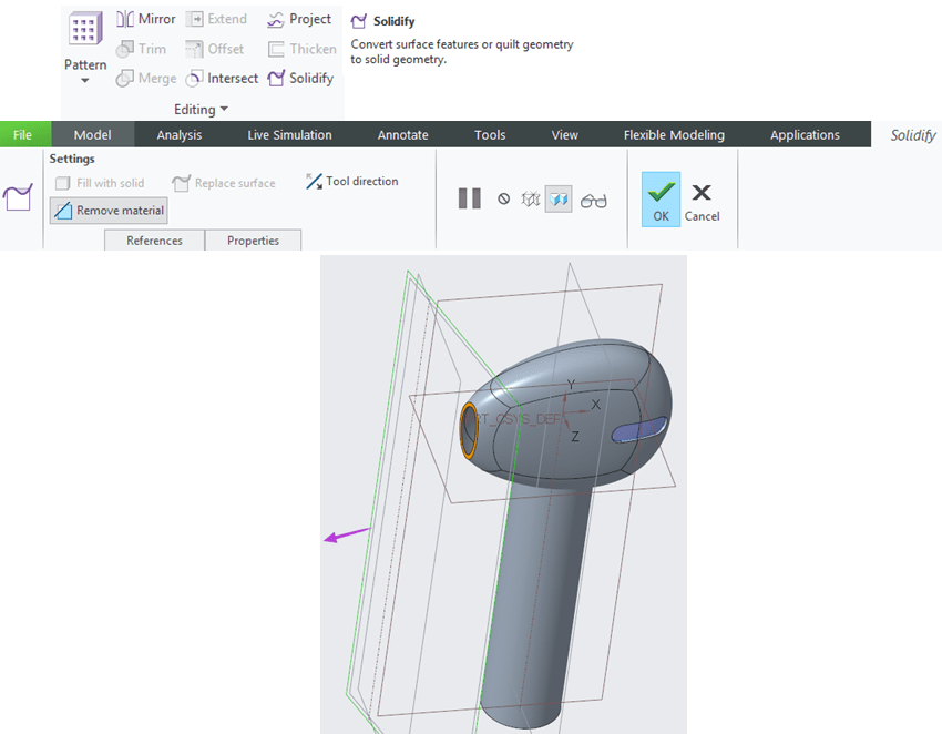
Select the DTM2 plane just created and from Editing Group click on th Solidify icon. If necessary change the cut dirrection on the good side and click OK. If the cut is too big, just modify the offset value of the DTM1.
STEP 28.
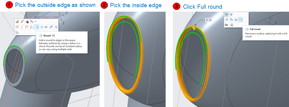
As a finish touch, the Earbud design must have a round on the front opening. To do this, click first on the outside edge and from mini toolbar pick the Round icon, then hold CTRL key, select the inside edge and again from the mini toolbar this time pick the Full Round icon , and Middle mouse click to give OK to that feature. Like this the entire front edge opening is fully rounded.
STEP 29.
The front opening must be also filled with a surface the same like for the other two previously done at Step 22 and 23 . So to create this, you need first some construction elements.
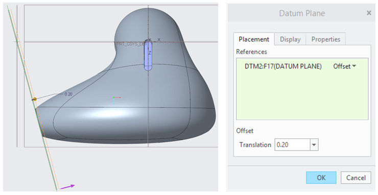
Create a new plane with an offset of 0.2mm from the DTM 2
STEP 30.
From the TOP datum plane create a new Extrude feature as surface. Draw the surface so that it coverts the entire opening.
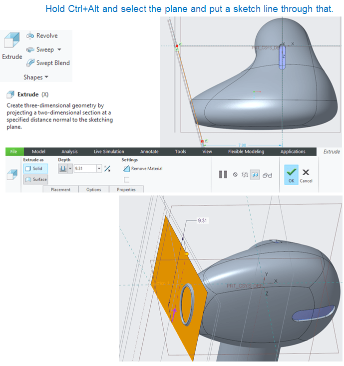
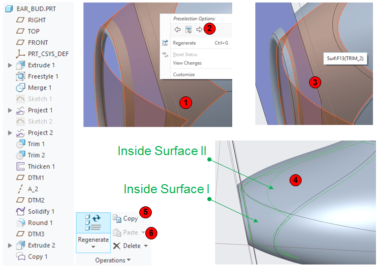
STEP 31.
The surface created at the previous Step must be trimmed by the inside surface. So to do that, first the inside surface must be extracted. This is done as follows: While hovering the Outside Surface I, right click and select the arrow poinitng to the right in the Preselection Options. The inside surface in now visible, click on it to select it. Just for precautions in case one surface is not doing the complete cut, hold CTRL KEY and select the 2nd inside surface in the same way. Them in Operations group click on “Copy” icon then again on “Paste” icon to create a feature Copy1 in the Model Tree.
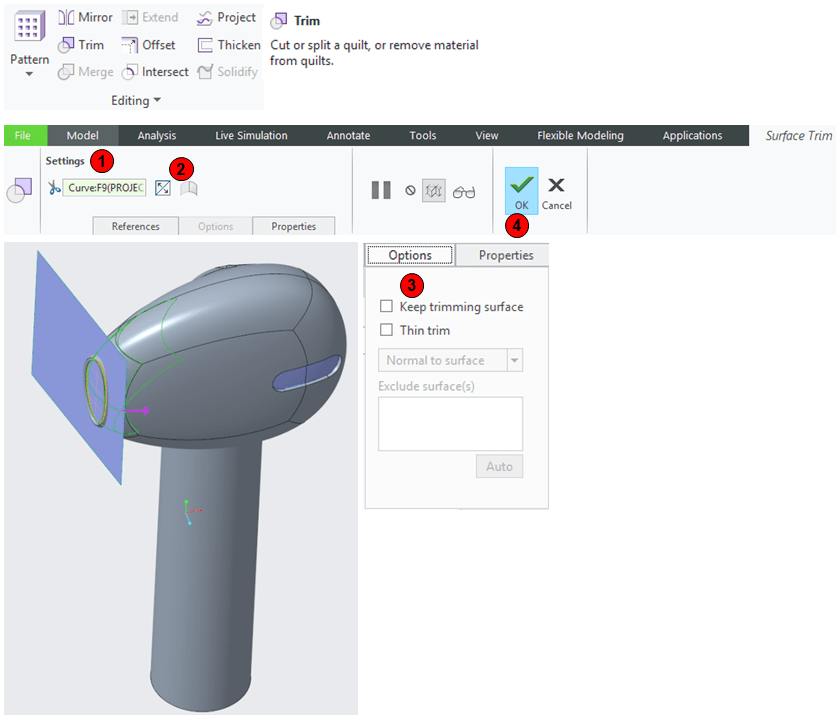
STEP 32.
With the Copied surface create a Trim of the Extruded surface from Step 30, reverse the trim direction if necessary and unselect the “Keep rimming surface” from Options tab. Then click OK.
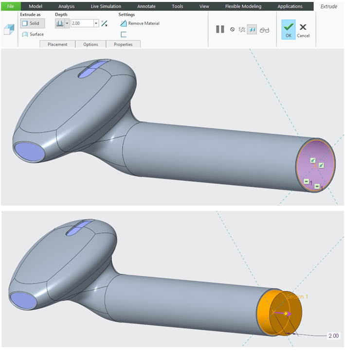
STEP 33.
The last parametric feature is a small cap as an extrude of 2mm at the bottom of the Earbud.
STEP 34.
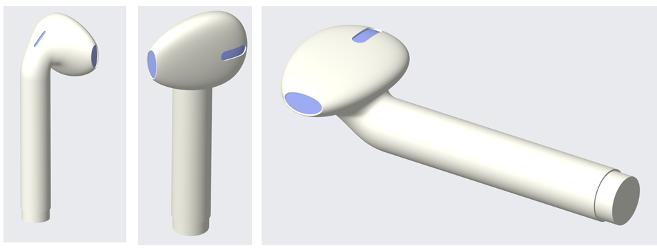
You can give your part a good looking appearace with a specific color, in this case the Apple WHITE and the EARBUD design is complete.
This exercise is also available as video version on my YouTube Channel as shown below:

Leave a comment