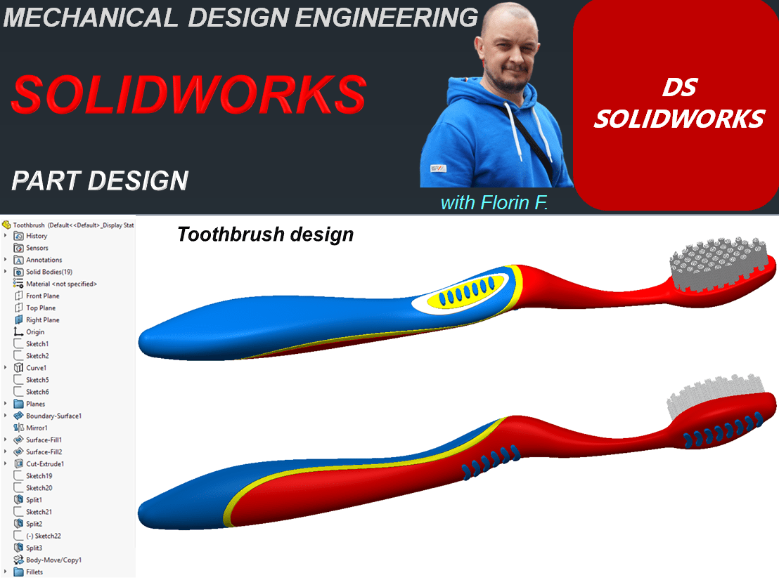
Let´s design a toothbrush with SOLIDWORKS
STEP 1.
Create a New Part.

Save the part with a new name as: Toothbrush and while you advance with the design work from time to time, don´t forget to click the Save icon.

STEP 2.
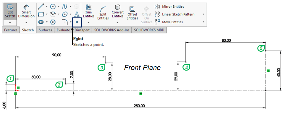
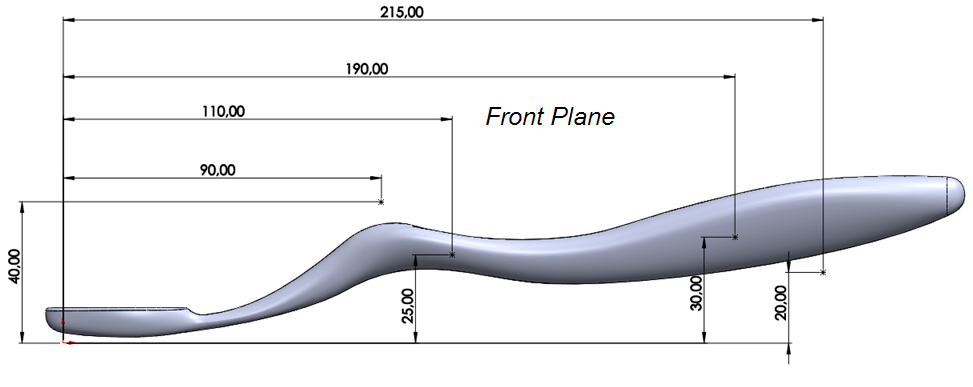
In the drawing view or from the model tree select the Front Plane and draw the reference points as shown:
STEP 3.
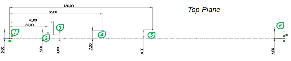
Similarly do it again with points on Top Plane.
STEP 4.
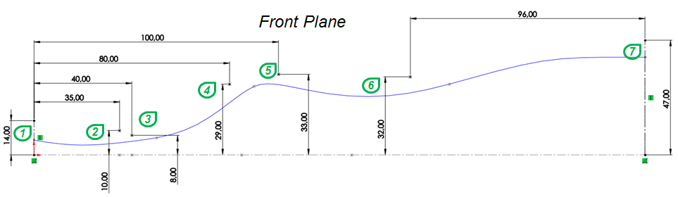
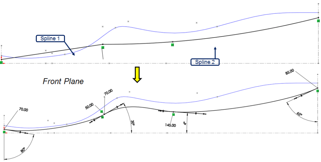
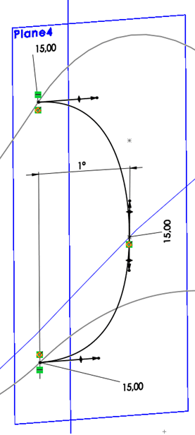
Once you have defined the drawing points, now add a profiles using the sketch elements such as Spline and Arc. Start by clicking again in the Front Plane and draw a new sketch made of 2 Splines connected through the defined points. Define the dimensional constraints and make the Splines tangent to each other as shown:

STEP 5.
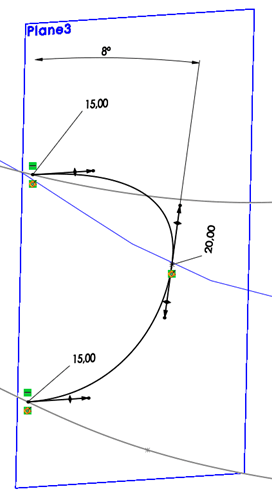
On Top Plane, create a new sketch made of 3 Splines and 1 Arc. Define the dimensional constrains and make everything continuous in tangency as shown:

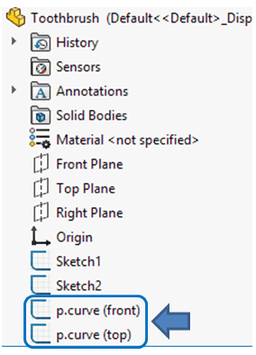
The last 2 sketches created so far are the references for all the rest that follows after them, so for clarity purpose, I suggest you to rename these 2. Just click on their name in model tree and type a name easy to remember.
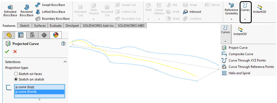
STEP 6.
Now from the combination between the 2 reference curves, the 3rd one can be generated by clicking the Project Curve icon and select the ref. curves as shown:
STEP 7.
Create a new sketch made of points on Front Plane, all points must be above the reference curve, as shown:
STEP 8.
Create another sketch made of points on Front plane, all points must be under the reference curve, as shown:

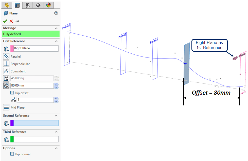
STEP 9.
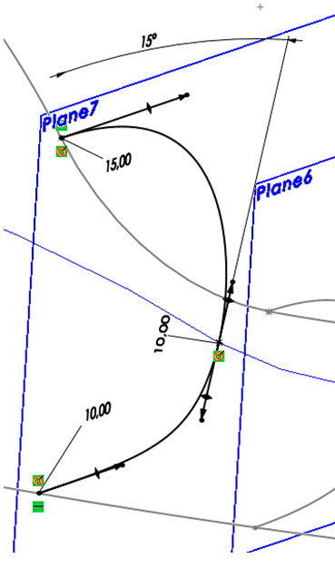
Because a toothbrush is an object with irregular surfaces, before to create its body you need to create some reference planes. For this model including the Right Plane there will be 8 planes used as reference for cross-sections. Therefore, start creating the 1st ref. Plane parallel to Right Plane through the end point of the reference curve as shown:

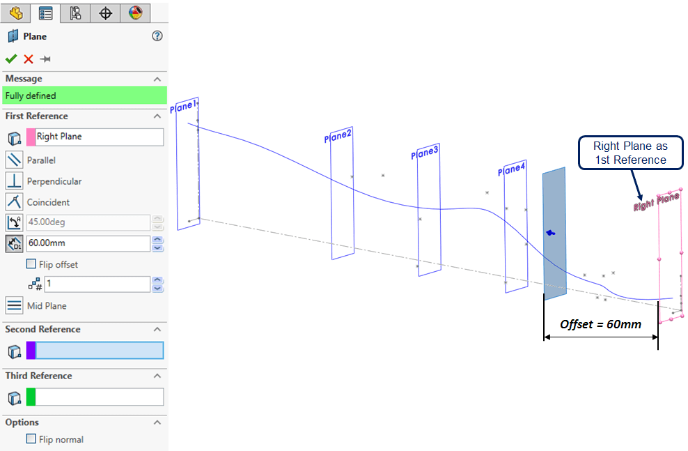
STEP 10.
Create the 2nd ref. Plane as shown:

STEP 11.
Create the 3rd ref. Plane

STEP 12.
Create the 4th ref. Plane
STEP 13.
Create the 5th ref. Plane
STEP 14.
Create the 6th ref. Plane

STEP 15.
Create the 7th ref. Plane
STEP 16.
Based on the last 2 sketches made of points, create 2 new sketches using these points as reference. On Front Plane, create a sketch made of 2 Splines continuous in tangency as a profile UNDER the ref. curve as shown:
STEP 17.
Create a sketch made of 3 Splines and 2 Arcs, put the dimensional constraints and make everything continuous in tangency as shown:

STEP 18.
Using the 8 ref.Planes defined above, you can now create the cross-sections as sketches made of a single spline connected with the 3 ref. curves.
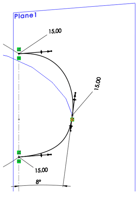
On Plane 1 , create the 1st cross-section in a sketch using a spline constrained as shown.
STEP 19.
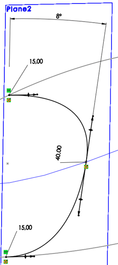
On Plane 2 , create the 2nd cross-section in a sketch using a spline constrained as shown.
STEP 20.
On Plane 3 , create the 3rd cross-section in a sketch using a spline constrained as shown.
STEP 21.
On Plane 4 , create the 4th cross-section in a sketch using a spline constrained as shown.
STEP 22.

On Plane 5 , create the 5th cross-section in a sketch using a spline constrained as shown.
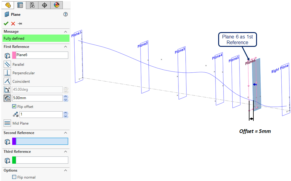
STEP 23.

On Plane 6 , create the 6th cross-section in a sketch using a spline constrained as shown.
STEP 24.
On Plane 7, create the 7th cross-section in a sketch using a spline constrained as shown.
STEP 25.
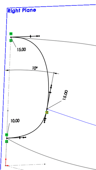
On Right Plane, create the 8th cross-section in a sketch using a spline constrained as shown.
STEP 26.
Using the 3 ref. curves and the 8 cross-sections defined above, you can now create the 1st half-surface of the toothbrush. In Surface tab, click on Boundary Surface icon and follow the settings as shown:
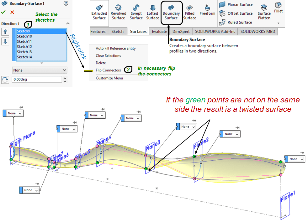
STEP 27.
For more structure in the model tree I suggest you to put all 7 additionally created ref. Planes in one folder.

STEP 28.
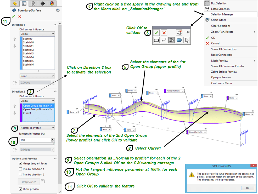
On Features tab, click the Mirror icon, select the Front Plane as Mirror plane and select the half-surface created previously and generate the 2nd half-surface, as shown:

STEP 29.
On Front Plane , create a sketch made of 2 points , one for each EndCap as shown:

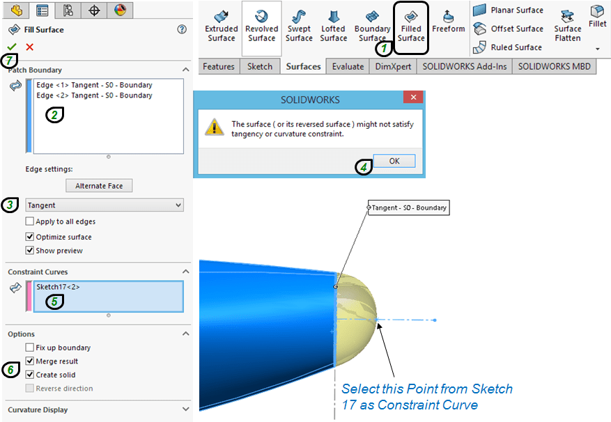
STEP 30.
In Surfaces tab, click on the Filled Surface Icon, select the edges, make them tangent with the boundary and use the point from the previous sketch to fully constrain the new surface as shown:
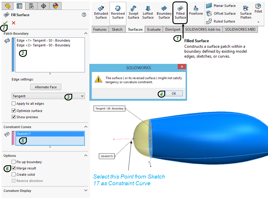
STEP 31.
Repeat the previous step for the other side, but in this case also activate the options (6) as shown:
STEP 32.

On Front plane create a sketch made of 1 line as shown:
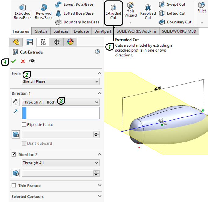
STEP 33.
In Features tab, click on Extruded Cut and use the previous sketch to cut the body as shown:
STEP 34.
On Front Plane, create a sketch made of 4 points as shown:
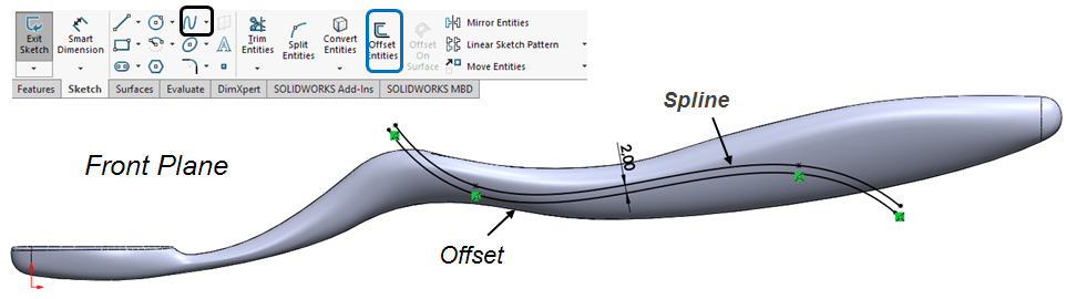
STEP 35.
Create anther sketch on front plane and draw a spline through the points from the previous sketch. Also click on Offset Entities icon and offset the spline 2mm downwards.
STEP 36.
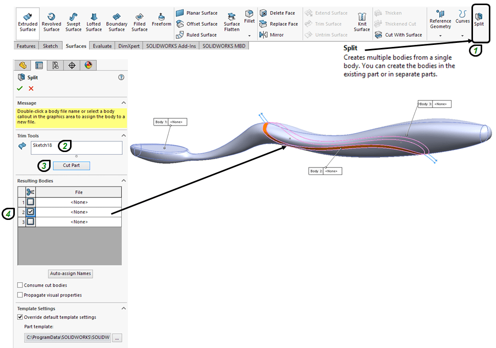
In Surfaces tab, click on Split icon, chooses the previous sketch as Trim tool and cut the part without consuming the bodies as shown:
STEP 37.
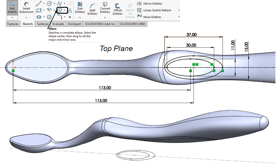
On Top Plane create a sketch made of 2 ellipses as shown:
STEP 38.
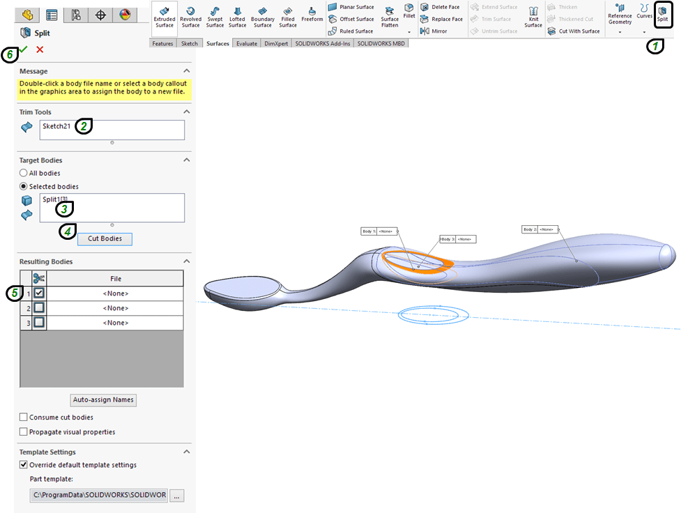
Split the part with the top plane sketch previously created, again without consuming the cut bodies as shown:
STEP 39.
Add more design features and on the top plane create another sketch made of an ellipse linearly multiplied 7 times as shown:
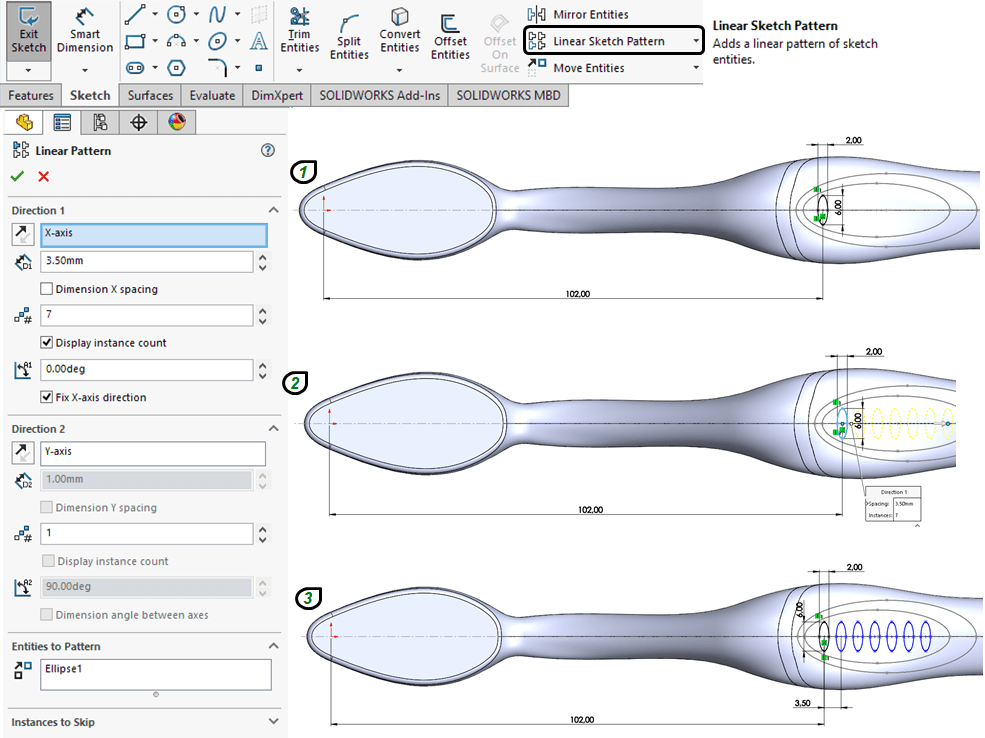
STEP 40.
Click on the Split icon and cut the inner long ellipse part with the 7 small ellipses without consuming the cut bodies as shown:
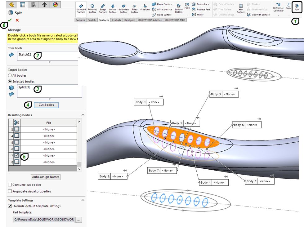
STEP 41.

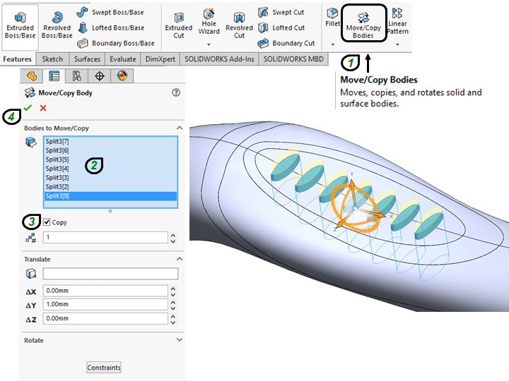
In the Insert menu, go to Features and then click on “Move/Copy…” icon to add more thickness on the 7 small ellipses.
Or alternatively, you can even customize your Solidworks Features tab by directly adding the “Move/Copy Bodies” icon into the features ribbon.
STEP 42.
Add the 1st Fillet on the front side cut as shown:
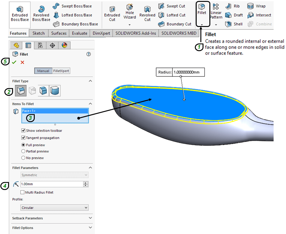
STEP 43.
You can now continue to add the rest of the fillets. But before to do that, in the Model Tree it is easier to Temporary Hide the Feature Called “Body-Move/Copy1” and also the 7 small ellipses as cut bodies. This will only show you the right edges where you can put fillets. Click on the Fillet icon, enter the value of 0,25mm and select the edges as shown:


Repeat the “Fillet” creation for the rest o the edges individually.
Put the same 0,25mm Fillets on the outer cut-bodies as well.
Unhide the Body-Move/Copy1″ and add 0,25mm fillets on each of the 7 elliptical protrusions.

STEP 44.

Again, for more structure in Model Tree, select all Fillets and add them in one folder.
STEP 45.
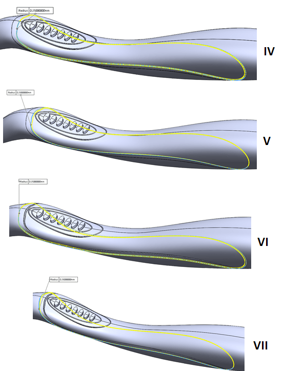
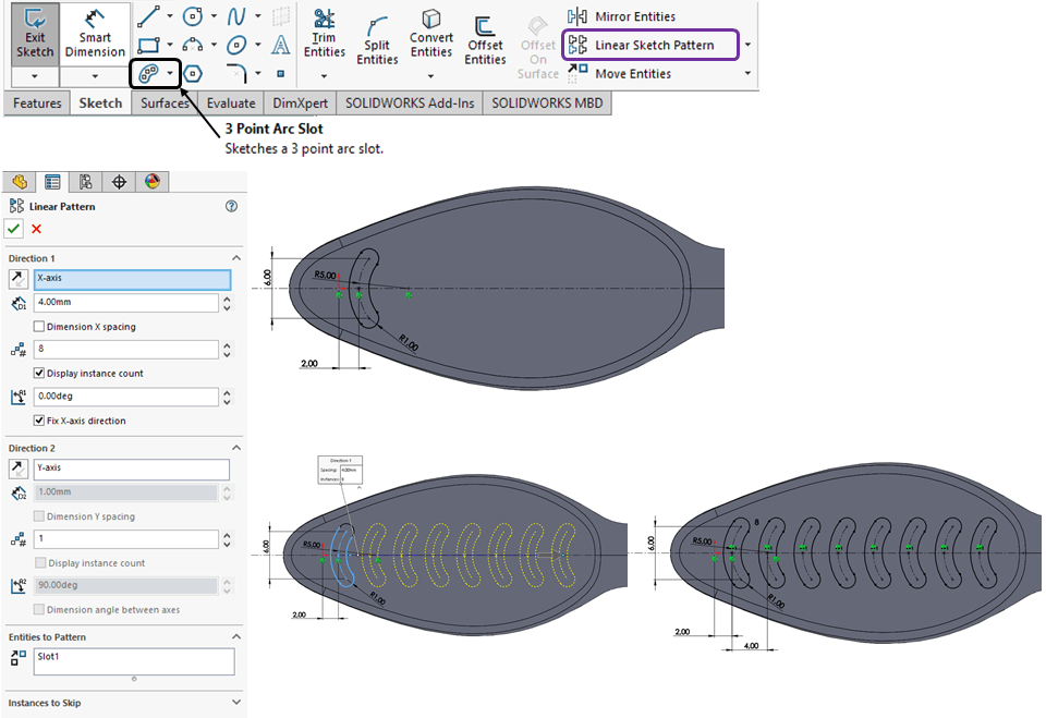
Add some more protrusions in the backside. For this on TOP plane, create a sketch made of 2 different slots created as 3point Arc Slot. Start with the front side and multiply the slot 8 times, as shown:
Continue by adding the 2nd Slot in similar way, but use different dimension and multiply it 7 times, as shown:

STEP 46.
In the Features tab, click on “Extruded/Boss/Base” icon and extrude the previously create sketch as backside protrusions as shown:

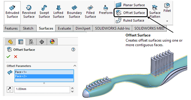
STEP 47.
In Surfaces tab, click on Offset Surface icon enter 1mm as value and select the 2 backside surfaces as shown:
STEP 48.
Now click on Split icon and this time activate the option to consume the cut bodies as follows:

Hide the Offset Surface feature and the part should now look like this:
STEP 49.

Create a circle of Ø2,5mm in the middle of a sketch on the flat area on brushing side as shown:
STEP 50.
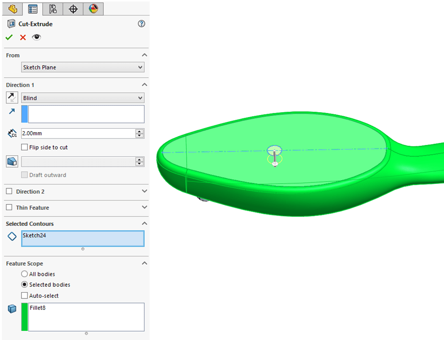
Create a 2mm deep Cut Extrude using the sketch from the previous step, as shown:
STEP 51.

On the bottom surface of the previous cut-extrude, create a sketch with a concentric circle of Ø0,35mm and a short construction horizontal line.
STEP 52.
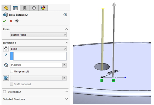
Click on Extruded Boss icon and create 15mm long body but leave the option “Merge result” deactivated.
STEP 53.
To add the rest of the brushing threads, everything which need to be done is to reuse the middle cut-extrude from Step 50 and the Extruded boss from Step 52 and multiply them on the entire brushing area. To do this, first create a sketch using the bottom edge of the cut-extrude, therefore just click on “Convert Entities” icon and select the edge as shown:
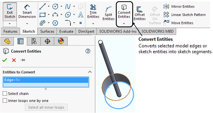
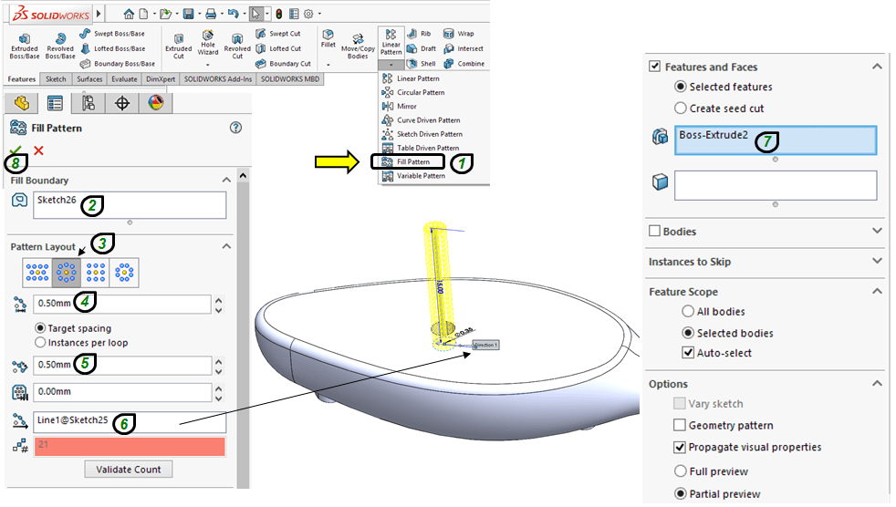
STEP 54.
Now the area defined by the previously converted edge, can be filled with a pattern of threads similar with the one created at Step 52. In the Features tab, click on “Fill Pattern” icon and follow the settings as shown:
STEP 55.
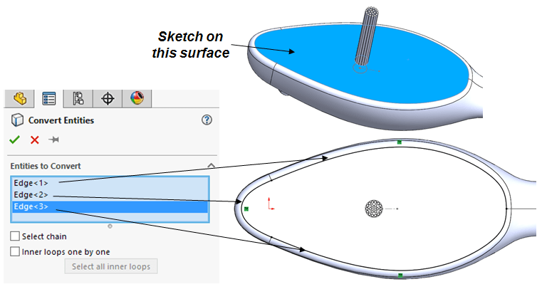
In the similar way it goes for the rest of the cut-extrudes in the brushing area. So, create a sketch on brushing face and convert the entities as shown:
STEP 56.
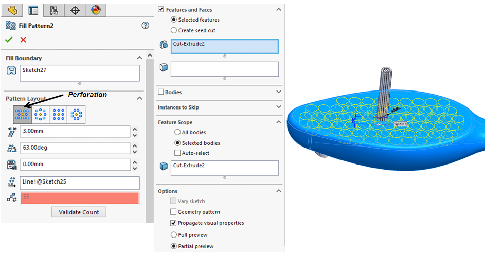
Click on “Fill Pattern“ icon and multiply the cut-extrude on the entire brushing area as shown:
STEP 57.
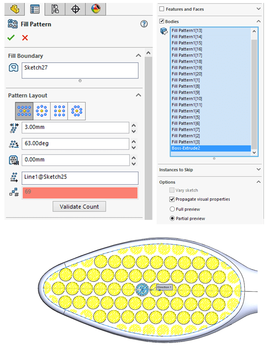
Repeat the procedure with the same pattern parameters like done at Step 56 but this time propagate the threads bodies as shown:
STEP 58.
As last design adjustment, in the Features tab click on the Delete/Keep Bodies icon (if this icon in not in your features ribbon you can always find it in the Insert menu like I showed above at STEP 41.) Then pick the bodies which need to be removed as shown:
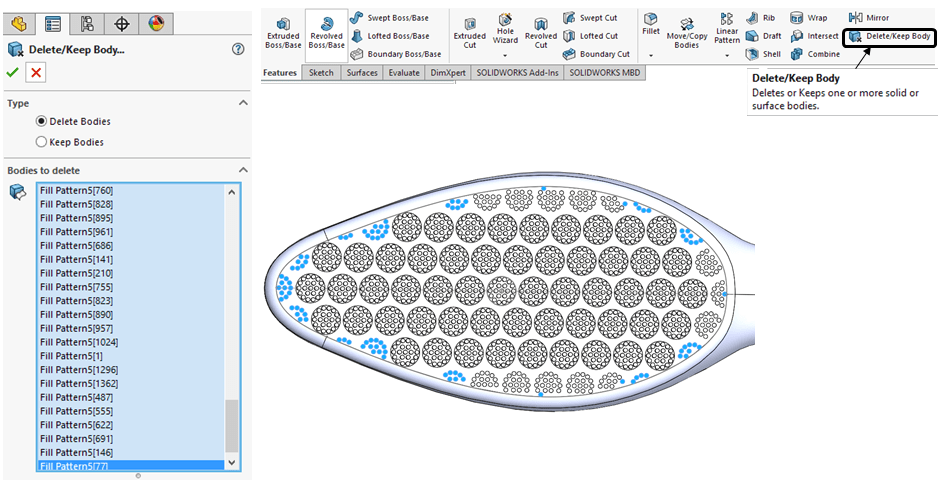
STEP 59.
Finally you can add a specific material and color as shown:
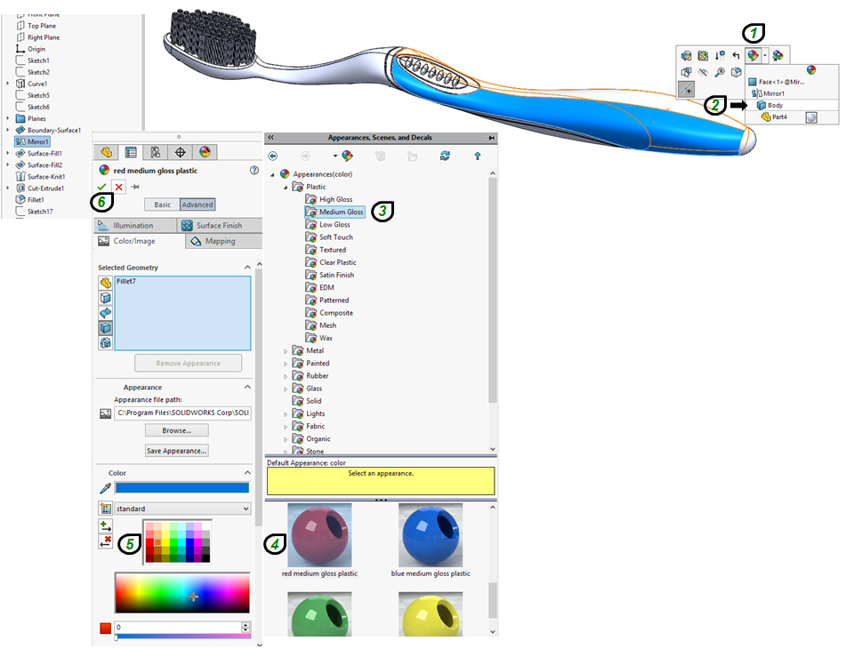
STEP 60.

If you want to reuse the same color it is simply to play with copy & paste approach by clicking the appropriate icons related to Appearance.
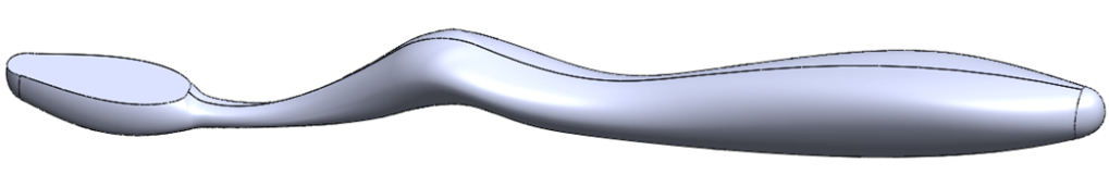
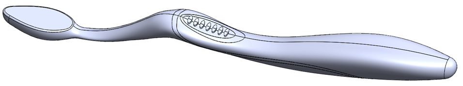
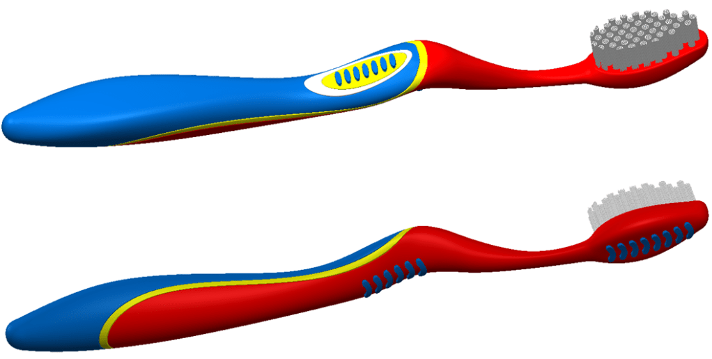
FINAL STEP
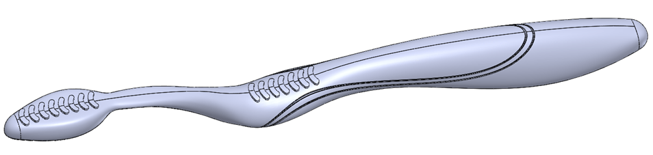
The final Tootbrush should look like this:
This work is also available as video version on my YouTube Channel as embedded below:

I really like the way you explain things; it’s evident and concise.
LikeLike
Yes indeed, I do my best share complex things in as simple as possible way and easy to understand. Thank you very much for reading.
LikeLike
Best blog ever! Thank you for the content, my friend!
LikeLike
You’re welcome. I am glad you find my stuff insightful. Likewise thanks for reading. I appreciate you. 😉
LikeLike