Objects made as an assembly of more than 1 component, in order to be functional besides a clearly specified form each component, must have at least 1 clearly specified orientation (parallel, perpendicular or angular). For the parallelism and perpendicularity the orientation is quite simple to understand , it is either at 0° or at 90°, but in case of angularity we deal with values which are anything else in between.
In a mechanical drawing of a part, angularity tolerance allows the designer to specify the degree to which the orientation of an angled part feature may vary. The angularity symbol is often used to insure that the part can properly mate with another but if this sounds more like a literally controlling the angle of an element versus a reference measured in degrees (°) it is in fact NOT the case. Angularity tolerance is a different thing than the Angle tolerance. So let´s see below: What exactly is the Angularity?
Description
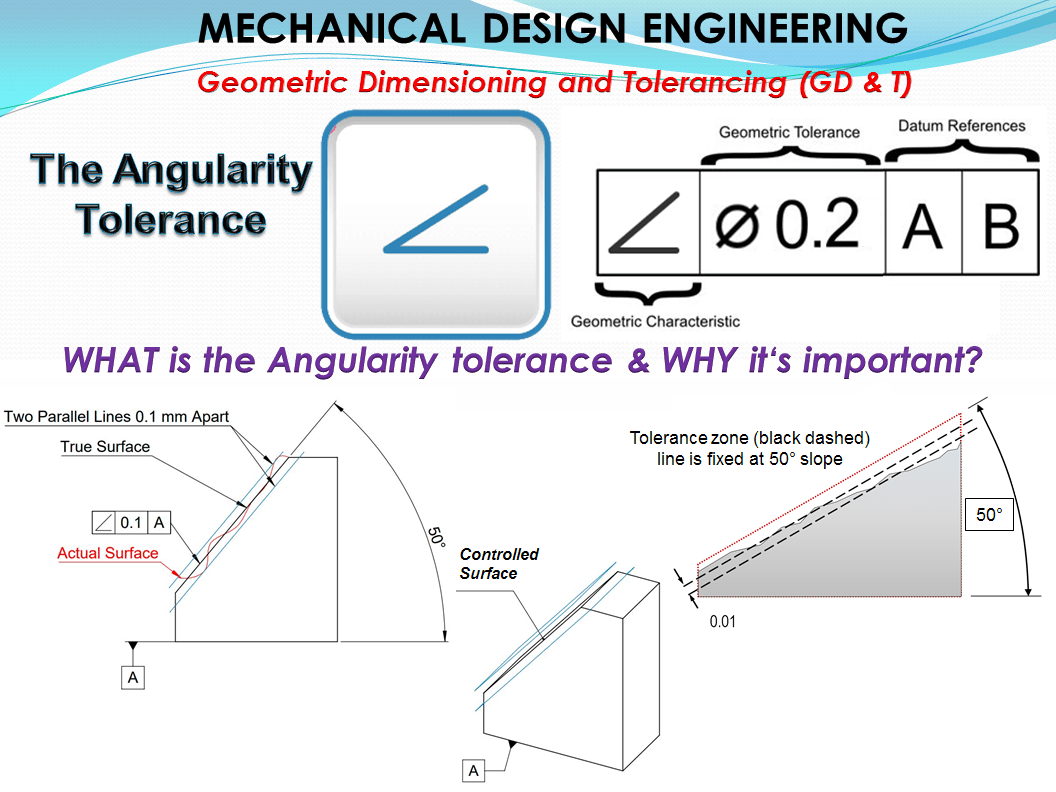
Angularity tolerance specifies a tolerance zone defined by two parallel planes at the specified angle other than 0 and 90 degree from a datum plane or axis within where the surface or the axis of the feature must lie.
NOTE : The angularity tolerance does not directly control the angle variation and should not be confused with an angular dimension tolerance such as ± 5°. In fact, the angle, for now, becomes a Basic Dimension, since it is controlled by the geometric tolerance.
The angularity tolerance indirectly controls the angle by controlling where the surface can lie based on the datum. See the tolerance zone below for more details.
The angularity tolerance is the general case of a orientation (direction) tolerance. Therefore what applies to parallelism and perpendicularity applies analogously to the angularity as well.
The symbol of angularity tolerance is an asymmetrical angle entered as one horizontal line and a slash line both coincident at their left end points (as shown in figure 1.)
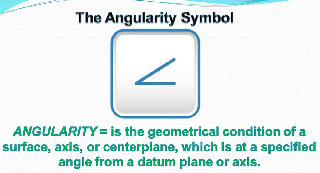
This symbol is specified in the left compartment of the feature control frame and it is used to describe a angular orientation of one referenced feature to a datum surface or line.
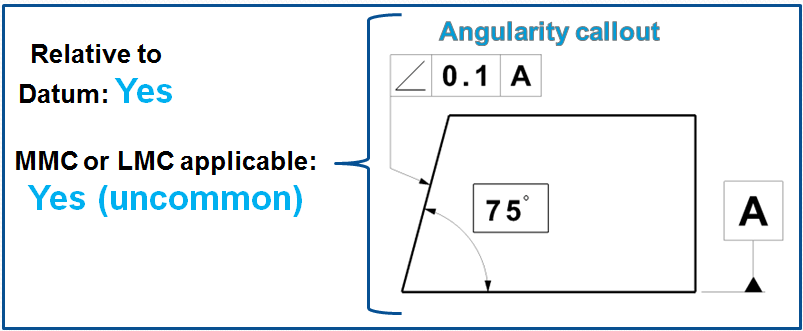
The Tolerance call out: while for the Parallelism and Perpendicularity the nominal angle between the reference and the tolerated element is clear, in case of angularity the entry must be given by the 3 elements as follows:
- Tolerance value in mm (or inch) but not in degrees (°)
- Reference datum (for the purpose of accurate testing a reference system-usually made of 2 datums – is often used)
- Nominal angle in degrees (°) as theoretical value in a rectangle.
If the rectangle for theoretical value of the nominal angle is missing, then the angle is subject of general tolerances. The Angularity tolerance is as always the distance in mm (or inch) between the tolerance limits.
Tolerance zone
Maximum Material Condition or axis control can also be called out for angularity although the use in design and fabrication is very uncommon since gauging a hole or pin at an angle is difficult. When angularity is called out on an axis, the tolerance zone now becomes a cylinder around the referenced axis at an angle to the datum. The page on Perpendicularity goes into this type of reference in further detail since it is more common with perpendicularity.
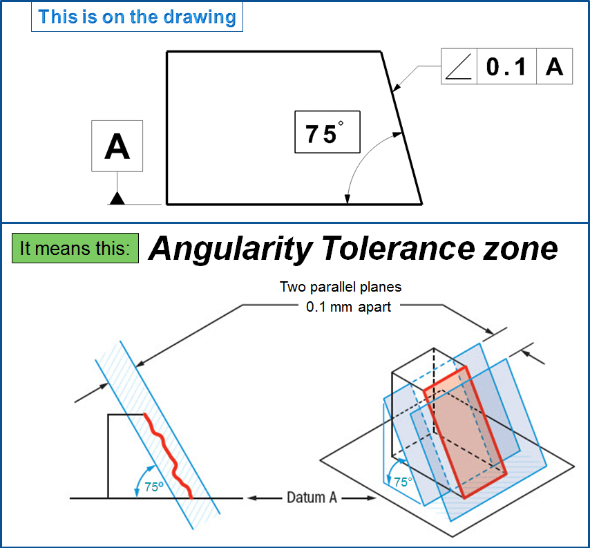
Two parallel planes or lines which are oriented at the specified angle in relation to a datum. All points on the referenced surface must fall into this tolerance zone.
Angularity does not directly control the angle of the referenced surface; it controls the envelope (like flatness) that the entire surface can lie.
Where an orientation tolerance feature control frame is placed associated with a diameter or width dimension, the tolerance controls the orientation of the cylindrical or width-type feature. Unmodified, the tolerance applies RFS (Regardless of Feature Size) and establishes a central tolerance zone, within which the feature’s axis or center plane shall be contained.
The Y14.5 standard also allows the orientation of an axis to be controlled within a parallel-plane tolerance zone. Since this would not prevent the axis from revolving like a compass needle between the two parallel planes, such an application usually accompanies a larger positional tolerance.
If a “diameter” symbol precedes the angulation tolerance value then, the central tolerance zone is bounded by a cylinder having a diameter equal to the tolerance value. This control is more like a positional tolerance, except the orientation zone is not basically located from the datums.
A positional tolerance also controls orientation for a feature of size to the same degree as an equal orientation tolerance. Thus, for any feature of size, an orientation tolerance equal to or greater than its positional tolerance is meaningless. Conversely, where the designer needs to maximize positional tolerance while carefully protecting orientation, a generous positional tolerance can be teamed up with a more restrictive orientation tolerance.
When the Angularity tolerance is used?
This approach applies to all 3 Orientation Tolerance (parallelism, perpendicularity and angularity). The features controlled by these type of geometric tolerance are:
- plane (including line elements);
- cylinder;
- width;
- revolute-radial element (cone)
In many cases, a secondary datum may be added for additional control. The illustrated parts are simplified abstracts, meant to show only the orientation control. On real parts, the orientation tolerances often accompany positional or profile tolerances.
Angularity helps control any feature that is at an angle to another datum surface. Anytime you have a critical feature which mates with other parts at an angle, angularity can be used to help control the angle and flatness of the mating surfaces. Many stamped parts that have bent features use angularity to ensure that the 3D surface formed by the stamping operation that is formed always is controlled and encased in a tolerance zone.
For instance, if you have a stamped part that had to hook into another part at an angle of 30 degrees, you would want to call out angularity on the “bent” feature to ensure that it is always at its proper orientation. If you did not use angularity you would have to both tighten the angle tolerance of the part and the thickness tolerance of the referenced surface.

Most drawings have a tolerance block or a general note that includes default plus and minus tolerances for angles. This default tolerance applies to any angle explicitly dimensioned without a tolerance. The angle between the depicted features shall be within the limits established by the angle dimension and the default angle tolerance. The default tolerance can be overridden by attaching a greater or lesser tolerance directly to an angle dimension. Either way, since neither feature establishes a datum for the other, the angular control between the features is reciprocal and balanced. The same level of control occurs where center lines and/or surfaces of part features are depicted on a drawing intersecting at right angles. Here, an implied 90° angle is understood to apply along with the default plus and minus angle tolerances. As before, there is no datum hierarchy, so all affected angular relationships are mutual. The type of plus and minus angle tolerances just described does not establish a tolerance zone, wedge shaped or otherwise, to control the angulation of either feature. Be careful not to misinterpret Y14.5’s Fig. 2-13, which shows a wedge-shaped zone controlling the location of a planar surface. Because it’s still possible for the surface to be angled out of tolerance within the depicted zone, the “MEANS THIS” portion of the figure adds the note, its angle shall not be less than 29°30′ nor more than 30°30′. (for more details consult the Y 14.5 standard).
In Fig 4. is shown how angularity is used for a better control of the part.
In case of Angularity example 1: Tightening the angle and/or the thickness are required if angularity is not called out.
For Angularity example 2: A simple call to angularity now ensures that the stamped surface now has both proper angle and flatness. The angle must be a basic dimension but now allows your part thickness to open up more. (Note this drawing is unconstrained and would need additional size dimensions to be accurate.)
Remember!! – You are not controlling the angle with angularity – you are controlling the surface to fall within the specified dimensional tolerance in millimeters!
The most frequent Angularity Examples of use are as follows:

a) 2 planar surfaces – the tolerance zone of the front surface has an angle of 75° versus the bottom reference datum A. The flatness of the front surface is determined. To measure this, the work piece can be hold for instance with the surface (datum) A on a measuring head, slewed at 75° and then the front surface scanned with a dial gauge.
b) hole angularity – the tolerance zone in this case is limited by 2 planes as well. For the checking clearness it is appropriate to indicate the 2nd reference datum. Which of the 2 reference elements serves as primary reference, depends on which one is considered to determine the position of the part. The boundary planes of the tolerance zone are in this example perpendicular to datum B.
c) 2 axis angularity – the reference is the axis datum A. The tolerance zone is again limited by 2 planes. The intersection point of the 2 axis is not defined, meaning that the cross-hole is allowed to slide sidewise.
d) tubular tolerance zone and reference system – the same thing like for example c) also applies here, only the direction of the circular tolerance zone is defined but not its position (which results from the measurement), namely the part is slewed at 75° versus datum A and is parallel to datum B.
If the position either for the case c) or the case d) should be specified, then the position tolerance will be entered in the same place.
The difference between the Angularity Tolerance and Angle tolerance
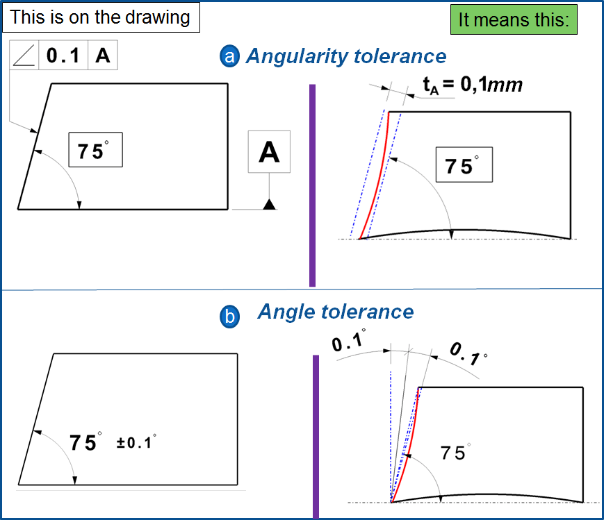
The Angularity tolerance is given in milimeters (mm) or inch. This includes the Angle tolerance in the same time; practically speaking this is quite common. (the Surface may be 1/10mm out of nominal Angle).
The Angularity tolerance zone as shown in fig. 6. a constraints also the Form of the tolerated flank (Straightness perpendicular to tolerance zone such as Flatness). The following rule applies to all 3 orientation tolerances:
“In each direction tolerance there is a flat form tolerance included; meaning that the straightness deviation of a tolerated element (perpendicularly measured on tolerance zone) can not be bigger than the the direction tolerance t; Correspondingly this is also valid for flatness deviation of tolerated planes. The additional entry of a Straightness, respectively a flatness tolerance makes sense only when the Form tolerance is smaller than the direction tolerance”
Yet, in Angularity case the form deviation of the reference elements is not restricted.
The Angle tolerance is given in degrees (°). As shown in the example 6-b both flanks are treated in the same time, meaning that there is no difference in this case between the tolerated element and the reference datum. The direction of each flank will be given by one of the reference datums, namely by real straight lines respectively by planes according to the Least Material Condition (LMC) and for holes by the boundary element. The form deviations in both cases fall out from the angle measurement.
The conversion between Angularity and Angle values
This is – because of the mentioned differences – only possible when the form deviations of the tolerated element which has a Angularity tolerance, are neglected. (In case of doubts when both values are the same, then the Angularity tolerance is the primary one to be considered for the workpart).
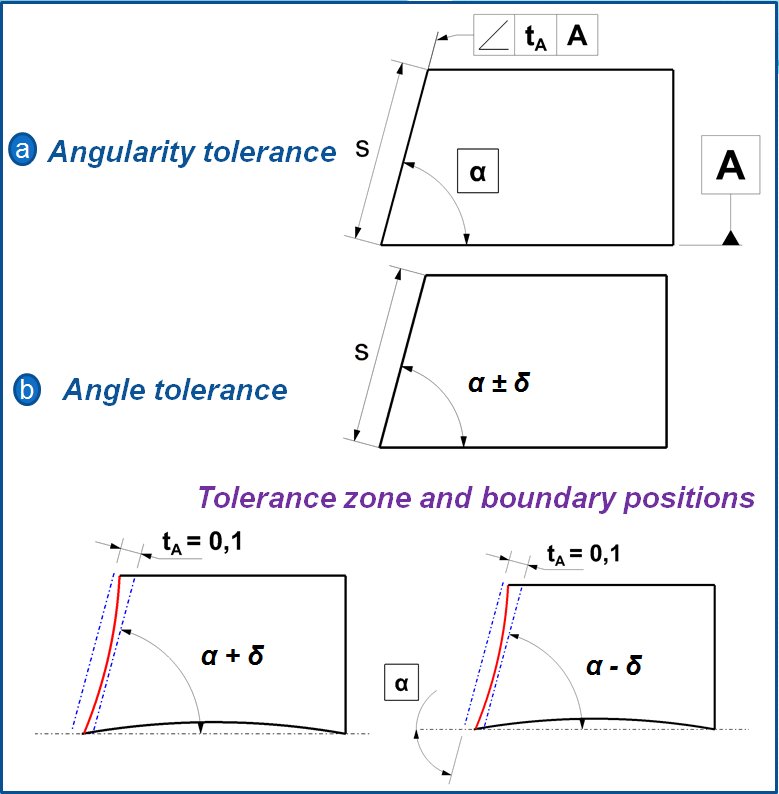
From Angularity tolerance to Angle tolerance – Fig. 7-a = From the tolerance tA and the flank lenght s (a) results 2 boundary locations of the flanks one with nominal angle at +δ deviation and another one at -δ. With a sufficiently accurate approximation δ =tA/s (in radial measurement) the comparable Angle tolerance is named α±δ.
From Angle tolerance to Angularity tolerance – Fig 7-b = with an unsymmetrical developed tolerance the Angle tolerance is initially defined as α±δ. From both possible boundary locations results the Angularity tolerance tA= s*tanδ. The value of s being the position of tolerated flanks; in such a case it is generally usefull to choose the shortest flank.
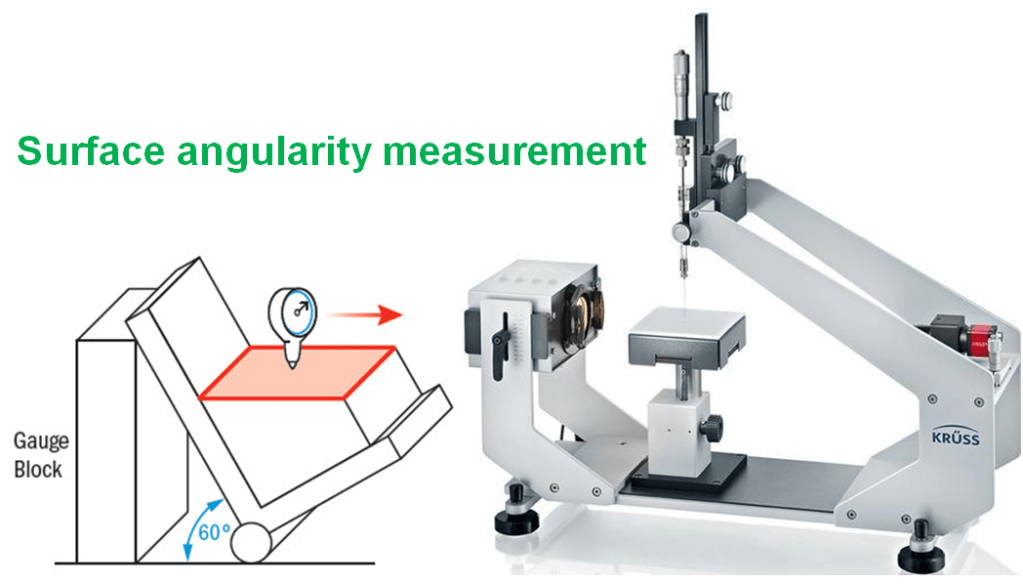
Gauging / Measurement.
Angularity is measured by constraining a part, usually with a sine bar, tilted to the reference angle, so that the reference surface is now parallel to the granite slab. By setting the part at an angle the flatness can now be measured across the now horizontal reference surface. The entire variation must not fall outside the tolerance zone.
Relation to Other GD&T Symbols.
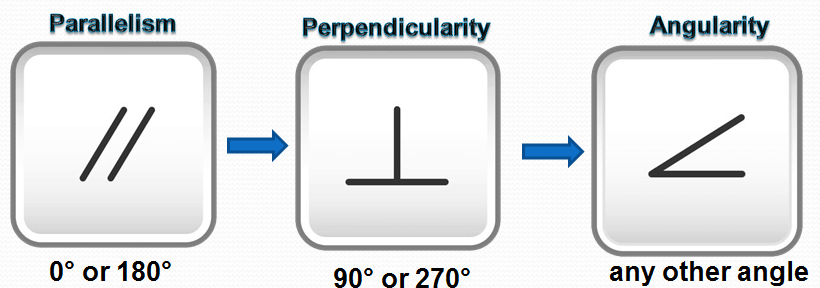
Perpendicularity and Parallelism are actually refined forms of Angularity. Perpendicularity describes angularity at 90° and parallelism describes it at 0°. All of these are profiles of orientation and are used in the exact same way. They also can be used with control of an axis under maximum material condition, although perpendicularity is usually the only one you will ever see with this callout.
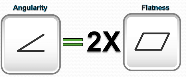
Orientation GD&T Symbols are also closely related to flatness when the surfaces are is flat planes. When you call out any of the orientation symbols, flatness is implied (you are measuring a surface variation between two parallel planes = Flatness) However the biggest difference is that orientation callouts are measured with respect to a datum, where flatness is not.
Final Notes
Datum Relationship: Since all of the orientation symbols (Angularity, Perpendicularity, and Parallelism) are referenced to a datum – essentially the tolerance is not measuring a specific surface or feature on its own. You are measuring the relationship of one feature or surface with respect to another feature. If one feature is out – both surfaces could be incorrect.
Maximum Material Condition: Maximum material condition can also be used in a similar method of perpendicularity. Although MMC is usually for pins or holes which need to be perpendicular to a reference surface, so it is not commonly used on angularity. See Perpendicularity for more details about Gauging and Calling out MMC on an orientation symbol.
Dimensional Angularity: As stated before: 2-Dimensional references can also be used with angularity to ensure that an angle is met around a round or complex feature. If you wanted to specify the angle of a cone, for example, the angularity would apply to each line element along that cone referenced to the bottom of the cone.

Leave a comment