Let’s Design the Thor Hammer with SOLIDWORKS
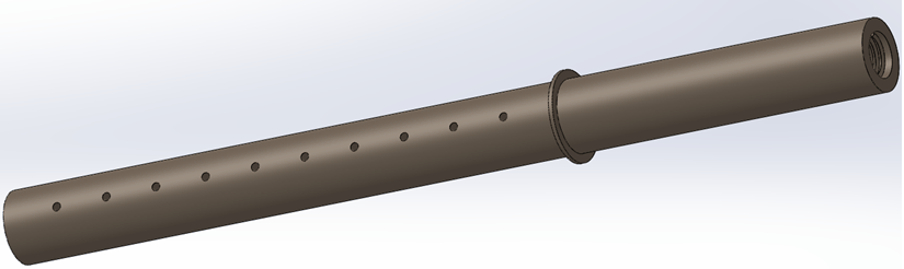
PART 1 – Handle
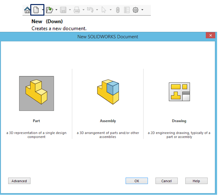
STEP 1.
Create New Part
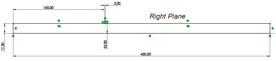
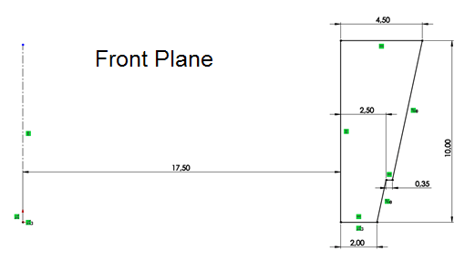
STEP 2.
On the Right Plane draw the sketch as shown:
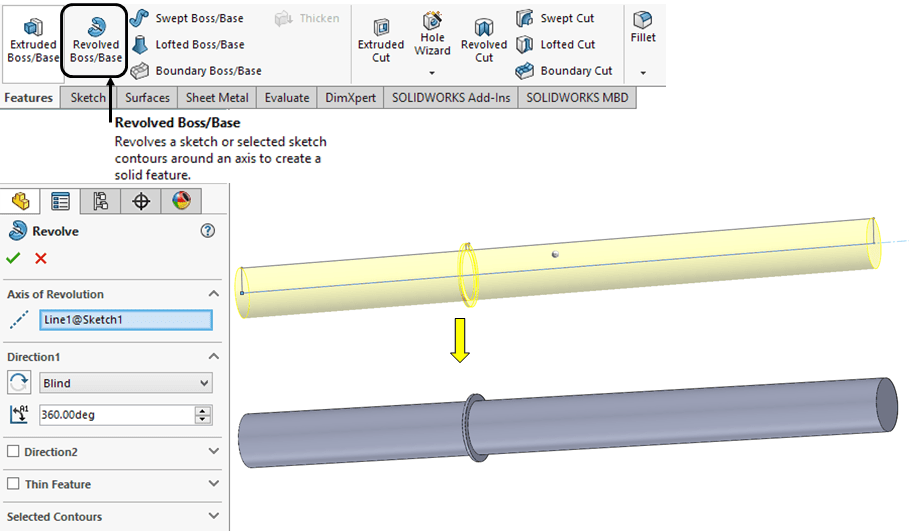
STEP 3.
In Featrues toolbar, click on Revolved Boss/Base icon and revolve the sketch completely.
STEP 4.
On Top Plane create a sketch as shown:
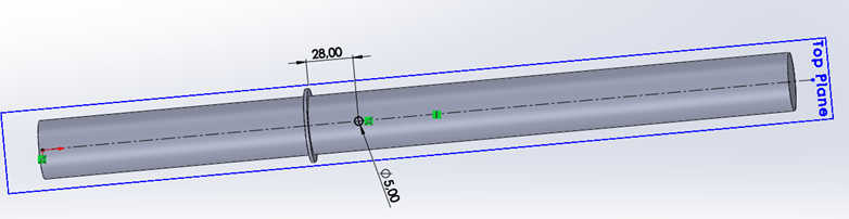
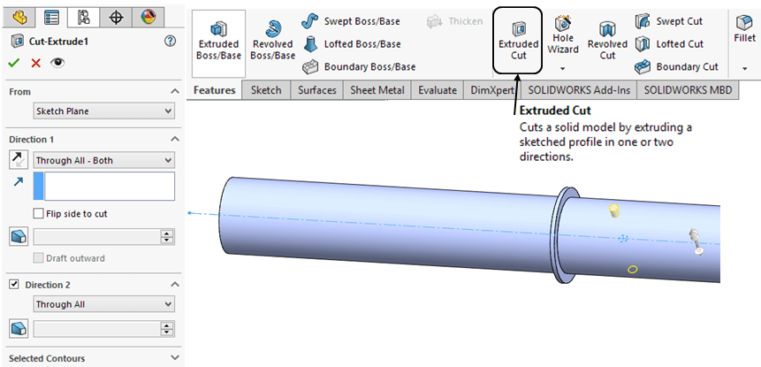
STEP 5.
In Features toolbar click on Extruded Cut icon and extrude the sketch through all in both sides as shown:
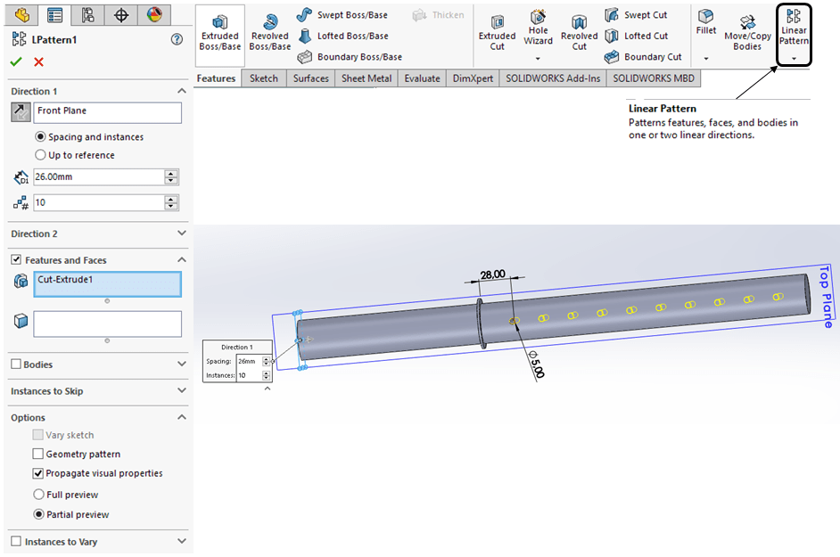
STEP 6.
In Features toolbar click on Linear Pattern icon and create a pattern with 10 holes as shown:
STEP 7.
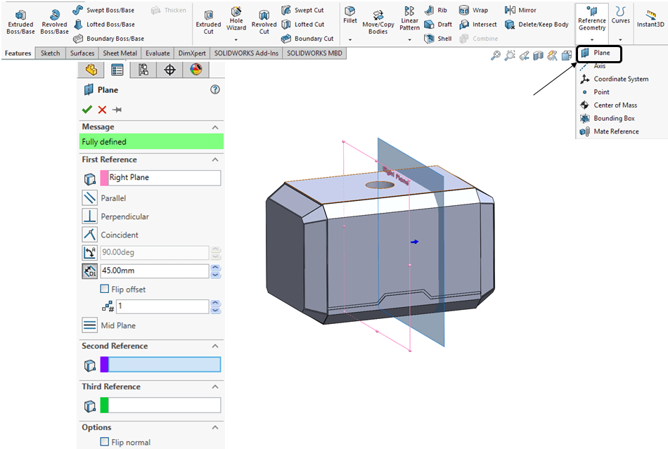
On the top side of the part create a reference plane with an offset of 4mm from the top surface as shown:
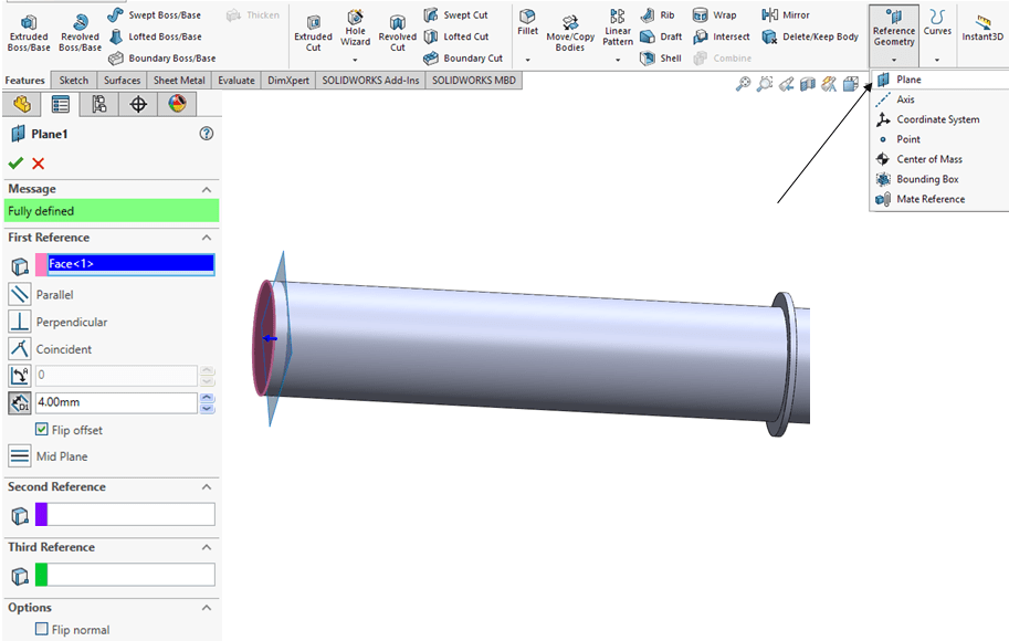
STEP 8.
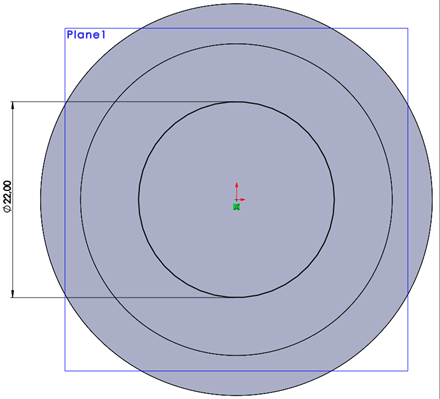
On the new ref. Plane from the previous step, sketch a circle of Ø22mm.
STEP 9.

In the Features toolbar click on Extruded Cut icon and cut the volume out in 2 directions, 1st with 20mm downwards and 2nd up to next upwards, as shown:
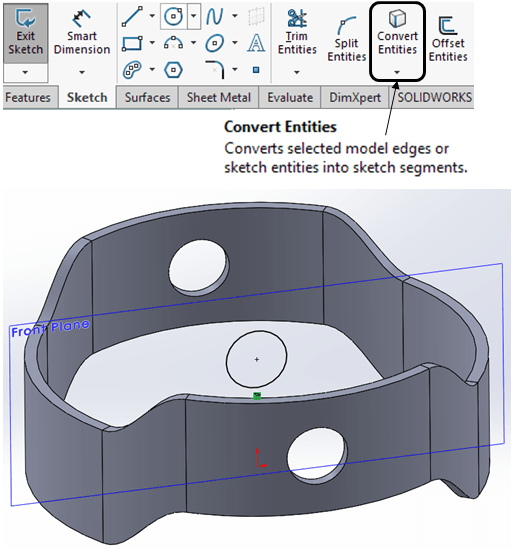
STEP 10.
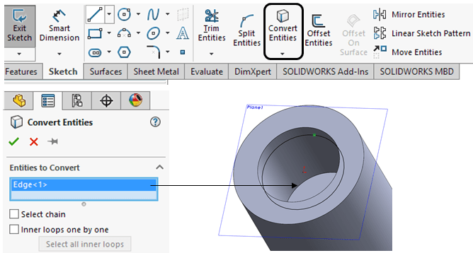
On the same ref. Plane create a new sketch by converting the bottom edge on the plane as shown:
STEP 11.
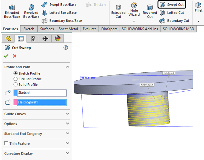
In Features toobar click in the Curves drop-down menu click on Helix and Spiral icon, select the previous sketch and enter the spiral parameters as shown:

STEP 12.
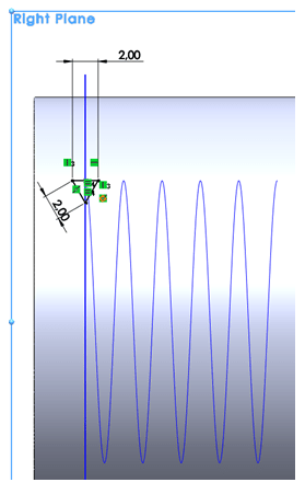
Click on the Right Plane and sketch a isosceles triangle of 2mm connected with the spiral as sweep profile, as shown:
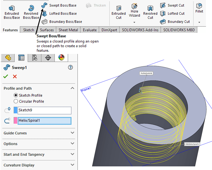
STEP 13.
In the Features toolbar click on Swept Boss/Base, use the isosceles triangle as profile and the Spiral as Path. An inside thread is then created as shown:
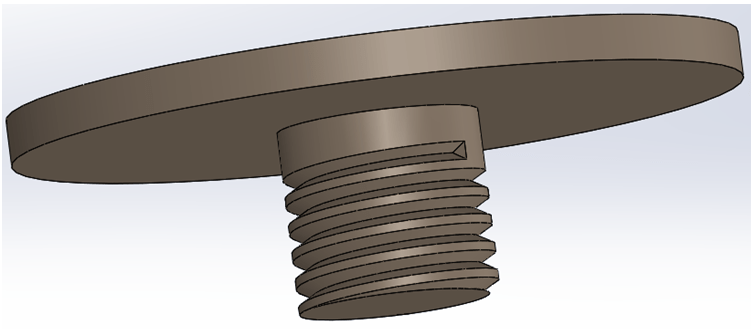
FINAL PART
Apply Appearances, for instance “Polished Nickel” and the final part looks like this:
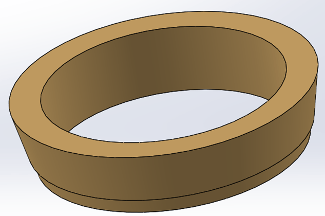
PART 2 – Golden Ring
STEP 1.
On Front Plane create a sketch as shown:
STEP 2.
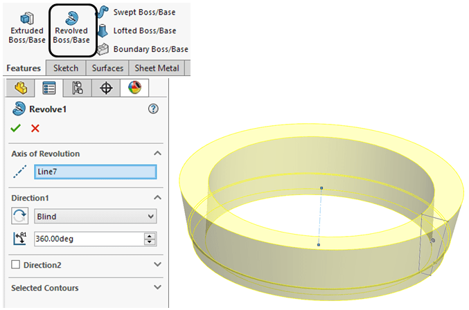
In Feature toolbar click on Revolved Boss/Base icon and revolve the sketch completely.
FINAL PART
Apply Appearances, for instance “Polished Gold” and the final part looks like this:
PART 3 – Handle Ring
STEP 1.
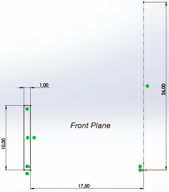
On the Front Plane sketch a profile as shown:
STEP 2.

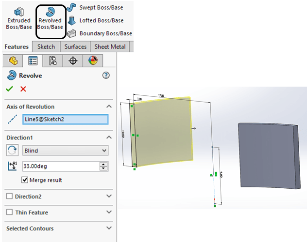
Partially revolve the previous sketch with 33deg
STEP 3.
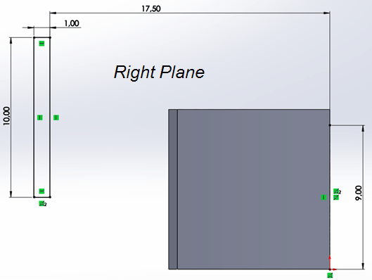
On Right Plane sketch the profile as show with the bottom line coincident with the middle point on the 9mm axis.
STEP 4.
Partially revolve the 2nd profile in with 33deg as shown.
STEP 5.
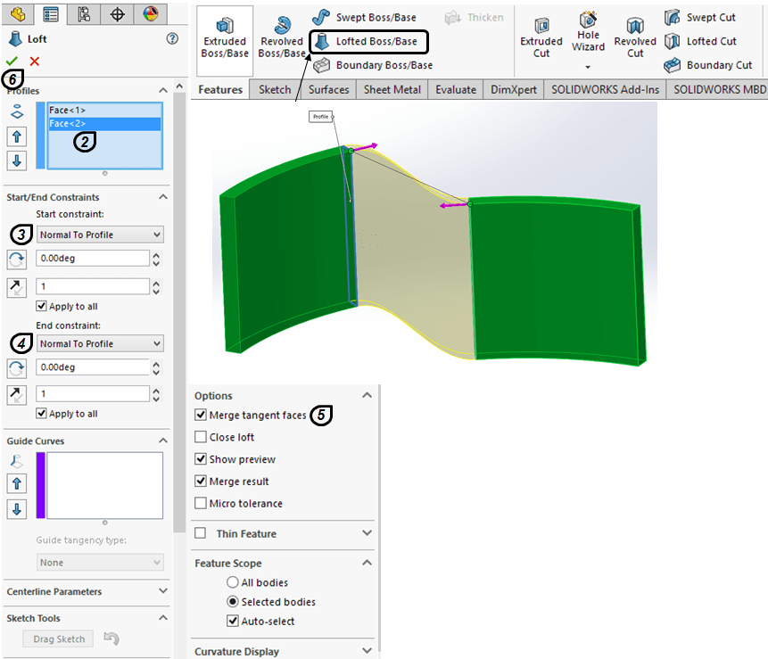
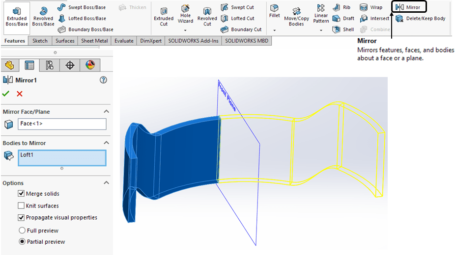
From Features toolbar click on Lofted Boss/Base icon and create a loft between the 2 partially revolved features. Enter the parameters as shown:
STEP 6.
Mirror the created body as shown:
STEP 7.
Mirror again everything as shown:
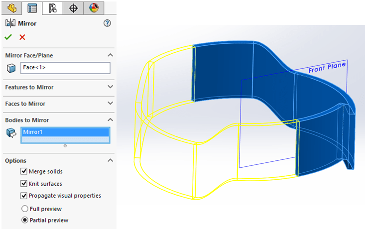
STEP 8.
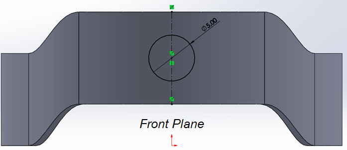
On Front Plane create a sketch with a Ø5mm circle
STEP 9.
With the previous sketch, cut the body through all on both sides as shown:
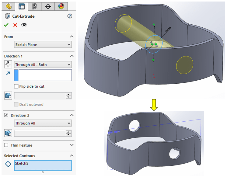
STEP 10.
On Front Plane create another sketch by simply converting the previous one.
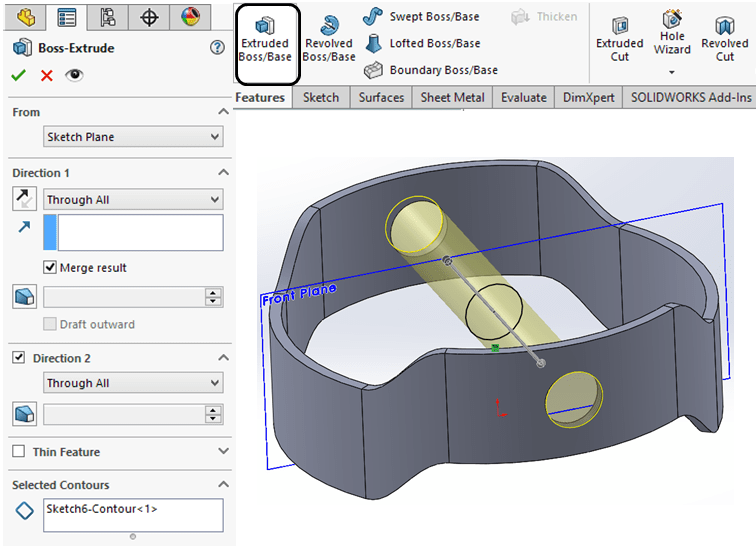
STEP 11.
With the previous sketch now create an Extruded boss through all on both sides as shown:
STEP 12.
On the outer edges apply a fillet of 1mm as shown:

FINAL PART
Apply Appearances, for instance “Satin Finished Gold” and the final part looks like this:

PART 4 – Bottom Cap
STEP 1.
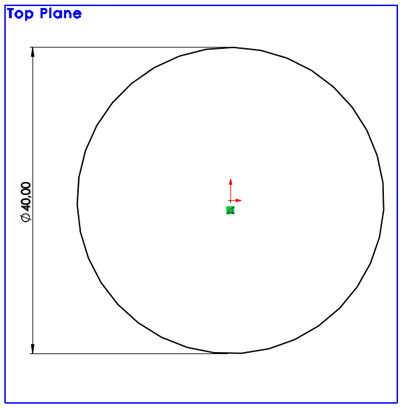
On Top Plane, sketch a circle of Ø40mm
STEP 2.
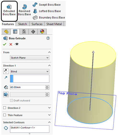
Extrude the circle with 60mm
STEP 3.
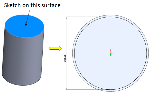
On top surface sketch a circle of Ø38mm
STEP 4.
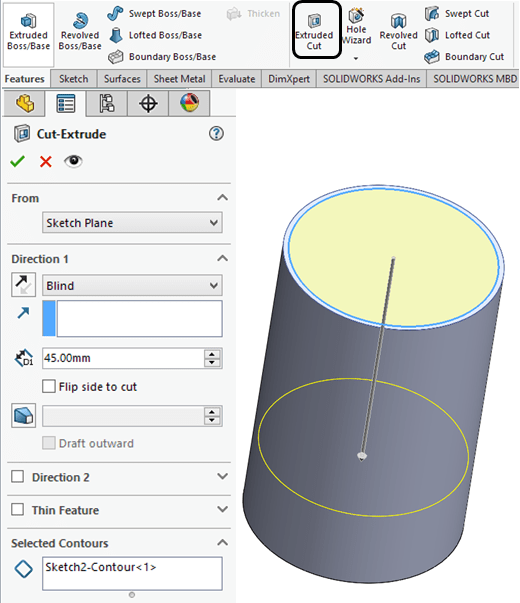
Do an Extruded cut on the inside with 45mm deep
STEP 5.
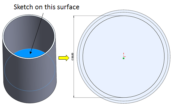
On bottom surface skech a circle of Ø35mm
STEP 6.
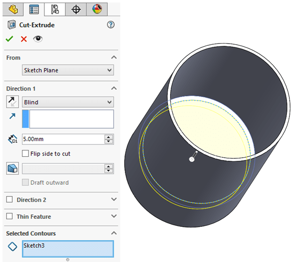
With the previous sketch, do an Cut-Extrude inwards 5mm deep
STEP 7.
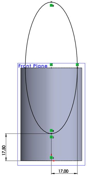
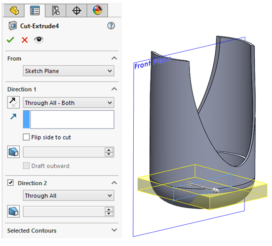
On Front Plane; sketch an Elipse as shown:
STEP 8.
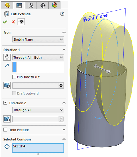
With the previousy sketched elipse cut the body through all on both sides.
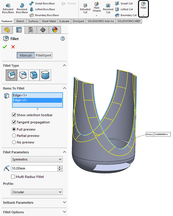
STEP 9.
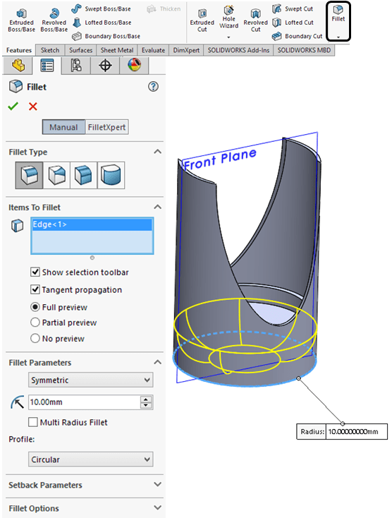
On the outer bottom edge add a fillet of 10mm.
STEP 10.
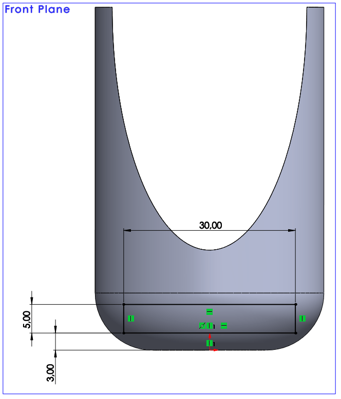
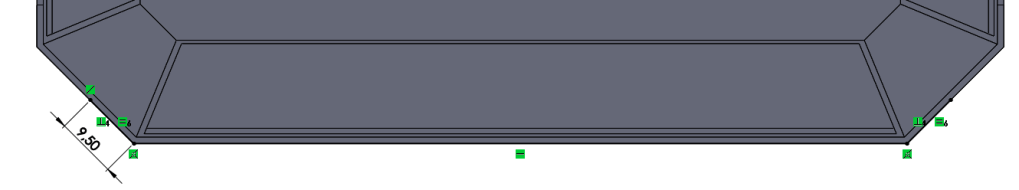
On Front Plane sketch a rectangle as shown.
STEP 11.
With the previous sketch cut the body through all on both sides.
STEP 12.
On the outer sidewise edges add a fillet of 10mm.
STEP 13.
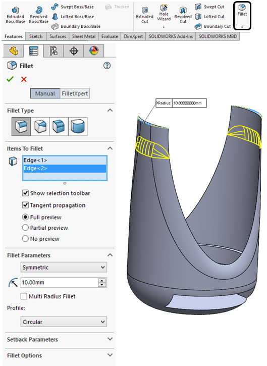
Add fillet on the top outer edges.
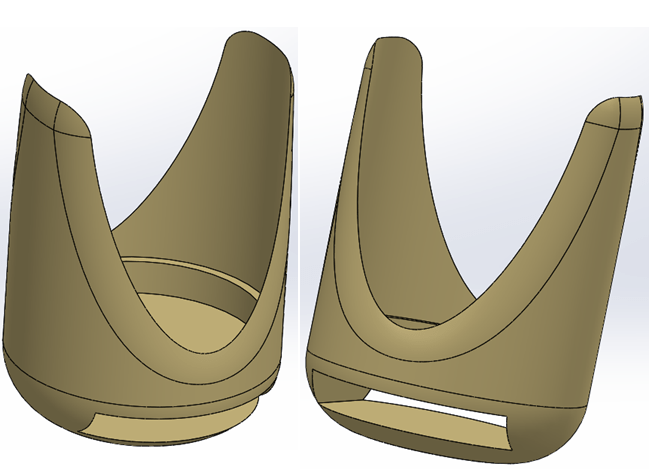
FINAL PART
Apply Appearances, for instance “Satin Finished Gold” and the final part looks like this:
PART 5 – Rubber Band
STEP 1.
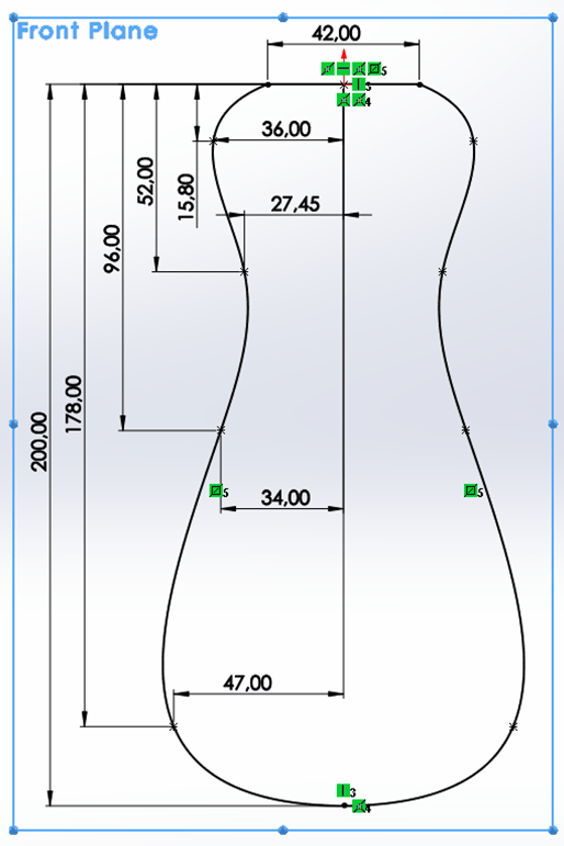
On Front Plane sketch the half-profile first using a spline with 6 points, and mirror it as shown.
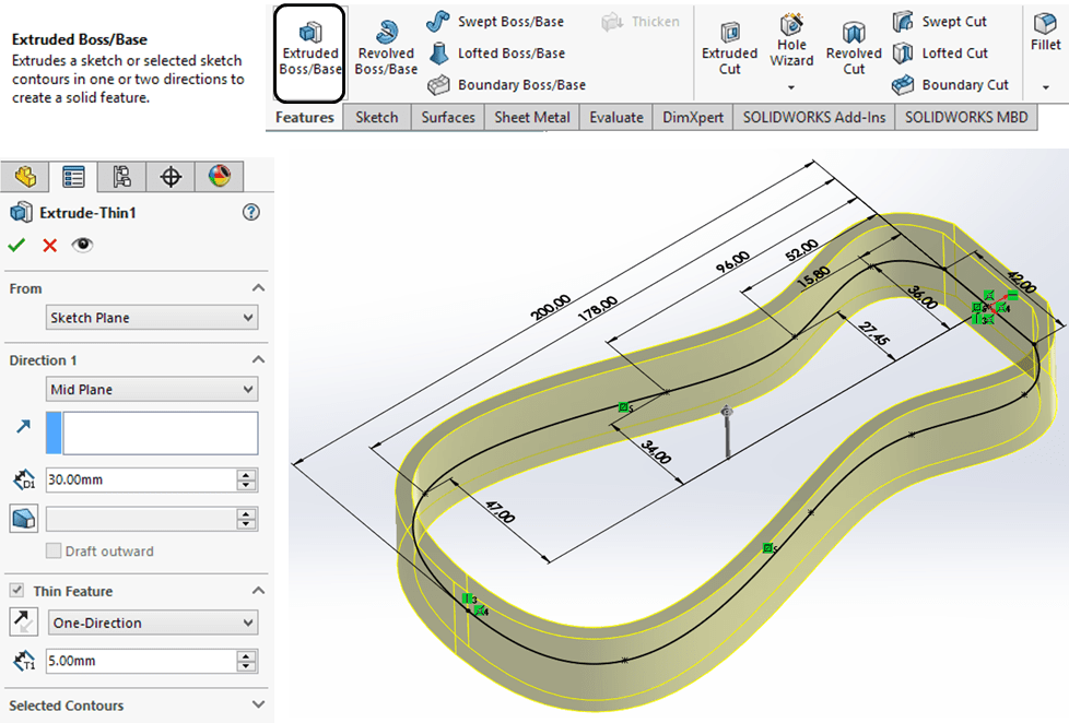
STEP 2.
Extrude the previous sketch as thin feature on One-Direction (Outward) with 5mm and by mid-plane with 30mm as shown:
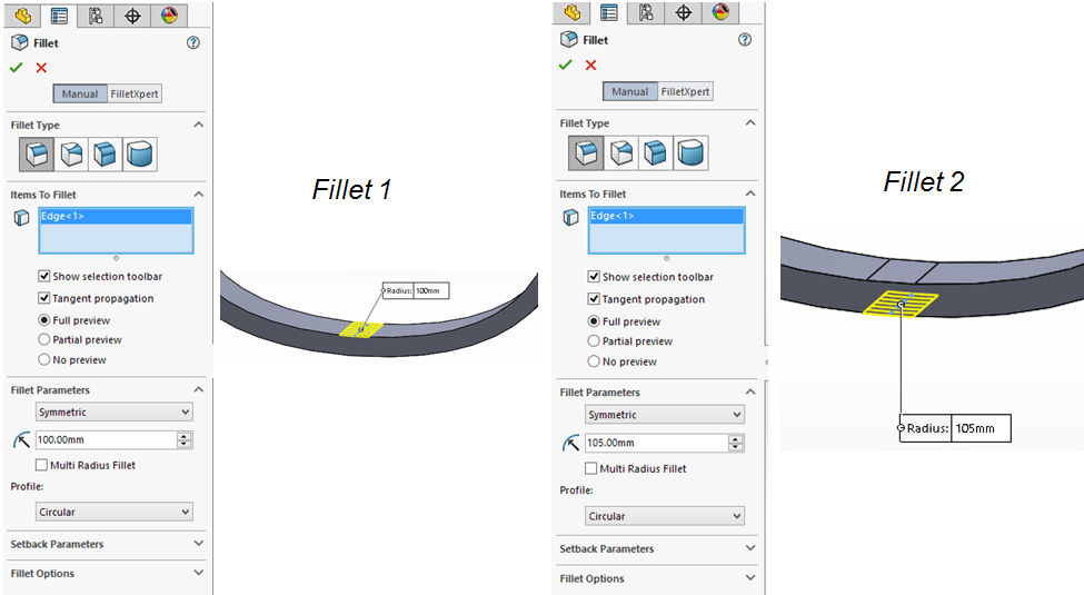
STEP 3.
Apply fillets on bottom side of the part as shown:
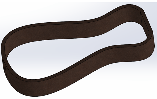
FINAL PART
Apply Appearances, for instance “Satin Finished Gold” and the final part looks like this:
PART 6 – Hammer Head
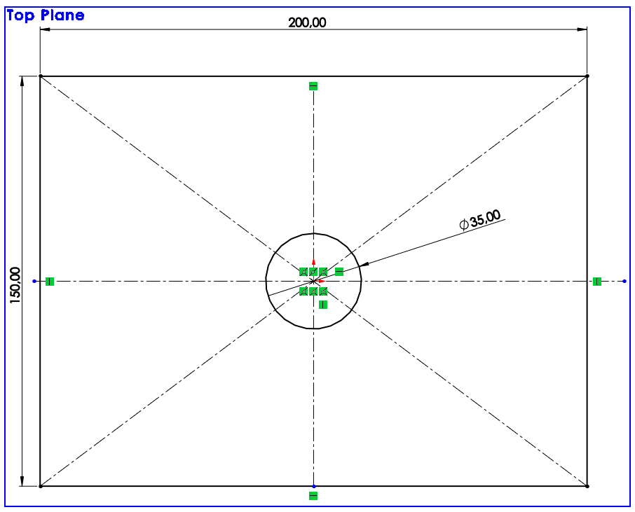
STEP 1.
On Top Plane sketch a center rectangle with a circle in the middle as shown:
STEP 2.
Extrude the sketch with 150mm on Mid plane direction

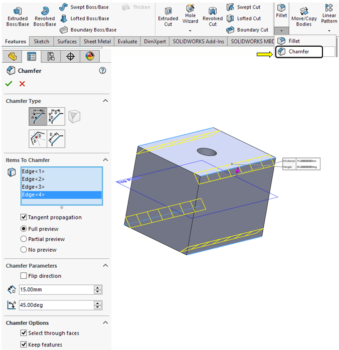
STEP 3.
Apply 15mm x 45deg chamfers on length
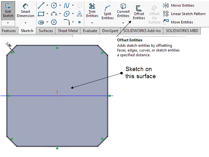
STEP 4.
Click on the front surface and sketch a new profile by offseting the edges of the main body with 1 mm inward.
STEP 5.
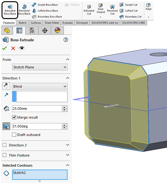
Extrude the front sketch with 25mm and use a inward draft of 31deg.
STEP 6.
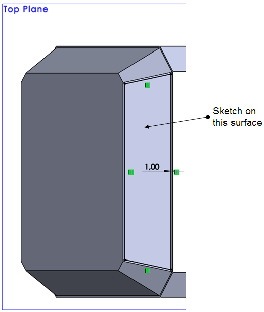
Click on one drafted surface and create a new sketch by offseting the main surface profile with 1mm inwards;
STEP 7.
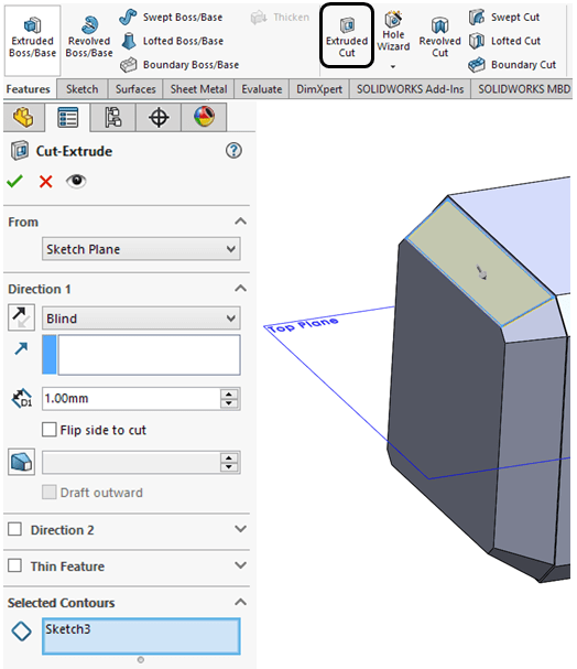
Extrude the previous sketch as a cut with 1mm deep;
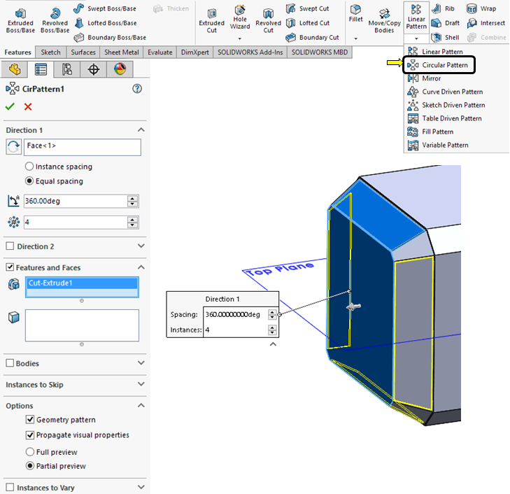
STEP 8.
On Feature toolbar, click on the little black arrow from the Linear Pattern icon and select the Circular Pattern frim drop down menu. Then Select the front face as Direction 1 and pattern the previous cut 4 times as shown:
STEP 9.
On the Features toolbar click on Mirron icon, select the Right Plane as Mirror plane and mirror the drafted boss, the cut extrude and circular parrtern as shown:

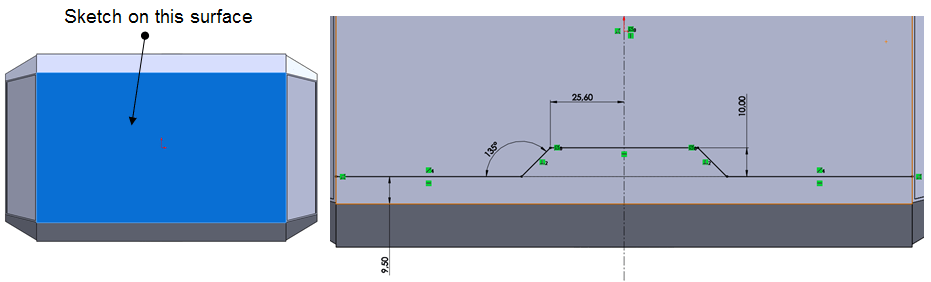
STEP 10.
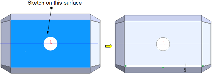
Select the sidewise surface and sketch the profile as shown:
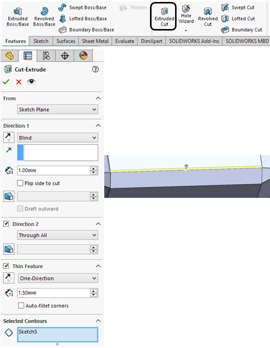
STEP 11.
Create a cut in the main body by extruding the previous sketch as Thin feature 1mm deep and on one-direction of 3mm upwards
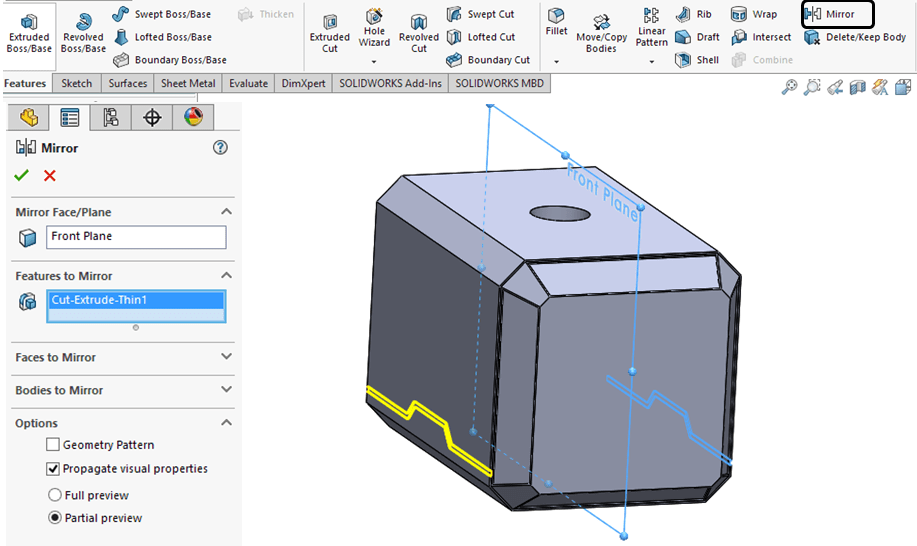
STEP 12.
Click the Mirror icon, select the Front plane as mirror plane and apply it to the previous cut extrude as shown:
STEP 13.
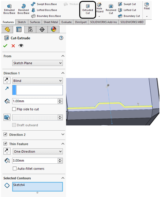
Select the top surface of the main body and sketch a line with 3mm distance from the edge:
STEP 14.
Do again a extruded cut as thin feature of 1mm deep and 1.5mm width upwards
STEP 15.
Create a new ref. Plane with an offset of 45mm from the Right plane as shown:
STEP 16.
On the new ref. plane sketck a profile coincident with the surfaces on the main body as shown
STEP 17.
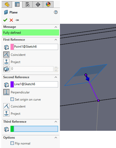
Create the 2nd ref. plane using the point and line as references from the previous sketch as shown;
STEP 18.
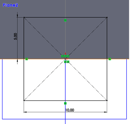
On the 2 ref. plane sketch a center rectangle as shown:
STEP 19.
In the Features toolbar click on Swept Cut icon and use the previous sketch as profile sketch and for path select the sketch created at STEP 16;

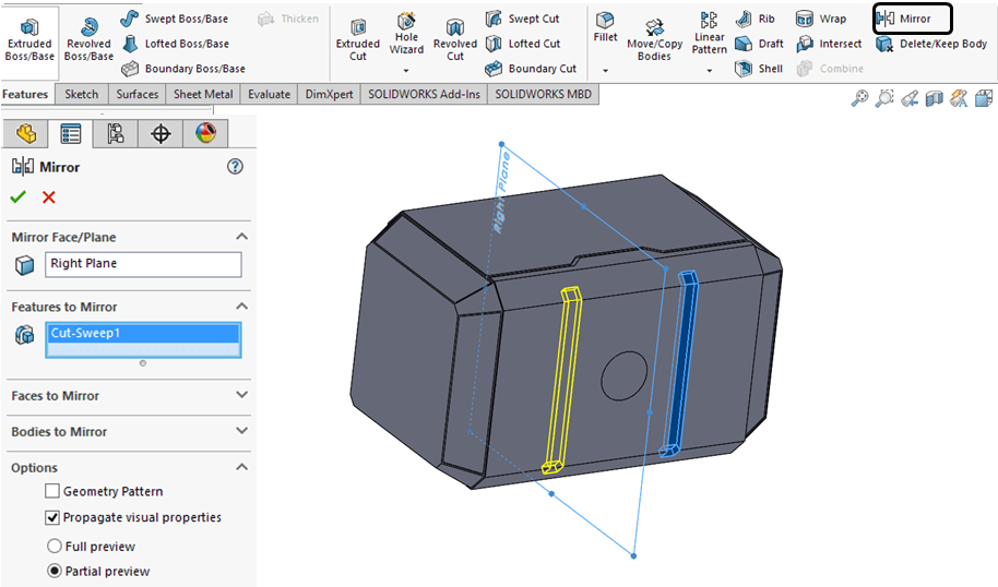
STEP 20.
Click on Mirror icon and select the right plane as mirror plane and apply it for the previous Cut-Sweep feature.
STEP 21.
The following engraving will be added on the drafted surfaces.
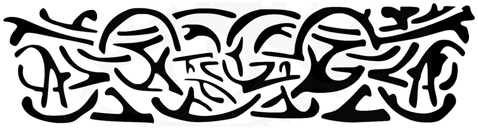
Before to create the feature on your SolidWorks part, you must fisrt convert this image to a SolidWorks compatible file. Usually from PNG file format to dxf file format.
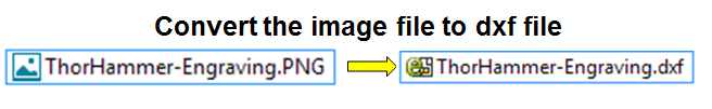
To do the image conversion you need a dedicated software on this purropse. There is also the posibility to do this for free directly online (just google the text “png to dxf converter” and you can try the options provided), you can also buy such a software for more advanced editing options or you can download and instal on your PC , a dedicated freeware for basic conversions from image files to dxf.
Me personally I love INKSCAPE sofware. It is very good for dxf conversions, its free verision has already a lot of advanced editing options and the the conversion results are exelent. I recommend it.

STEP 22.
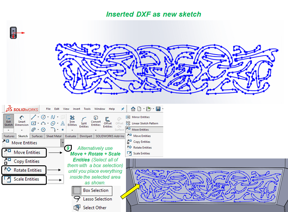
Once you’ve converted the engraving image to a dxf file, you can return to your SolidWorks file and continue to work on your part. To add the engraving on the drafted surface, first you must select the surface where you want to put the engraving, then from the Insert Menu click on DXF/DWG… option and follow the steps as follows:
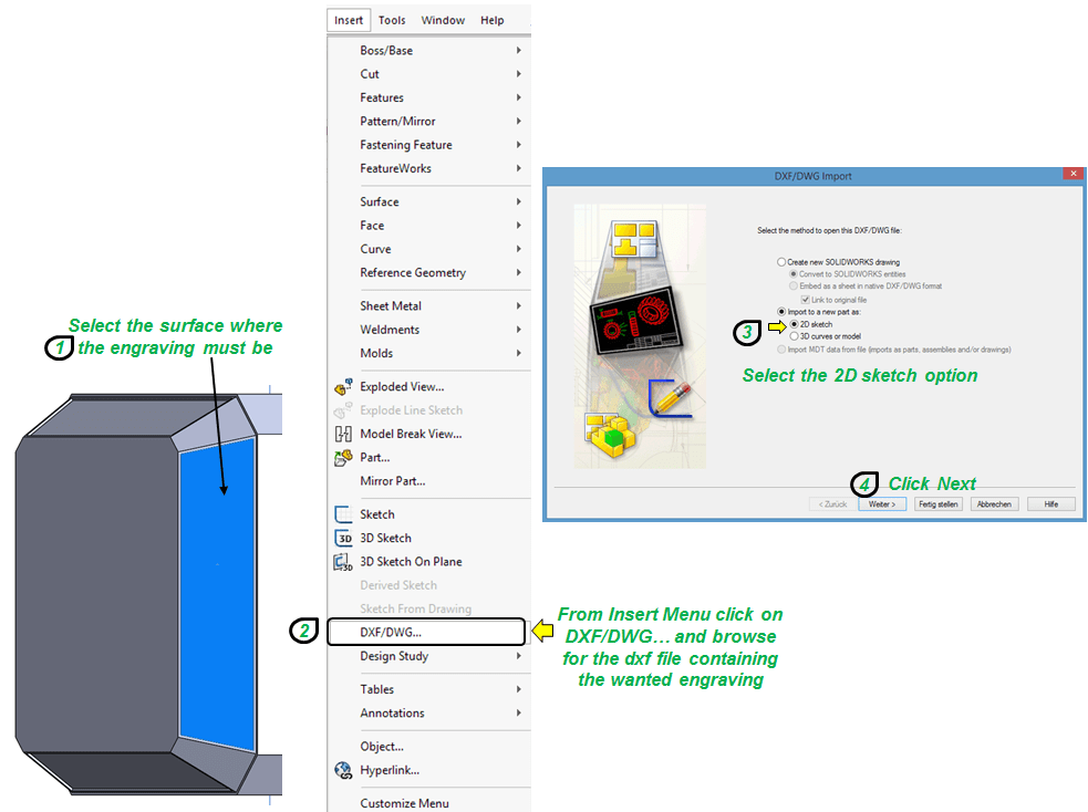

Once the DXF is imported in Solidworks as sketch on the selected surface, it will be places freely as shown. You must used the options provided by SolidWorks to Move, rotate and scale the entire sketch until it will fit inside the area where you what to put it.
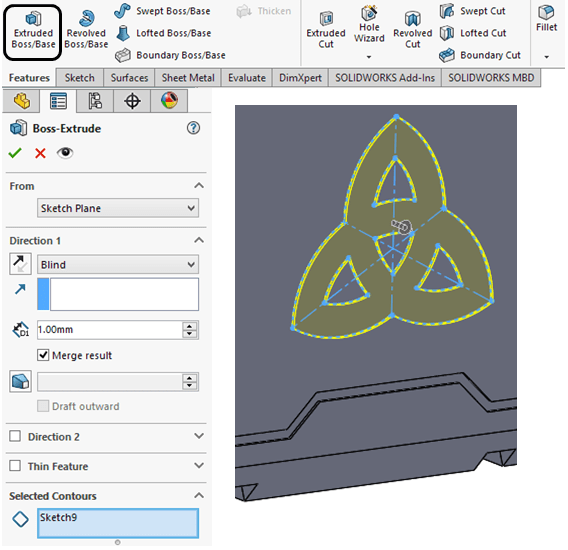
STEP. 23.
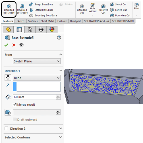
When the sketch is placed accordingly click on Extruded Boss/Base icon and extrude everything at 1mm.
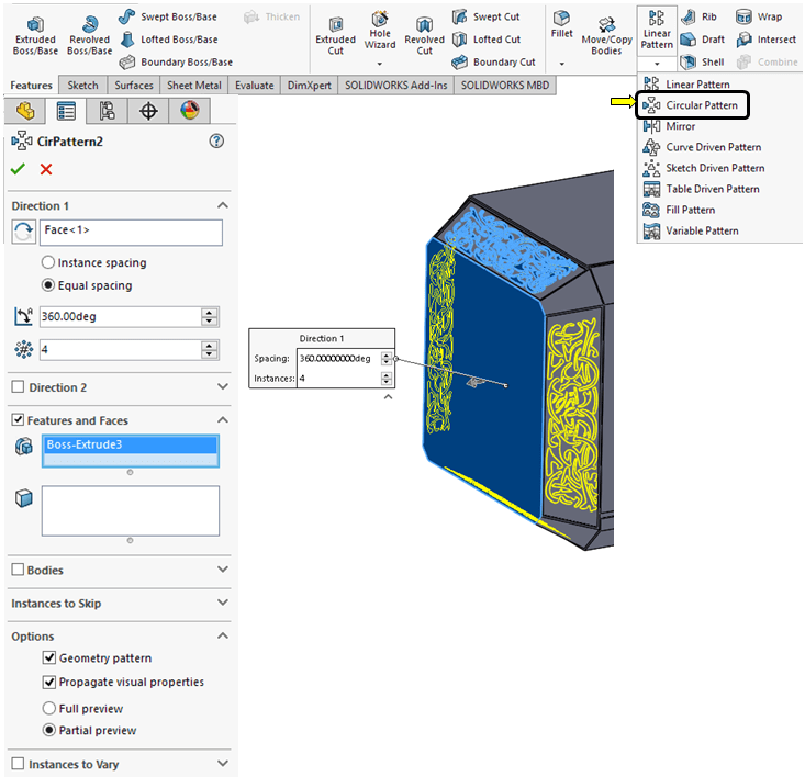
STEP 24.
Next, apply a circular pattern on each drafted surface as shown.
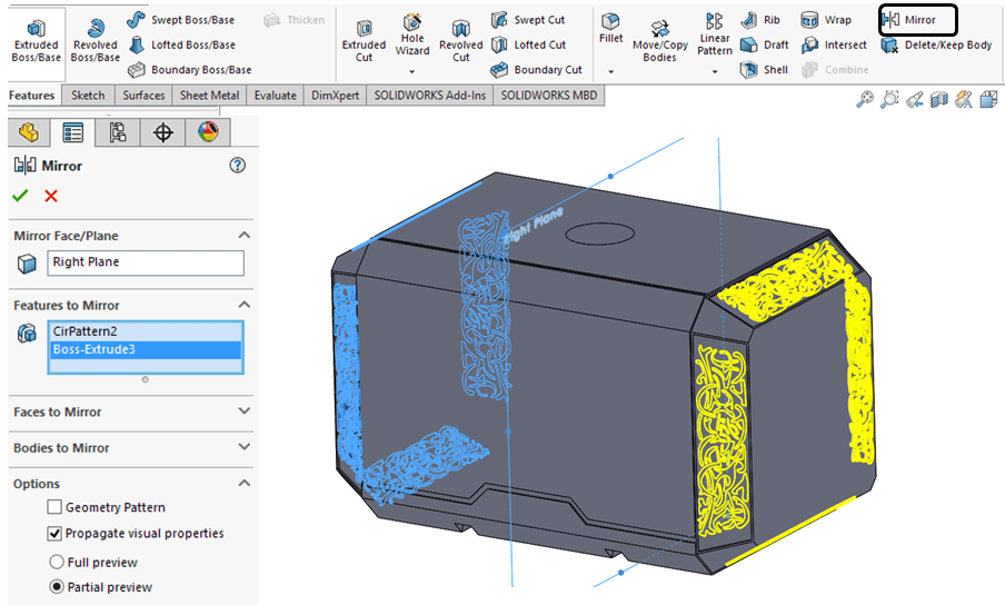
STEP 25.
Click on Mirror icon and select the Right plane as mirror plane and apply the same extruded engraving on the other side.
STEP 26.
Select the sidewise surface and create the sketch as shown:
After trimming the entities, in case you don’t get the same result and your sketch is overconstrained, delete the geometrical constraints one by one until your sketch in no longer overconstrained and ready to be used.
STEP 27.
Click on Extruded Boss/Base and extrude the sketch with 1mm as shown.
STEP 28.
Select the surface of the extruded profile and draw the sketch as follows:
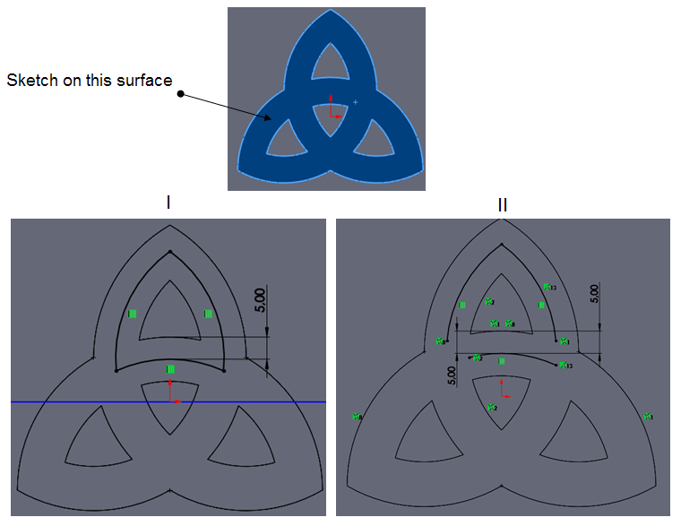
STEP 29.

Click on Extruded Cut icon and create a thin feature of 1mm deep and 1mm width on mid-plane as shown.
STEP 30.
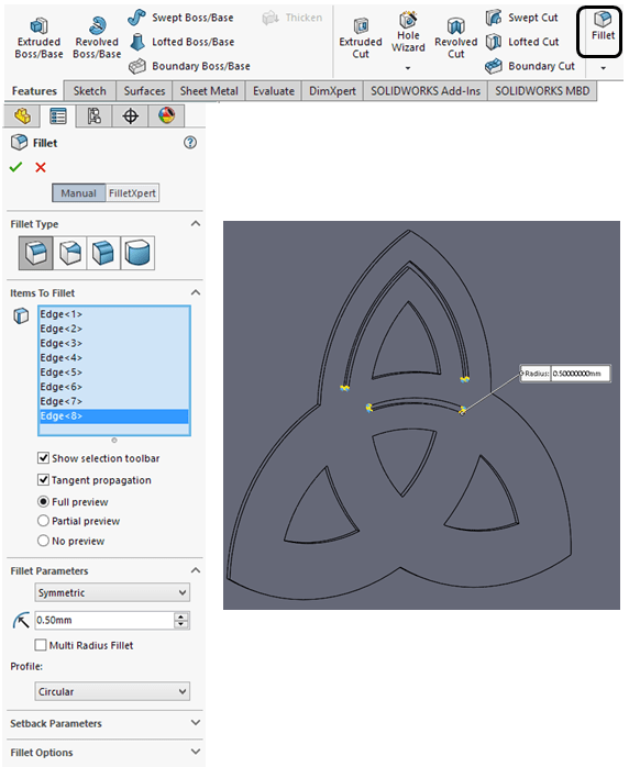
Apply 0,35mm filles as shown
STEP 31.
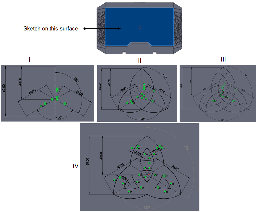
Click on the central surface as shown and create a sketch made of construction elements

STEP 32.
Using the same central surface and the mid-point created in the previous sketch, click on Axis icon to create a reference axis.

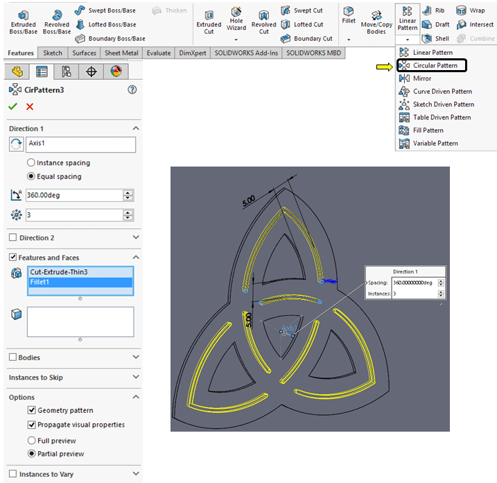
STEP 33.
Create a circular pattern of 3 entities around the previoulsy created axis as shown:
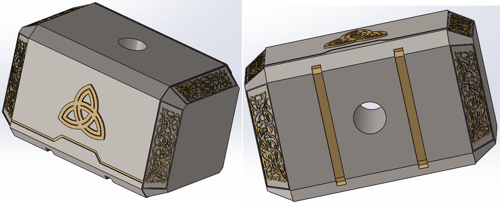
FINAL PART
Apply Appearances, for instance “Burnished Titanium” on the main body and put “Polished Gold” on engraved surfaces and cuts, the final part looks like this:
PART 7 – Helix
STEP 1.
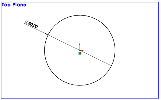
Create a sketch as circle on the Top plane:
STEP 2.
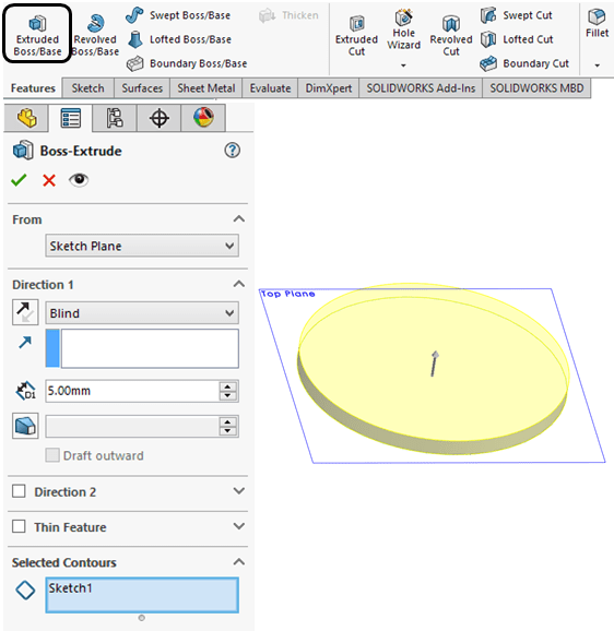
Extrudde the sketch with 5mm
STEP 3.
On the top surface create a sketch as shown:
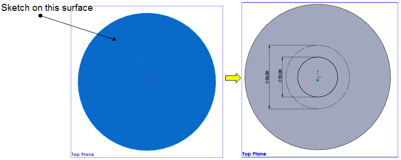
STEP 4.

Extrude the inner circle with 20mm
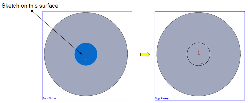
STEP 5.
Create a new sketch on the inner circular surface by converting the edges of the previous feature.
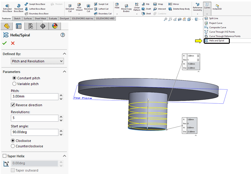
STEP 6.
Starting from the converted sketch click on Helix and Spiral icon and create a Spiral with the following parameters:
STEP 7.
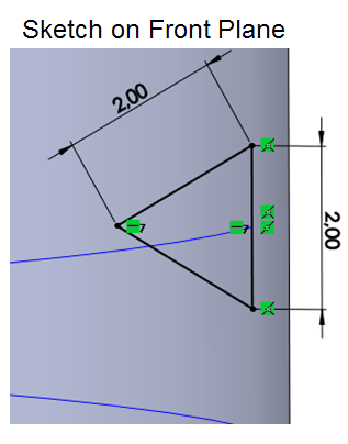
Click on the Front Plane and sketch a isosceles triangle of 2mm connected with the spiral as sweep profile, as shown:
STEP 8.
Sweep the prefious sketch on the spiral path as shown:
FINAL PART
Apply Appearances, for instance “Satin Finished Gold” and the final part looks like this:
THOR HAMMER Assemby
To create the final product,all the previously created parts will be joined in one assembly file.
STEP 1.
Create new Assebly

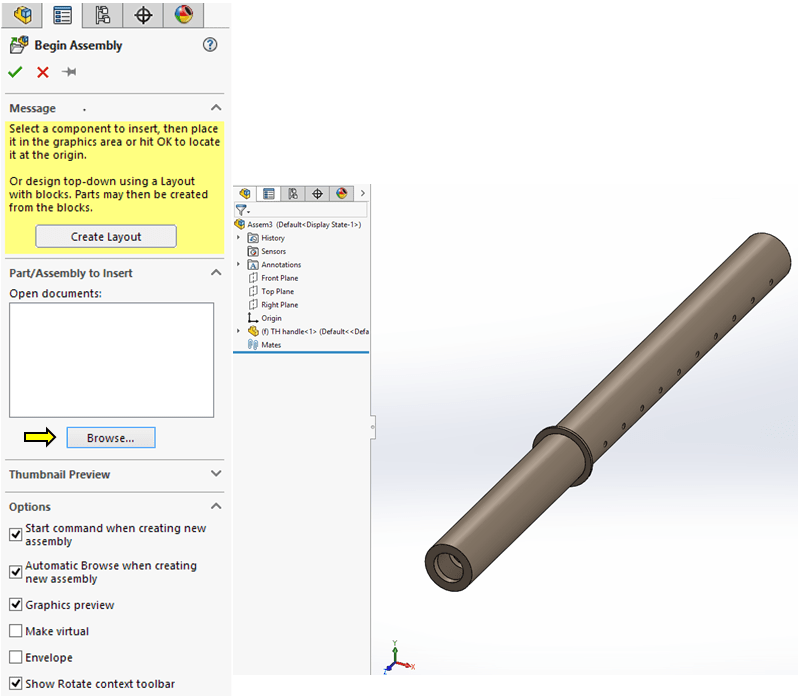
STEP 2.
By default, when a new assembly file is created, Solidworks is asking you to Create the layout and the Begin the Assebly dialog window is already asking for the first part to be inserted. So, click on Browse… button and from your working folder pick the Handle file and once visible on the screen, click again on it to close the “Begin Assembly” dialog window.
STEP 3.
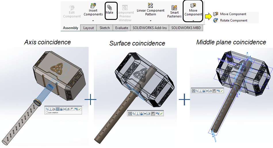
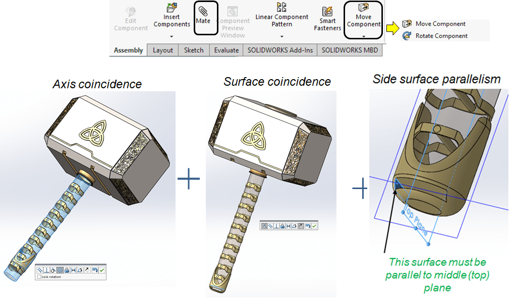
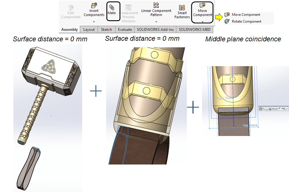
Click on Insert Components icon and add the second part. Then by clicking the Mate icon you can add further constrains to the new part in the assembly.
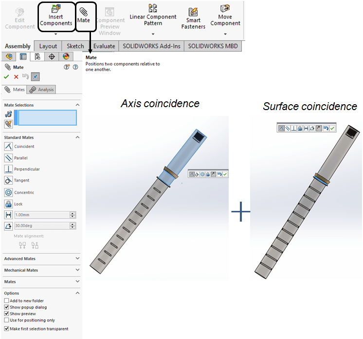
STEP 4.
Continue to add parts as described. If necessary you can also use the options under “Move Component” icon to roughtly place your part in the assembly before to add the final constraints.
STEP 5.
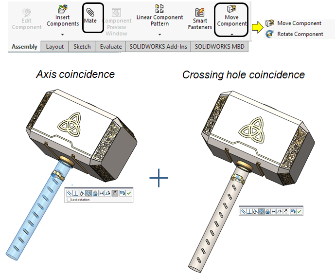
Add the helix part in the same way;
STEP 6.
Add the Handle ring
STEP 7.
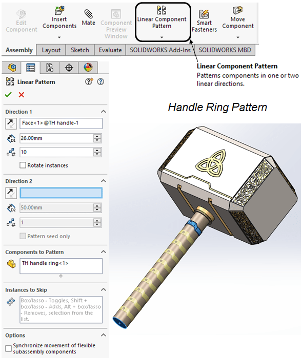
Pattern the handle ring
STEP 8.
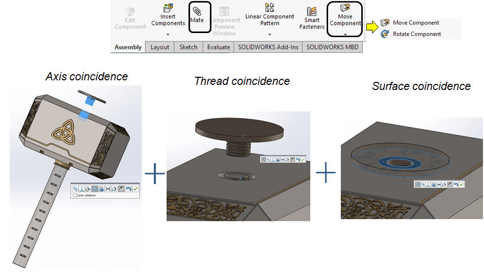
Add and constrain the Bottom cap
STEP 9.
Add and constrain the rubber band.
FINAL PRODUCT
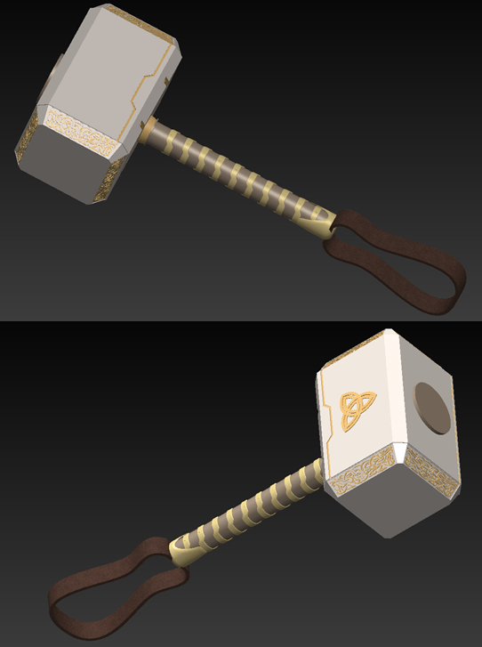
This work is also available as video version on my YouTube Channel as embedded below:

Leave a comment