
Generative Shape Design Workbench is an interactive environment and it works perfectly in combination with Part Design Workbench. Therefore to explore a bit more in details how does GDS works, let´s create a part which is only possible with GSD, such as a Bike Saddle.
The most easier workbench to work with in any CAD is in Part Design because features are created quite fast using simple sketches which are then extruded in a direction to generate a 3D object. But in most cases the objects we want to create are not always made only form regular shapes, they are very much based on irregular shapes. For that reason the Generative Shape Design Workbench is together with Part Design the essential environment to create any type of object you want.
Let´s begin the Bike Saddle design.
STEP 1.
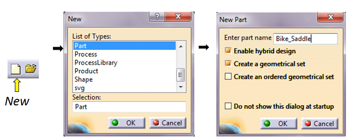
Create a new part.
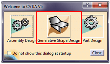
Activate the GDS workbench.
STEP 2.
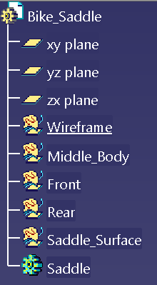
Before to start drawing it is always good to organize your work in a well defined structure. Therefore add the necessary Geometrical Set in the SpecTree as shown.
STEP. 3
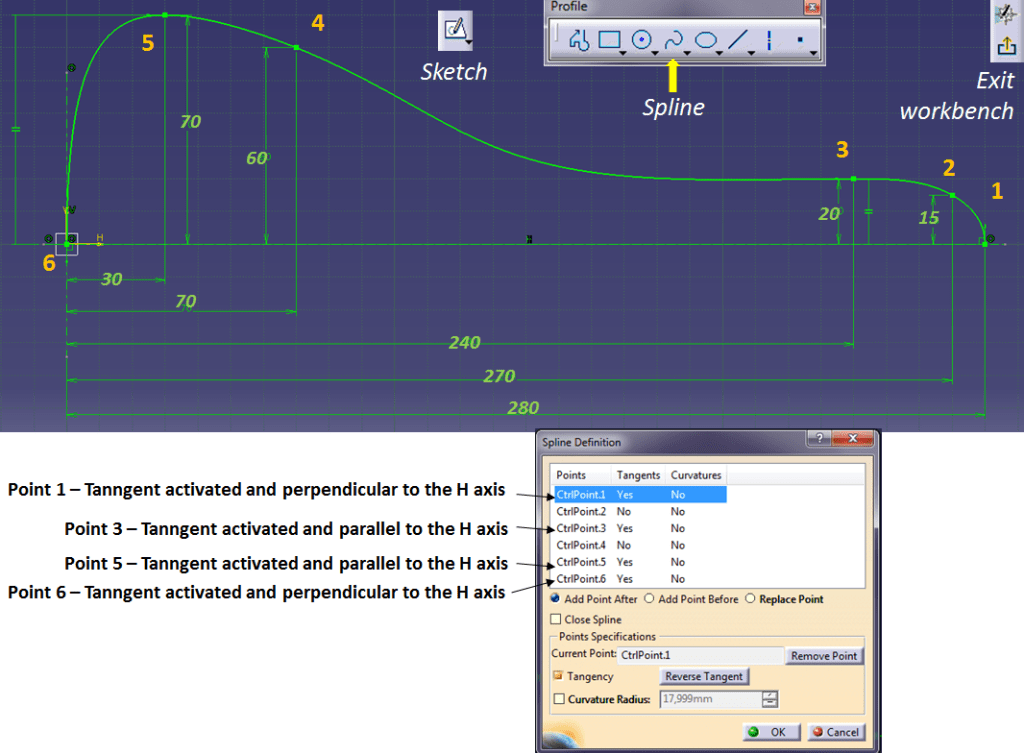
Obviously the first feature to be created is the reference sketch on which the rest of design work will be added. So click on Sketch Icon —>Select the sketching plane (for instance XY plane)–> In the Profile toolbar click on Spline icon and draw a spline in 6 points.
Draw the spline from right to left, activate the tangency for points 1, 3, 5 and 6 and make it fully constrained as shown below:
STEP 4.
ADVICE: The result found should be similar to the dimensioned sketch. The strak curve is a polynomial of degree 5 and is only fixed once its points positions, its tangents and curvatures have been defined. Since some of these parameters are still free, differences can occur. Especially when points that are close together causing a strong curvature, a subsequent smooth area swings out. Therefore, if further constraints are inserted, then it is possible to optimize the spline in the direction of a balanced, slightly changing curvature. In such a case, it is advisable to: define the curvature at point 1 more precisely with curvature continuity, to optimize the position of point 2 in the creation sequence or to insert an additional tangent in point 3 with a small angle in the direction of width.
In order to get a usable surface result, the curves should run as smooth as possible. To evaluate the curve quality, in the Analysis toolbar click on “Porcupine Curvature Analysis” icon and choose the type “Curvature” to see how well your curve behaves. The displayed curvature continuity in form of spikes in radius – or curvature length (1/R) should be as uniform as possible. Unnecessary changes in the algebraic sign (+ or -) of the curvature indicate a wavy course of curve with turning points.Not so much as the absolute value, but rather the relative course of curvature is informative, good enough to see if there is a problem with your curve or not. If you want a more detailed analysis, in the Porcupine Curvature dialog box click on “More…” option to expand the dialog box and work with the displayed parameters. (I will explain all the functions in the Analysis toolbar more in detail in another post, but for now I just show you that you can use this very helpful function when you create curves to be used in surface design).

Once you´re clear with the curvature analysis, if you click OK in the dialog box, the analysis is saved in the SpecTree and you can review it anytime later or you can simply delete it.
STEP 5.
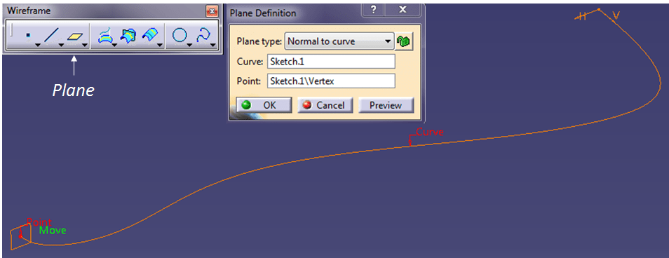
In GSD Workbench click on “Plane” Icon to create a new plane normal to curve at the front point as shown below. This is from now on, the symmetry plane to be used for designing the rest of the part. (You can rename it in the SpecTree you can rename this plane as “Symmetry_Plane”.
STEP 6.
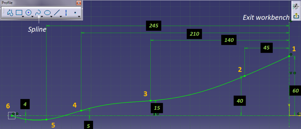
In the symmetry plane create a new sketch, as a spline in 6 points. Put the necessary constraints to have a fully defined sketch (as shown below) and click on Exit workbench icon to return to GSD workbench.
STEP 7.
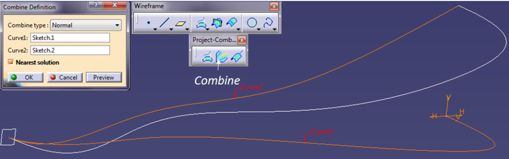
The combination between the 2 previously created sketches will result in the final sidewise profile of the bike saddle. So in the wireframe toolbar, click on “Combine” icon and select the 2 sketches as Curve 1 and Cruve2, keep the “Nearest solution” option active and click OK.
STEP 8.
Using again the symmetry plane create a sketch to define the height of the bike saddle. In the Profile toolbar click on “Spline” icon and starting from right to left draw a spline in 6 points. Make the end points coincident with the corresponding endpoints from the previous sketch, put all the other necessary dimensions to have a fully constrained sketch and then Exit the workbench in order to return to GSD environment.

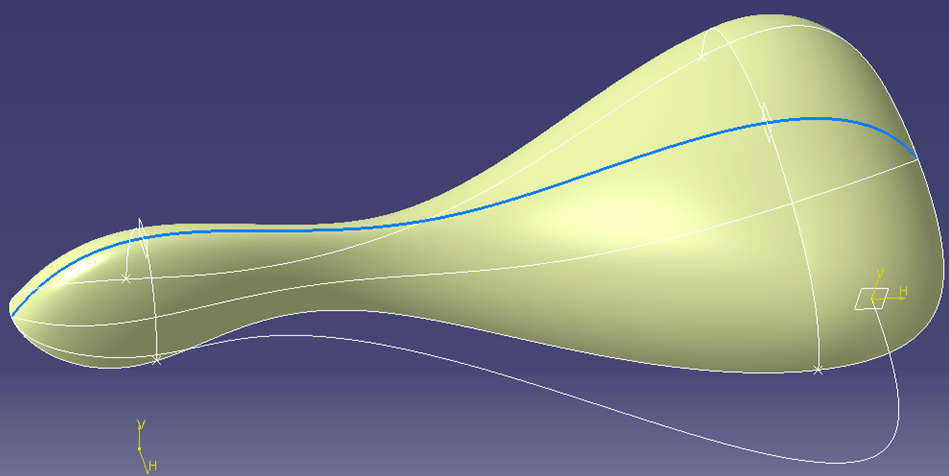
Once back to GSD workbench, change the curve color for instance make it blue.
STEP 9.
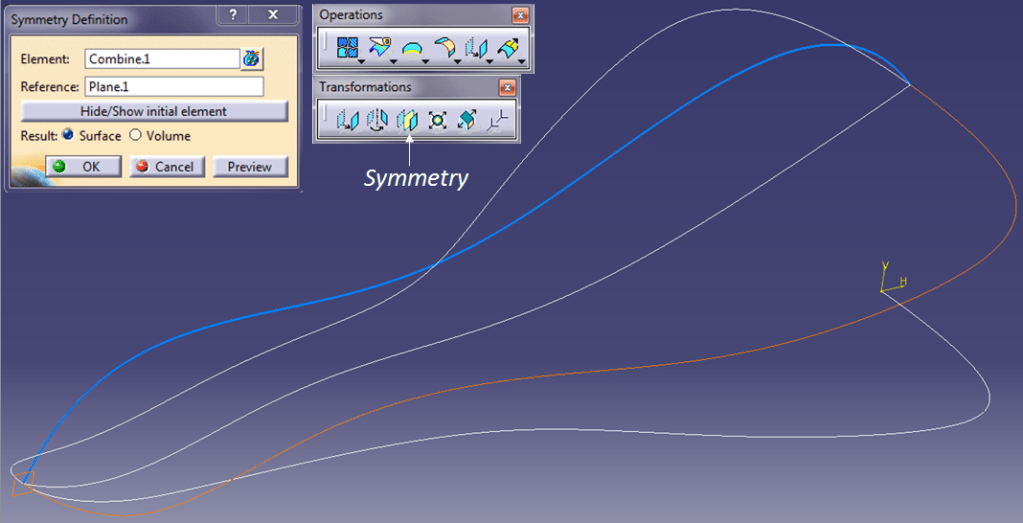
Create the left sidewise profile by making the symmetry of the right side. In Operations toolbar, click on “Symmetry” icon, select the sidewise profile as Element to be symmetrical, choose the symmetry plane as reference and click O.K.
STEP 10.
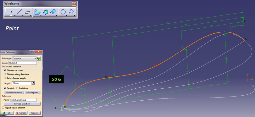
On the middle (blue) curve create 2 points. One at 50mm and the other at 250mm geodesic distance from the endpoint in front side.
STEP 11.
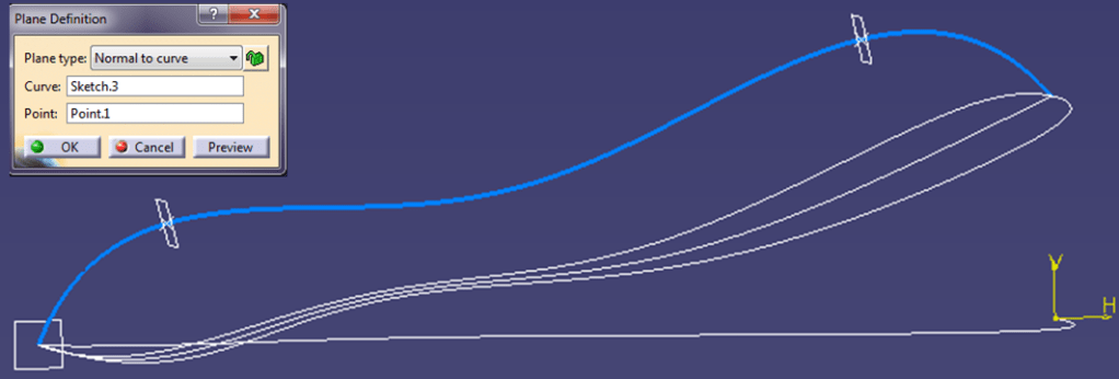
On each of the 2 previously created point, create a plane normal to middle curve.
STEP 12.
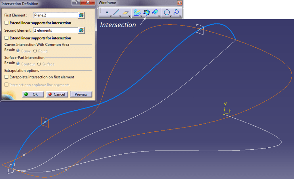
With the 2 previously created planes create the intersection points with the sidewise profiles left and right.In the Wireframe toolbar,click on Intersection icon and select the front plane as First Element and the 2 profiles as Second Element. Do that with the rear plane too.
STEP 13.
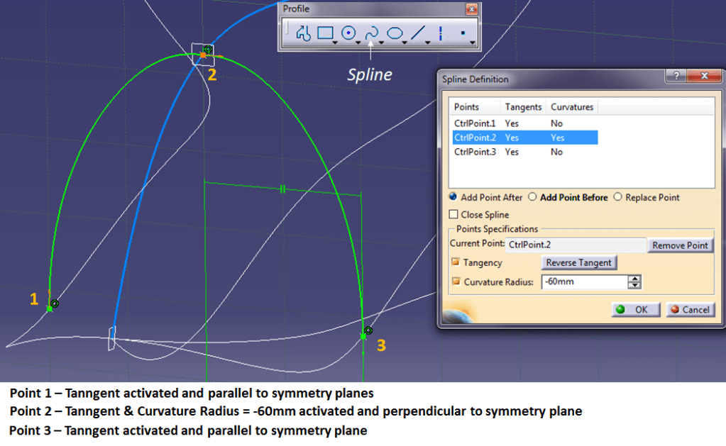
On the Front plane create a sketch using the Spline icon. Draw a spline in 3 points from left to right, activate the tangency for all 3 points and for the point 2 activate also the curvature Radius value at = -60mm. Make both endpoints of the Spline coincident with the intersection points on the reference curves (sidewise and middle curves).
STEP 14.
Repeat the Step 13 for the rear side. The only difference here is the Curvature Radius activated on point 2 with a value = -70mm.
STEP 15.
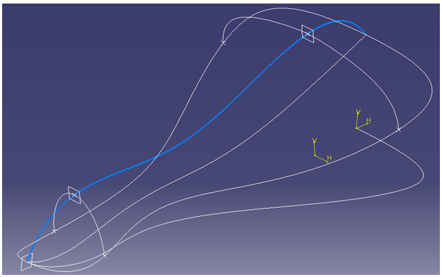
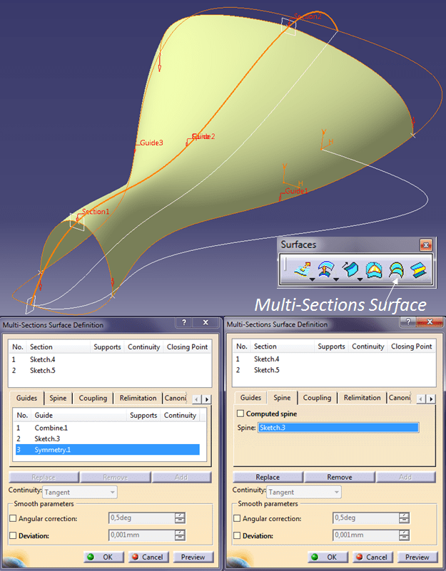
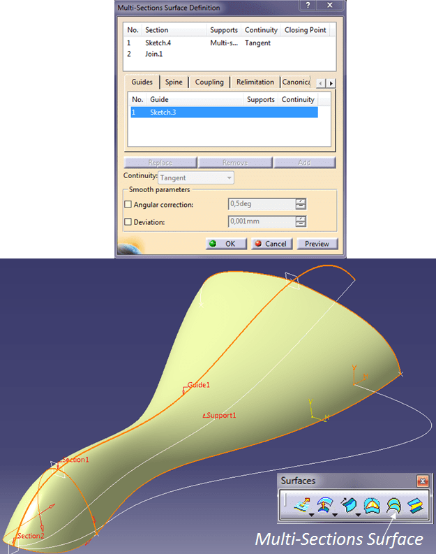
Now, in the SpecTree make the Middle_Body geometrical set active and create the middle surface using the “Multi-Section Surface” function from the Surfaces toolbar. Select the Front and Rear sketches as Sections and for guides use the 2 sidewise profiles and the middle blue curve. Use the Middle curve also as spline and click OK.
STEP 16.
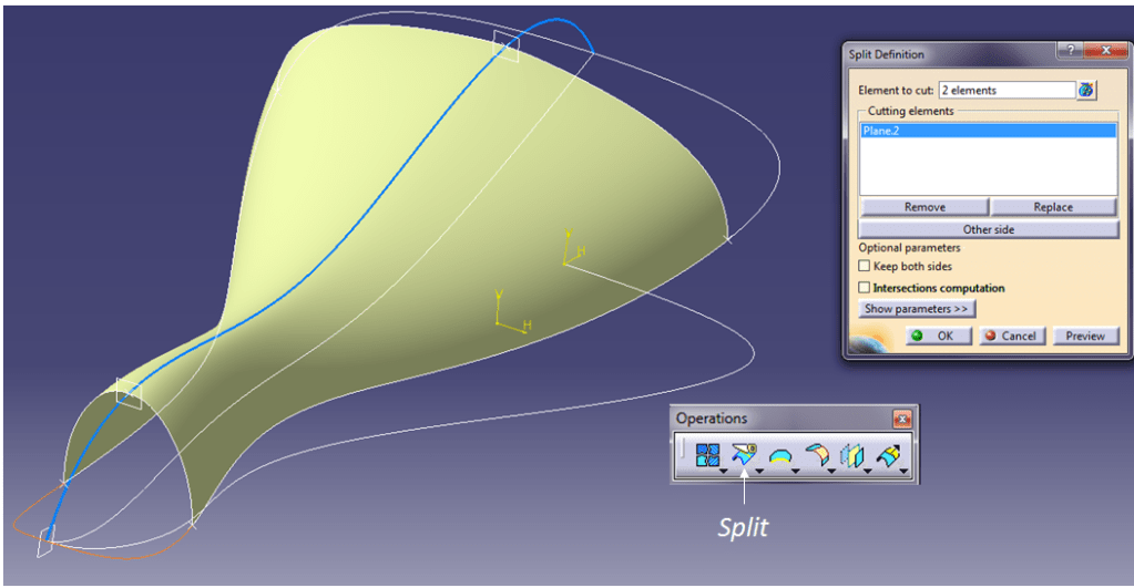
Continue with the surface in the front area. In Operations toolbar, click on “Split” icon and use the 2 sidewise profiles as Element to cut and for cutting element take the front plane and click OK.
STEP 17.
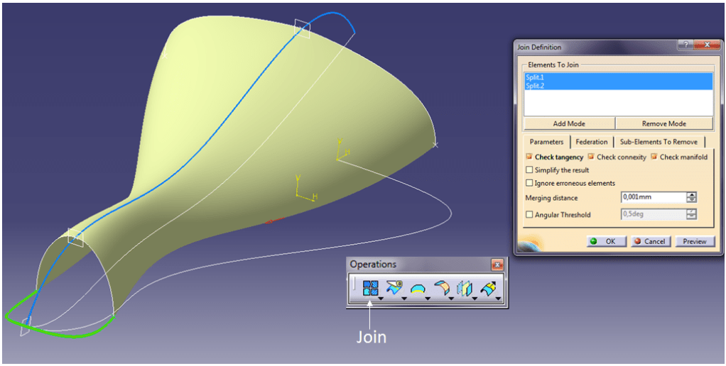
Join the 2 resulted curves from previous step in a single curve, keep all the checking options active and click OK.
STEP 18.
Create the front surface. In the Surfaces toolbar,, click on the “Multi-Section Surface” icon, select the Join curve from Step 17 and the front sketch with its support for tangent continuity linked to Middle surface as Section and use the middle blue line as Guide, then click OK.
In case the surface is not successfully created, check the direction of the red arrows for one or both sections, if necessary click on one of these red arrows to reverse its direction and click OK and the surface must be successfully created.
STEP 19.
Repeat the Step 18 for the surface on rear side.
Now all the necessary surfaces are created.
STEP 20.
To finish the saddle design and add thickness to the part, all surfaces must be joined in a single surface. In GSD workbench click on “Join” icon from Operations toolbar. Select all surfaces, keep the checking option active and click OK.

The Saddle surface is now ready and thickness can be added.
STEP 21.
Switch on the Part Design workbench and on Surface-Based Features click on “Thick Surface” icon. Insert a 2mm value for the First Offset and click OK.
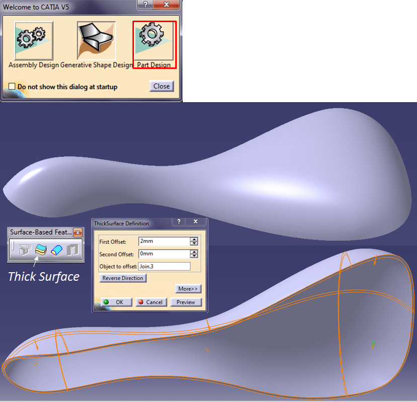
In this way the Saddle design is created.
STEP 22.
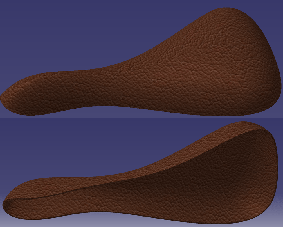
You can now customize the design by adding material and make your part more attractive. Therefore, click on “Apply Material” icon, make sure the PartBody named Saddle is in work object in SpecTree and from materials library choose for instance the Brown Leather, then click OK.

Material is added, change the view mode in “Shading with Material” and here is how the part looks like:
This exercise is also available as video version on my YouTube Channel.

Leave a comment