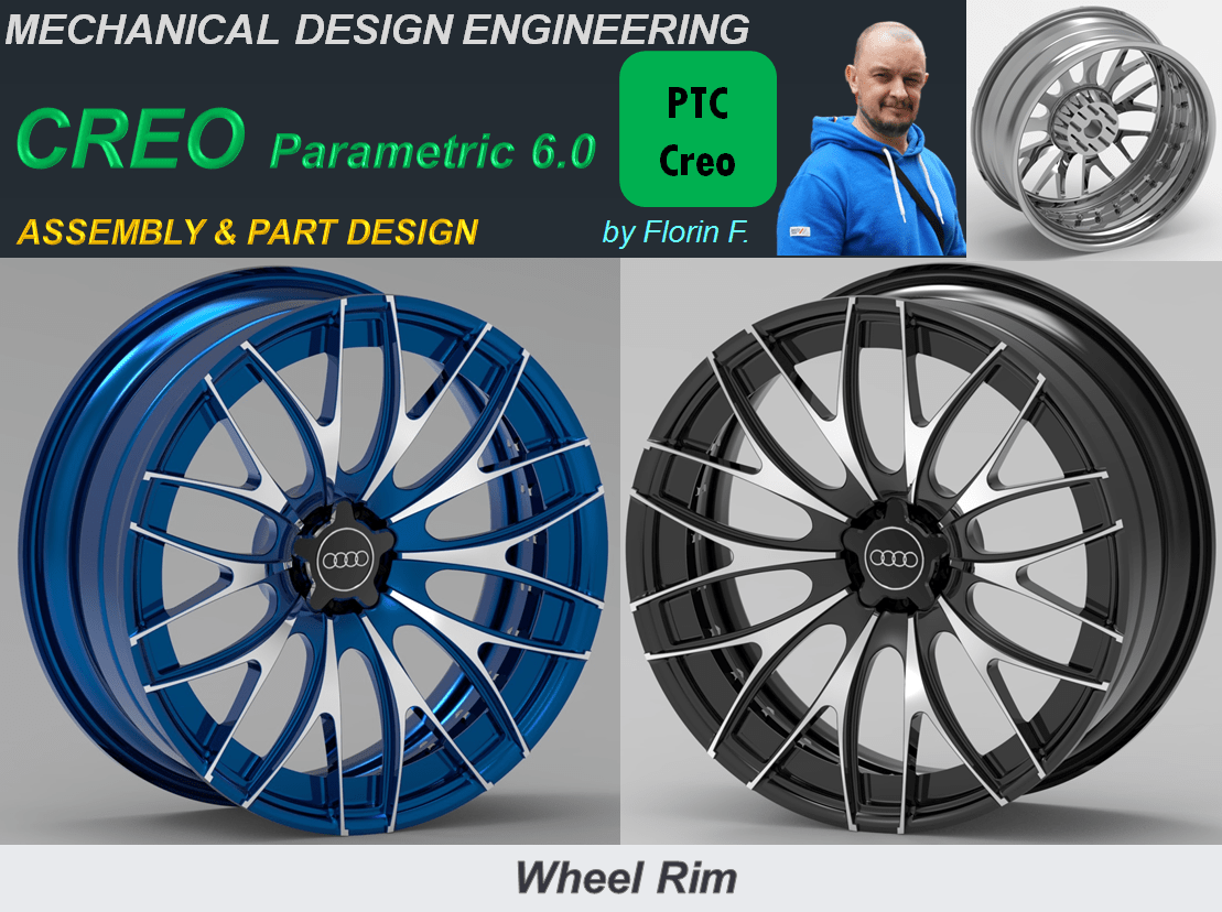
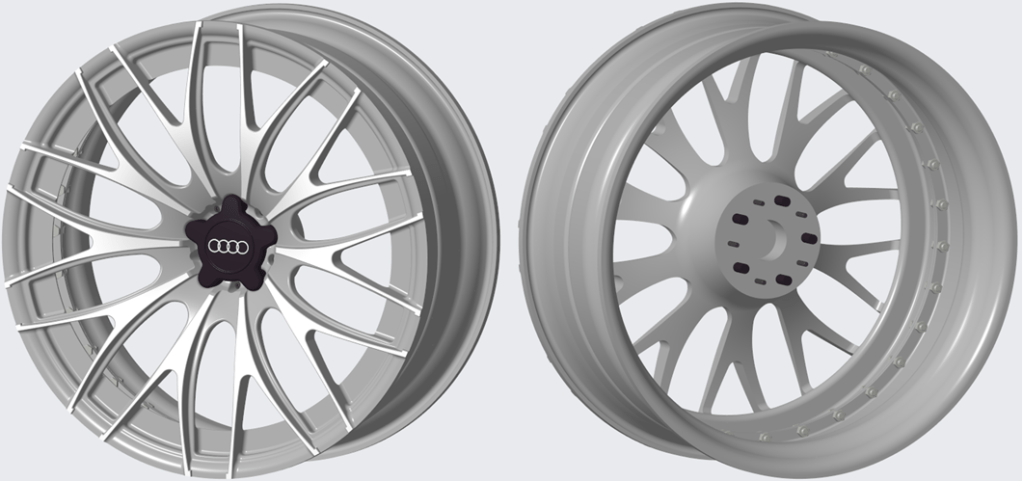
A wheel rim design can be done in different ways, depending on the wanted pattern and the used CAD software. In this example I show you a version of Wheel Rim used on AUDI cars and how to do it in CREO Parametric CAD software. A wheel rim can also be done in 1 piece but the one I will show you next it’s done in 3 main bodies: The Front Rim, The Rear Rim and the Audi Logo part.
Let’s start:
FRONT RIM
STEP 1.
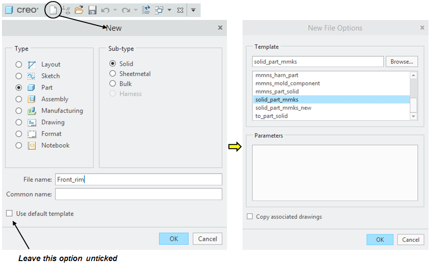
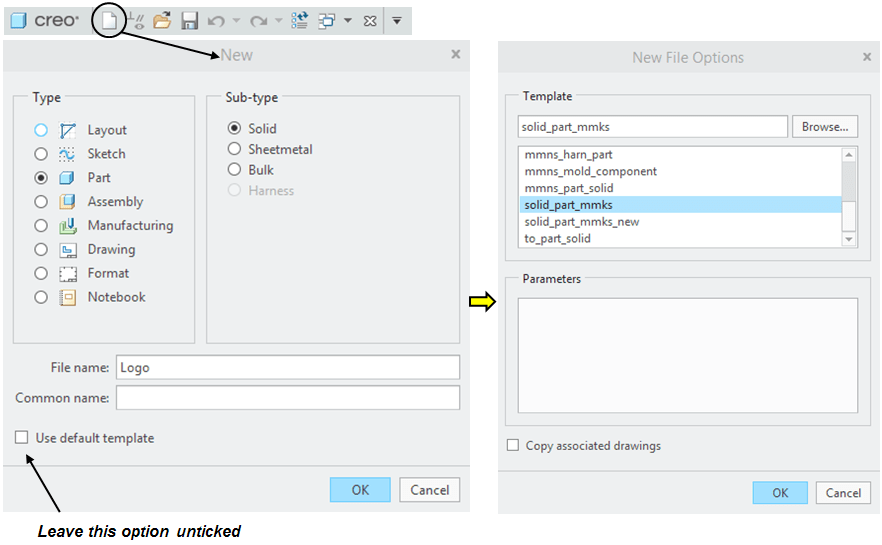
Create a new Part and rename it: Front_rim
STEP 2.
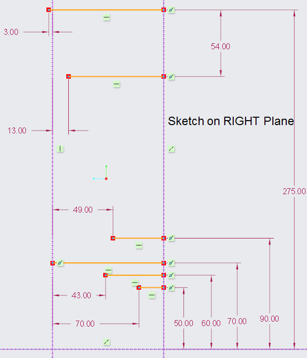
On RIGHT plane draw the horizontal lines as shown:
STEP 3.
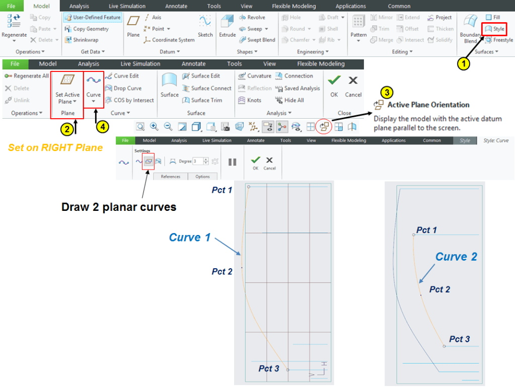
Click on Style icon to enter the Style Workbench and follow the steps to create 2 curves in 3 points (arrange both pct. 2 somewhere near the middle of the curve) as shown:
Without leaving the Style workbench and the active plane, click on “Curve Edit” icon and continue to adjust the curves at the end points and the middle point. The end points must be edited in the “Tangent” tab and the Middle point in “Point” tab with the coordinates as shown:

…. continue the editing for the 2nd curve as shown:

Then click OK to exit the Curve Edit Environment, and one more time click OK to exit the Style workbench.
STEP 4.
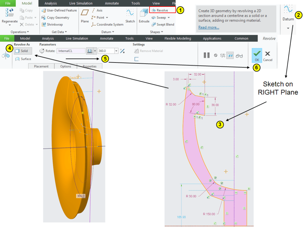
Back in Model Workbench, click on Revolve icon –> select the Right Plane for profile definition and draw the sketch as shown using the projections of the 2 previously created Style curves then revolve it completelly:
STEP 5.
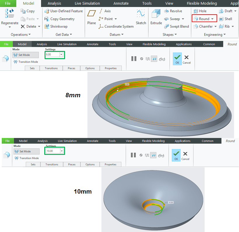
Add 2 rounds of 8mm and 10mm as shown:
STEP 6.

Click on Plane icon and create the DTM1 plane as offset of 105mm from Front plane.
STEP 7.
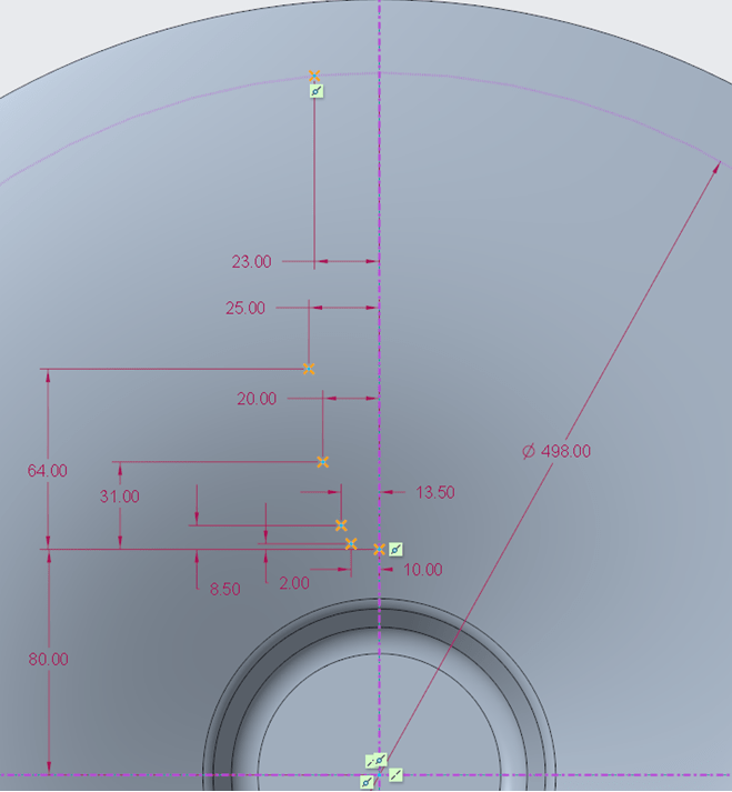
On DTM1 do a sketch with 6 points having the coordinates as shown:
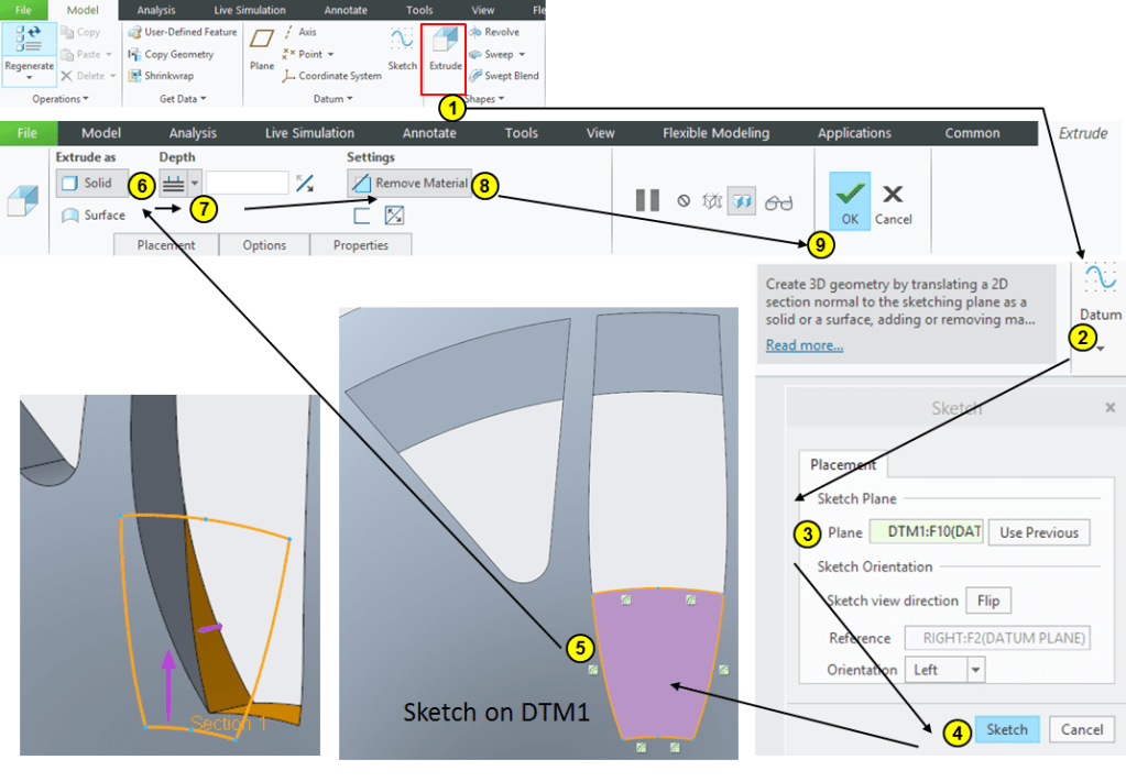
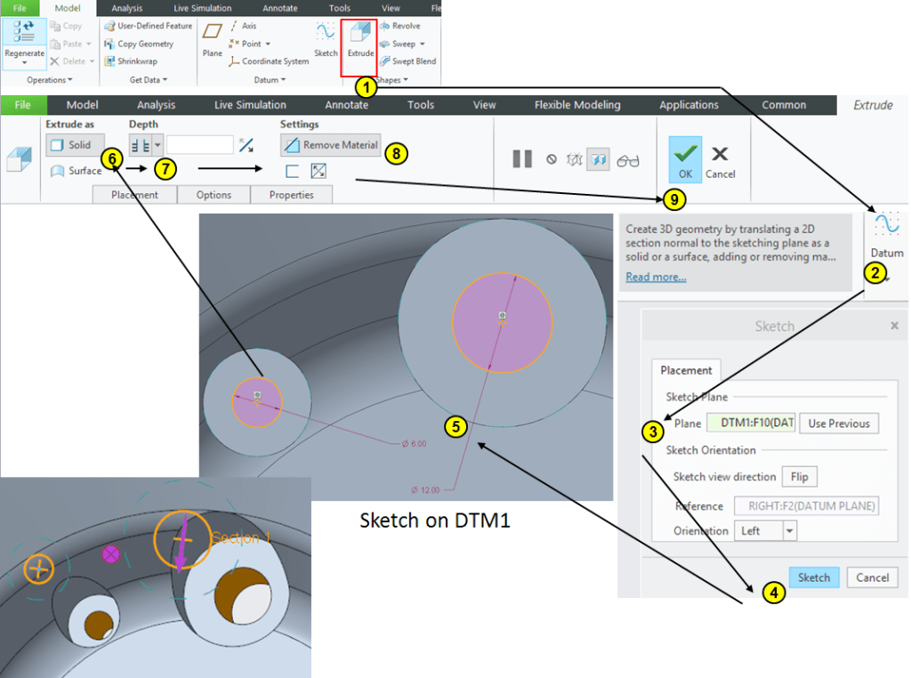
STEP 8.
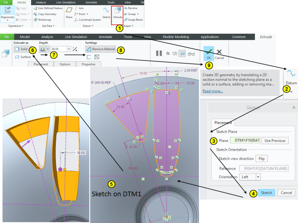
Click on Extrude icon –> select the DTM1 as sketching plane and draw the profiles as shown, the long profile being made by connecting the points from the previous sketch from STEP 7. Then Extrude everything at 38mm depth as removed material:
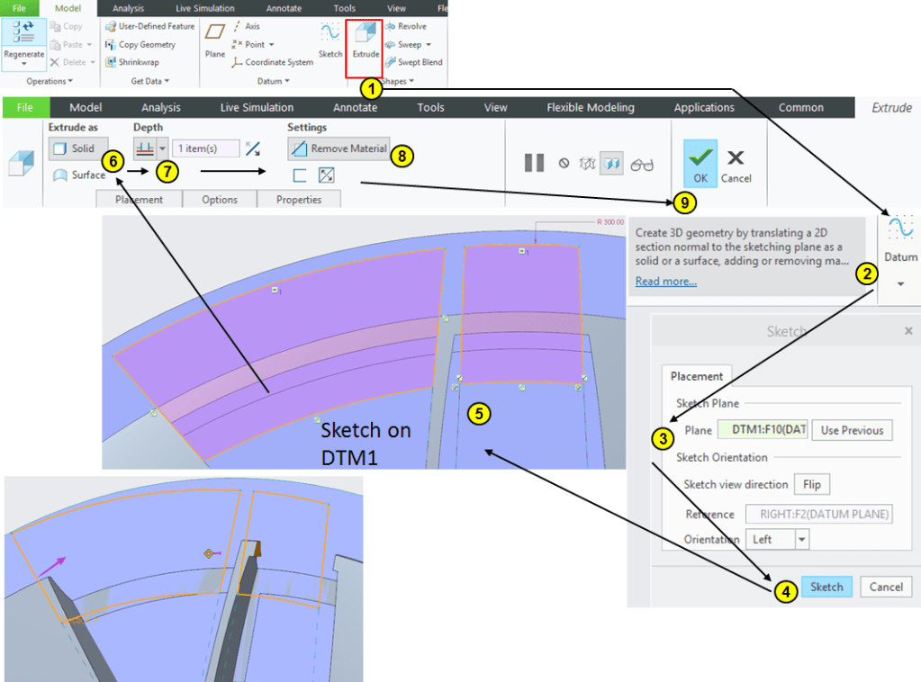
STEP 9.
Cut the unnecessary material from the long cut-out by projectiong the remaing edges from the previous cut, as 2nd extrude up to next surface:
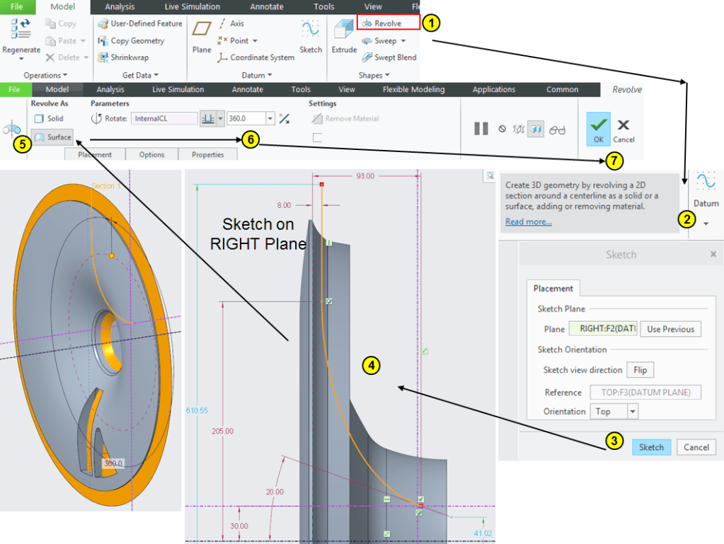
STEP 10.
Create a revolved surface based on the profile sketched on Right plane as shown:
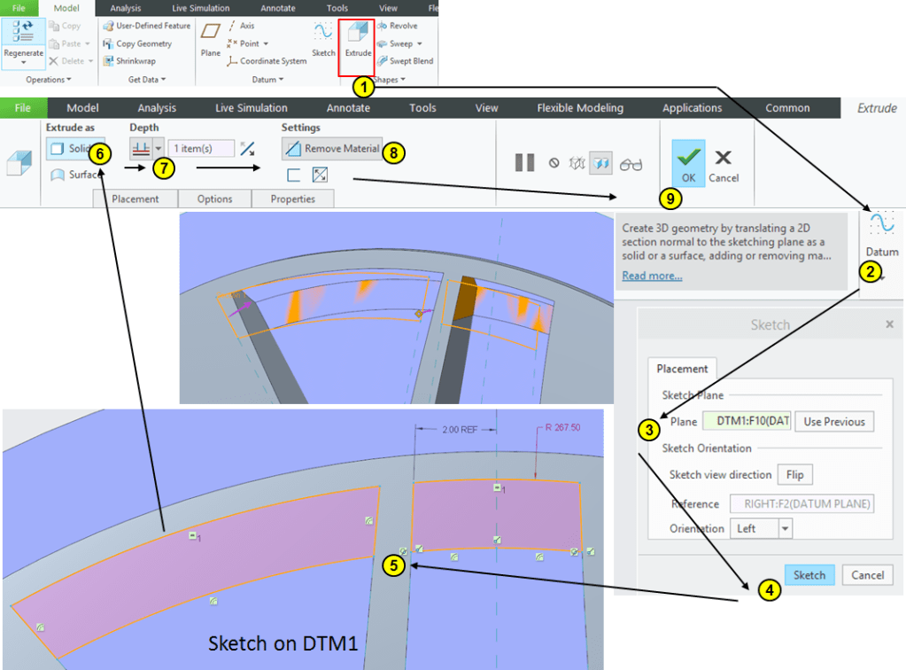
STEP 11.
Keep removing material by another Extrude made from a sketch on DTM1 using projections of internal edges and extrude it until the revolved surface as shown:
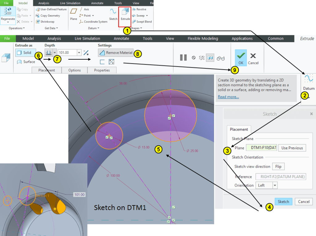
STEP 12.
Extrude 2 circles sketched on DTM1 at 101mm depth as shown:
STEP 13.
Create 2 circles concentric with the previous ones and extrude them through all as shown:
STEP 14.
Create a cut-out sketched on DTM 1 and extrude it up to the revolved surface created at STEP 10.

STEP 15.
Create the cut-out on outer area using edge projections sketched on DTM1 and extruded up to revolved surface from Step 10.
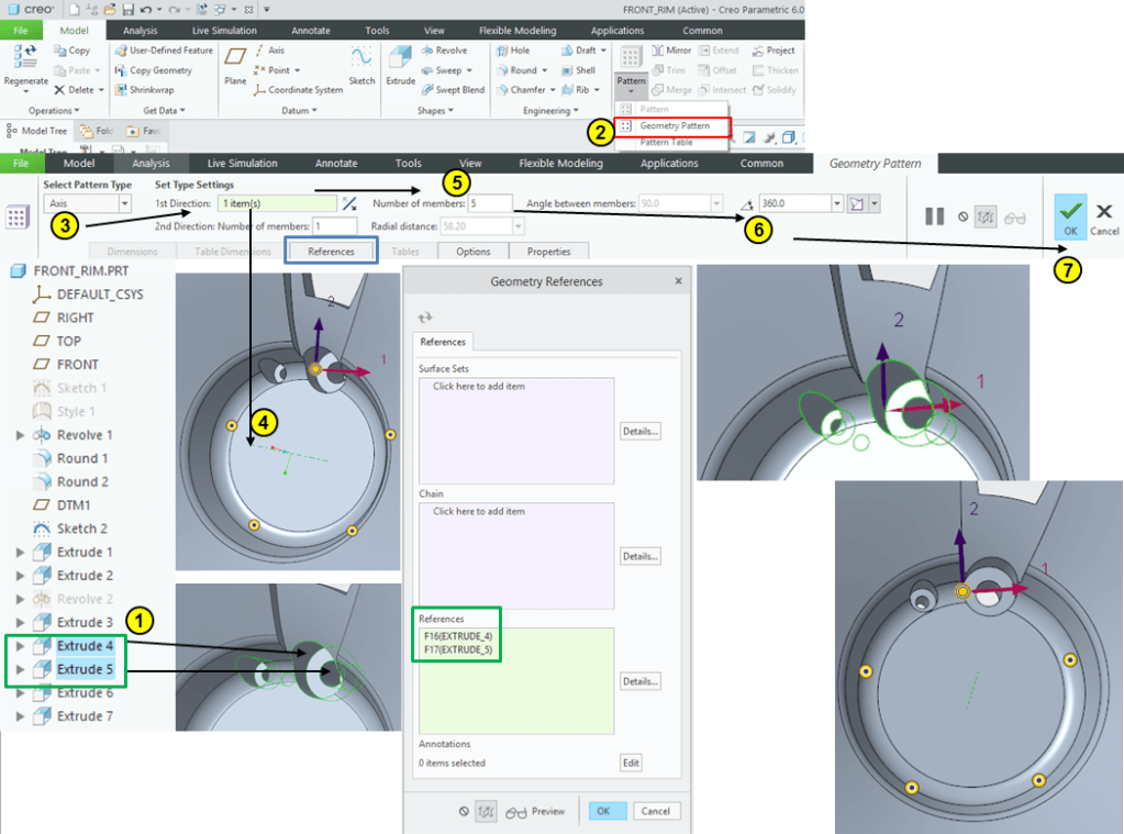
STEP 16.
In the model tree select the Extrude 4 and Extrude 5 and click on “Geometry Pattern” icon, then enter the parameters for Geometry Parttern as show (apply 5 instances):
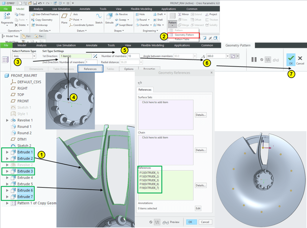
STEP 17.
In the Model tree select the Extrude 1, Extrude 2, Extrude 3, Extrude 6 and Extrude 7 and click on the “Geometry pattern” icon, then enter the parameters for Geometry pattern (for 10 instances) as shown:
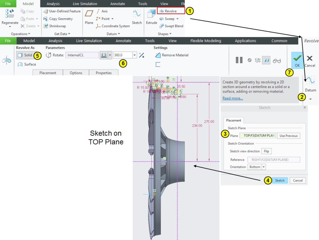
STEP 18.
Click on “Revolve” icon, select the TOP plane as sketching plane and draw the profile as shown:


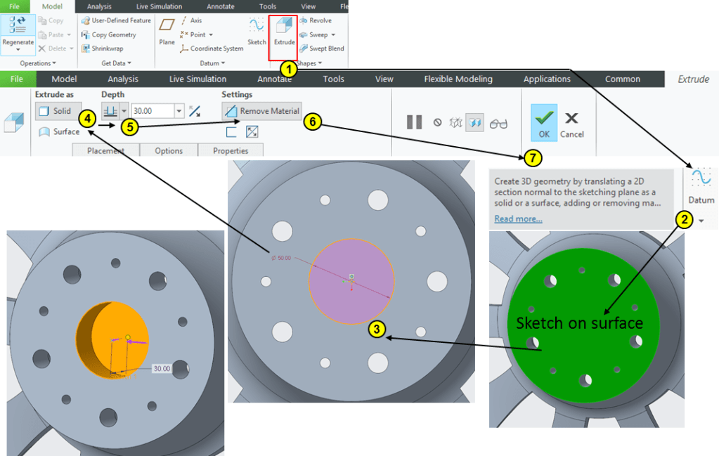
STEP 19.
Click on Extrude icon and select the backside of the inner shaft, then draw a circle of Ø50mm and extrude it 30mm as removed material, as shown:
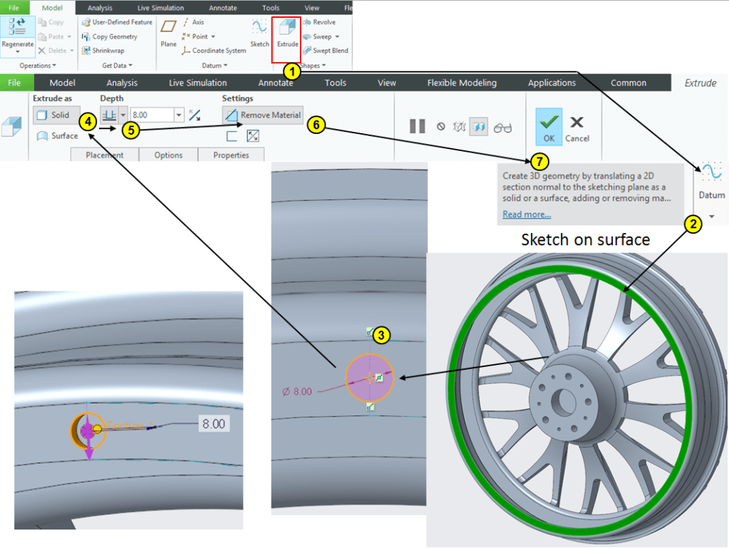
STEP 20.
Click on Extrude icon and select the surface on the rim’s backside. Draw a cirlce of Ø8mm and extrude it at 8mm depth:
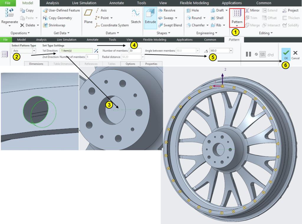
STEP 21.
Keep the previous Extrude feature (Hole) selected in the Model Tree and click on “Patern” icon then enter the Pattern parameters for 30 instances:
STEP 22.
Create Rounds as follows:
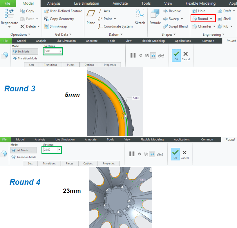
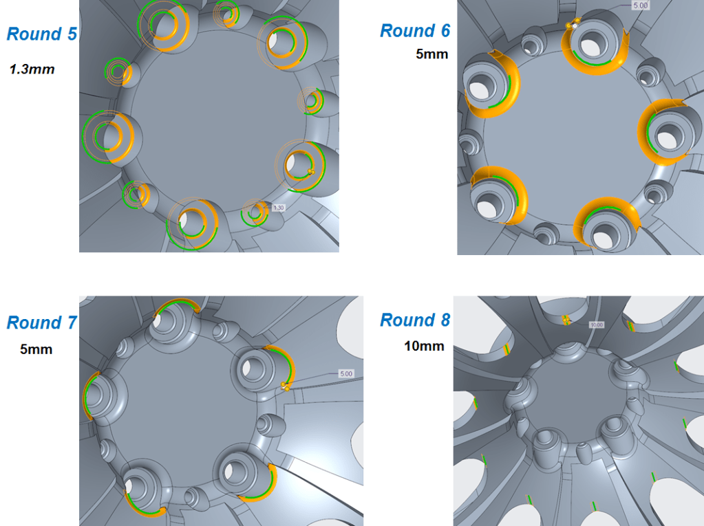
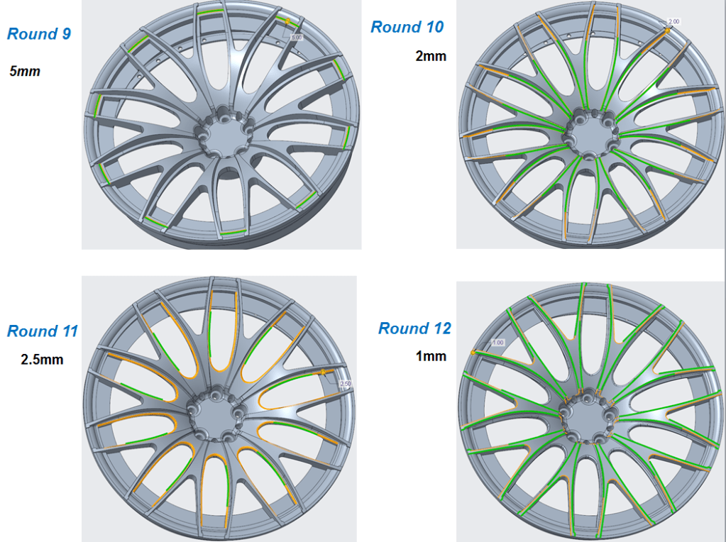
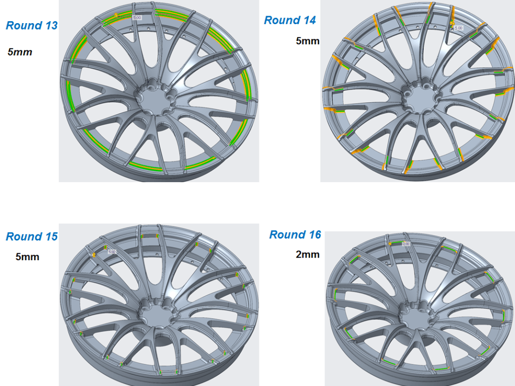
STEP 23.
Add appearance:
REAR RIM
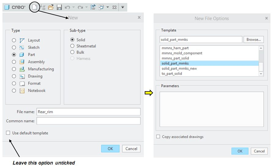
STEP 1.
Create a new Part and rename it: Rear_rim
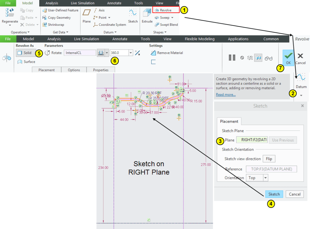
STEP 2.
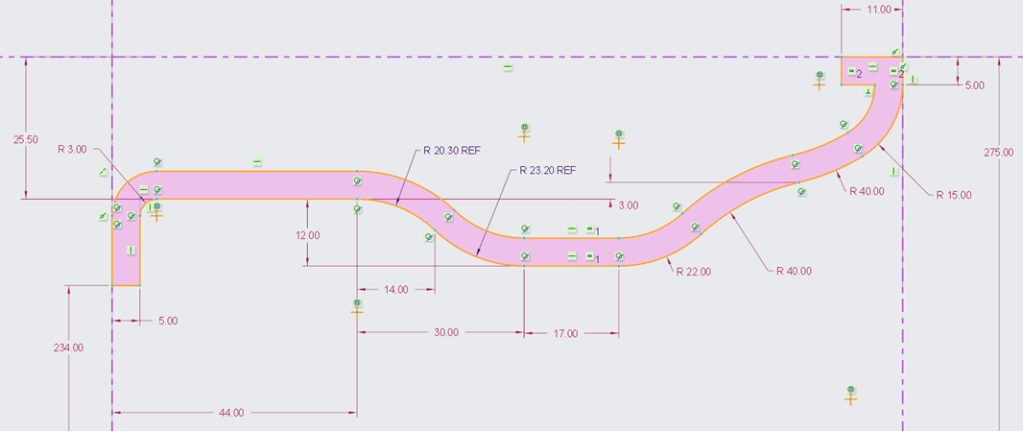
Click on Revolve icon, then on RIGHT plane draw the rim profile then revolve it completelly.
STEP 3.
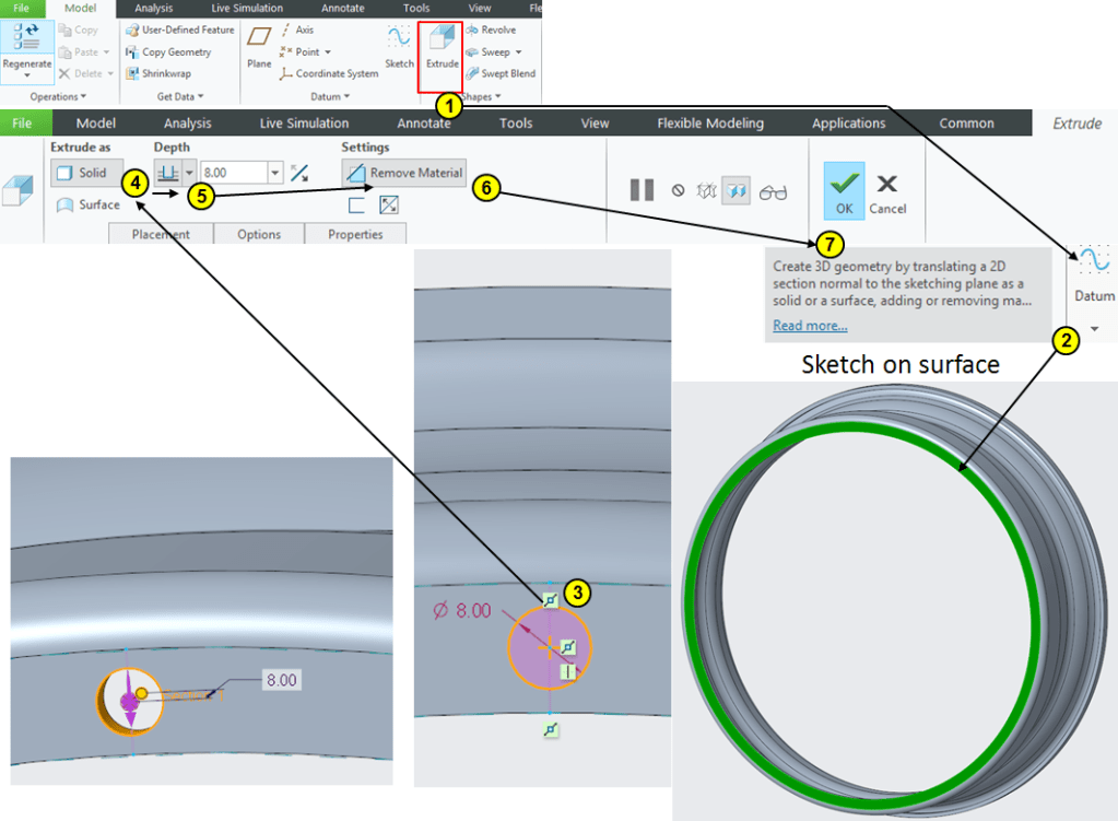
Click on Extrude icon and select the surface on the rim’s frontside. Draw a cirlce of Ø8mm and extrude it at 8mm depth:
STEP 4.
Keep the previous Extrude feature (Hole) selected in the Model Tree and click on “Patern” icon then enter the Pattern parameters for 30 instances:

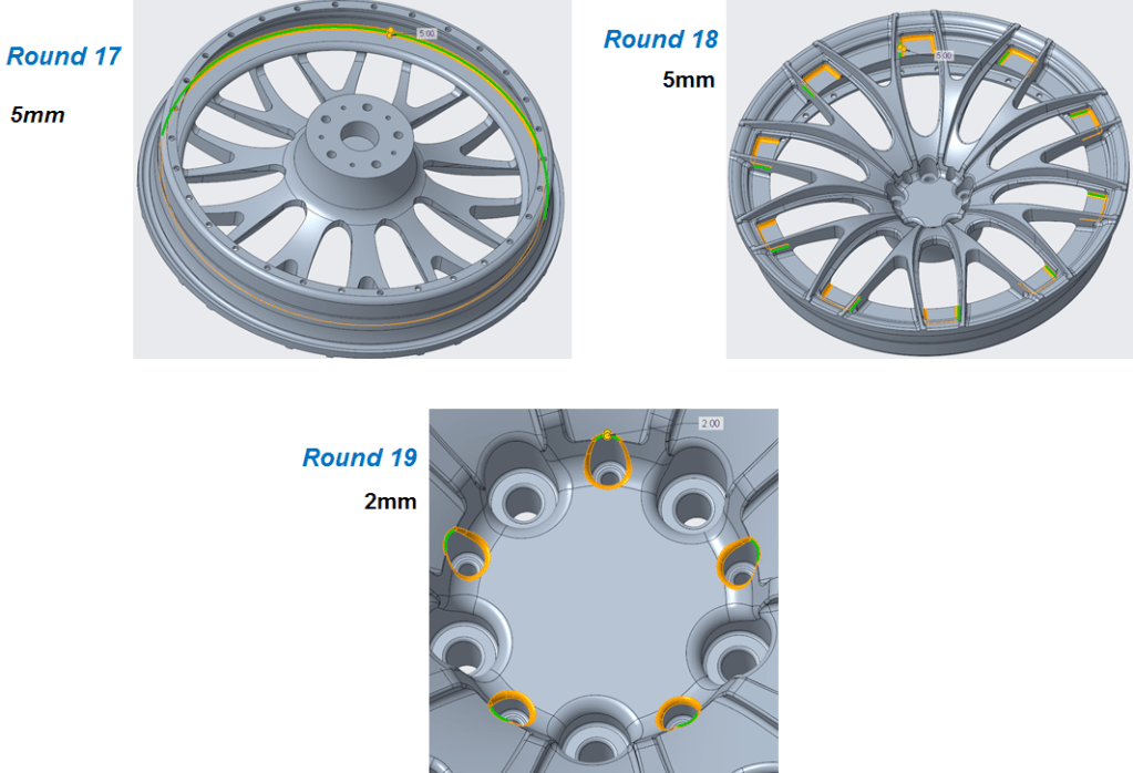
STEP 5.
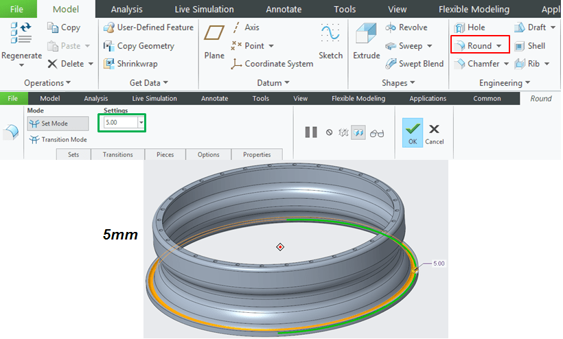
Apply a round of 5mm as shown:
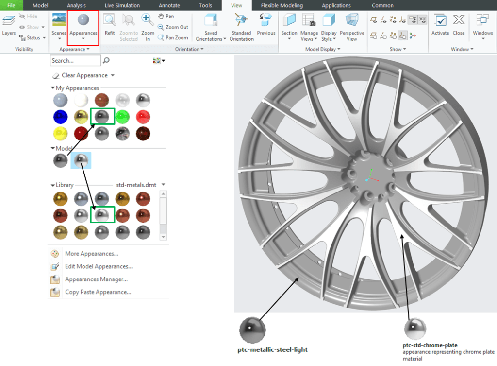
STEP 6.
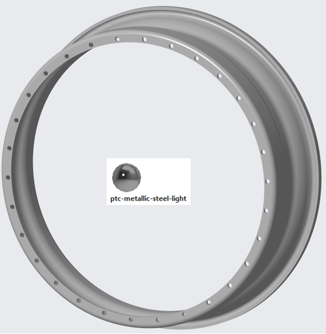
Add aprearance:
AUDI LOGO PART
STEP 1.
Create a new Part and rename it: Logo
STEP 2.
Click on Extrude icon–> select the TOP plane as sketching plane–> draw a circle of Ø85mm and extrude it at 50mm length.

STEP 3.
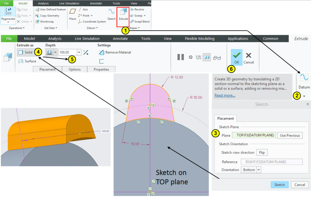
Click again on Extrude icon –> Select the TOP plane as sketching plane –> draw the profiles as shown then extrude it 100mm in length:
STEP 4.
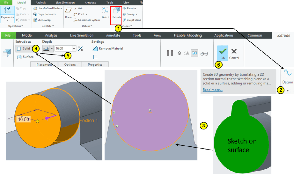
Do the 3rd Extrude as shown (at 16mm length):
STEP 5.
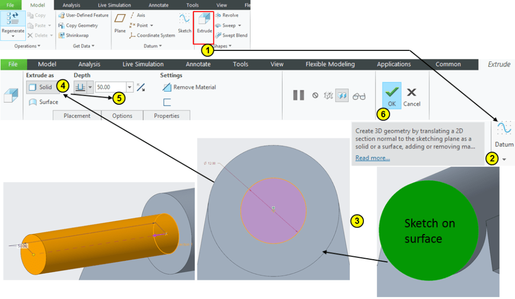
Create the 4th Extrude as Ø12mm circle at 50mm length:
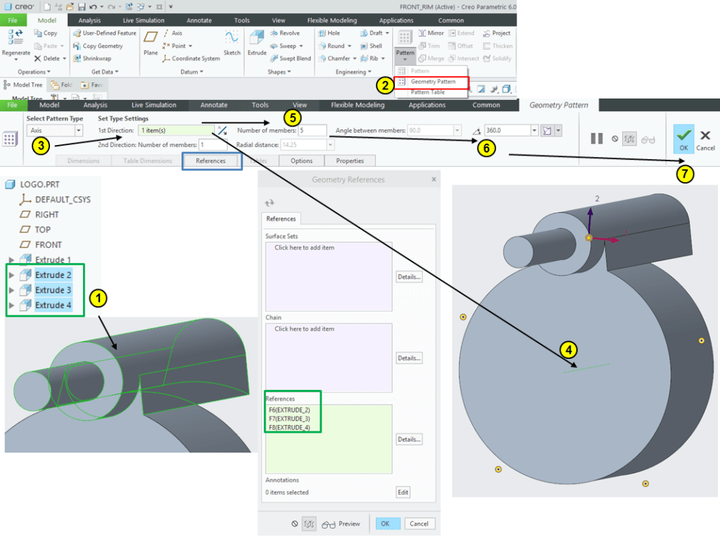
STEP 6.
Select the 2nd, 3rd and 4th Extrude in the Model Tree then click on Geometry pattern icon to generate a pattern of 5 instances:
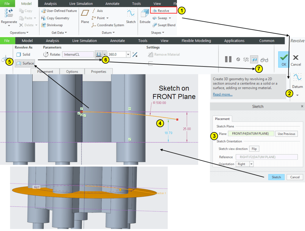
STEP 7.
Click on Revolve icon, select the FRONT plane as sketching plane and create a revolved surface as shown:
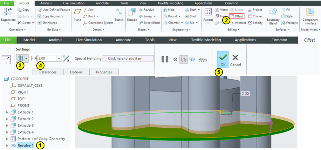
STEP 8.
With Revolve 1 feature selected in the Model Tree click on the Offset icon and create a new surface as 2mm offset from the original surface:
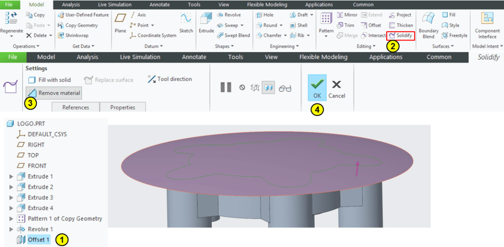
STEP 9.
Keep the Offset1 feature selected in Model Tree and click on Solidify icon –> remove the material above Offset 1 as shown:
STEP 10.
Click on Extrude icon–> Select the TOP plane as sketching plane –>draw 2 concentric circles of Ø13mm and Ø16mm –> Extrude the profile at 50mm length:

STEP 11.
Keep the previous Extrude selected in the Model Tree and click on Pattern icon to create a pattern of 4 instances normal to FRONT plane:

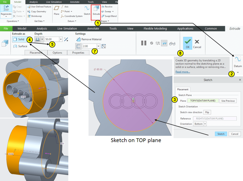
STEP 12.
Click on Extrude icon–> Select the TOP plane as sketching plane–> draw a circle of Ø65mm and extrude it 50mm in length as 2mm thick profile:
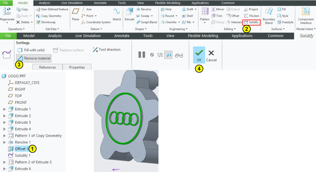
STEP 13.
Select the Offset1 feature in Model Tree and click on Solidofy icon –> Remove the material above Offset 1 as shown:
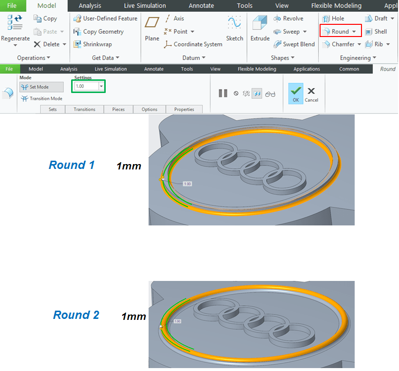
STEP 14.
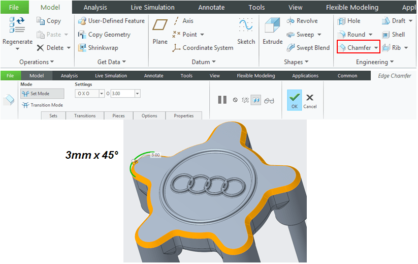
Add rounds as follows:
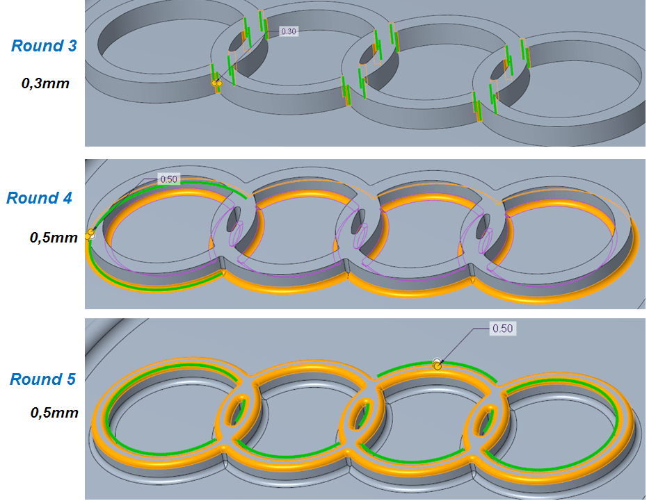
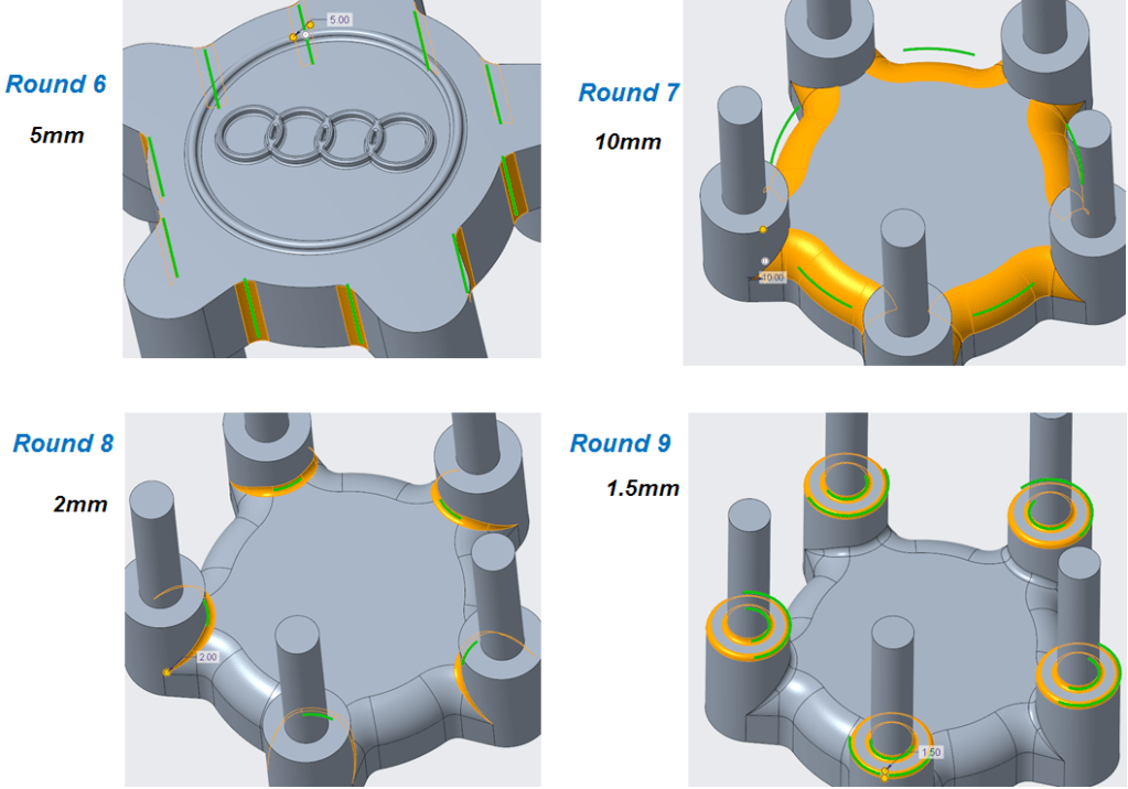
…. add a chamfer:
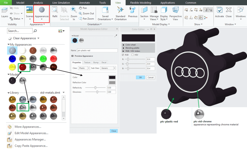
STEP 15.
Add appearance:
STANDARD PARTS
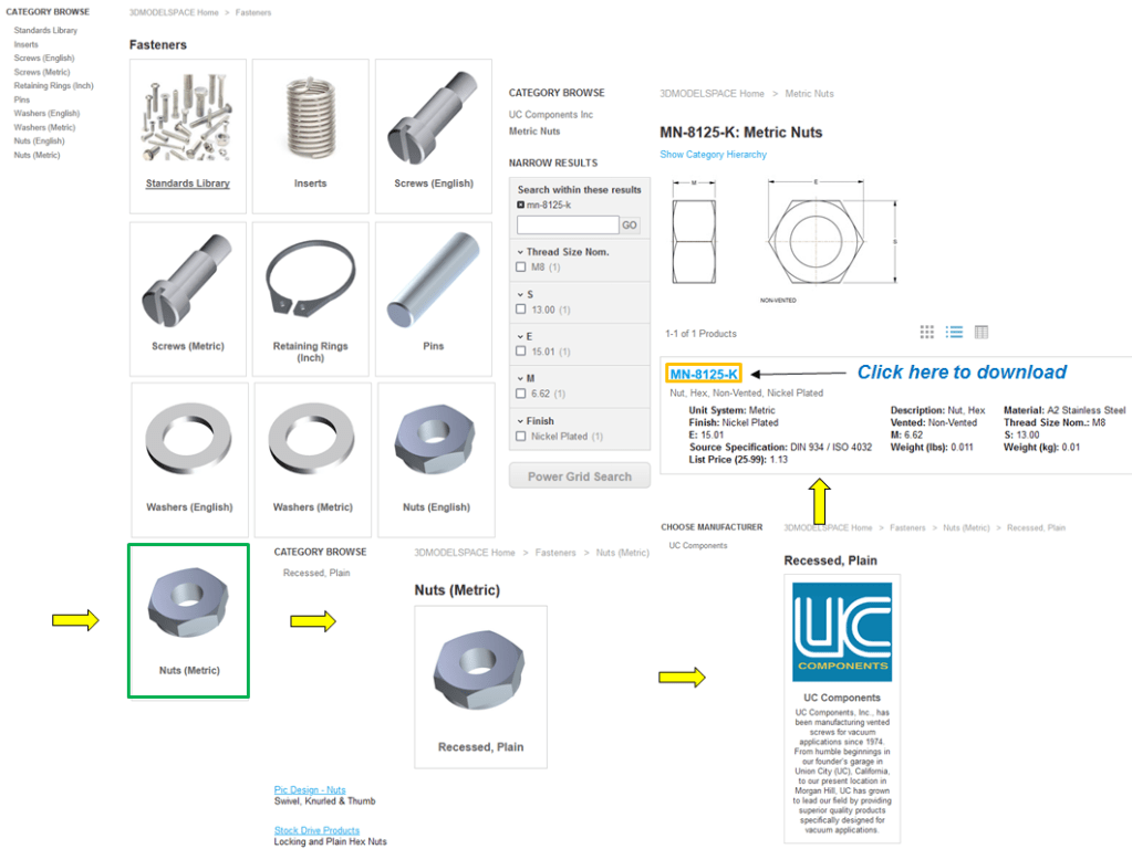
In many cases in assemblies you need standard parts such as screws, nuts, bolts, etc. these are already available from different online sources, no need to design them from scratch. My favourite website where a large variety of such parts can be taken is: https://www.3dmodelspace.com/
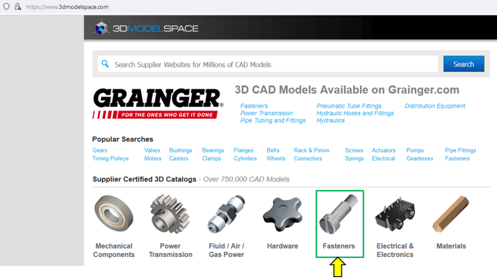
Just go on this website download the 3 needed parts as follows:
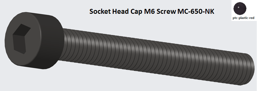
SCREW M6 Socket Head Cap, Slot-Vented = MC-650-NK
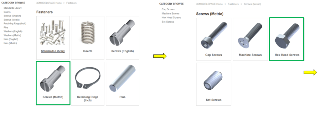
On the 3DMODEL SPACE website click on Fastenres–>Screws (metric)–>Cap Screws –>In the Search results type: mc-650-nk select and download the part MC-650-NK


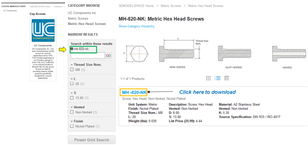
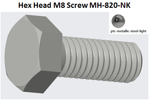
SCREW M8 , Hex Head, Non-Vented, = MH -820-NK
On the 3DMODEL SPACE website click on Fastenres–>Screws (metric)–>Hex Head Screws –>In the Search results type: mc-820-nk select and download the part MH-820-NK
NUT, Hex, Non-Vented = MN-8125-K
On the 3DMODEL SPACE website click on Fastenres–>Nut (metric)–>In the Search results type: mn-8125-k select and download the part MH-820-NK

WHEEL RIM PRODUCT
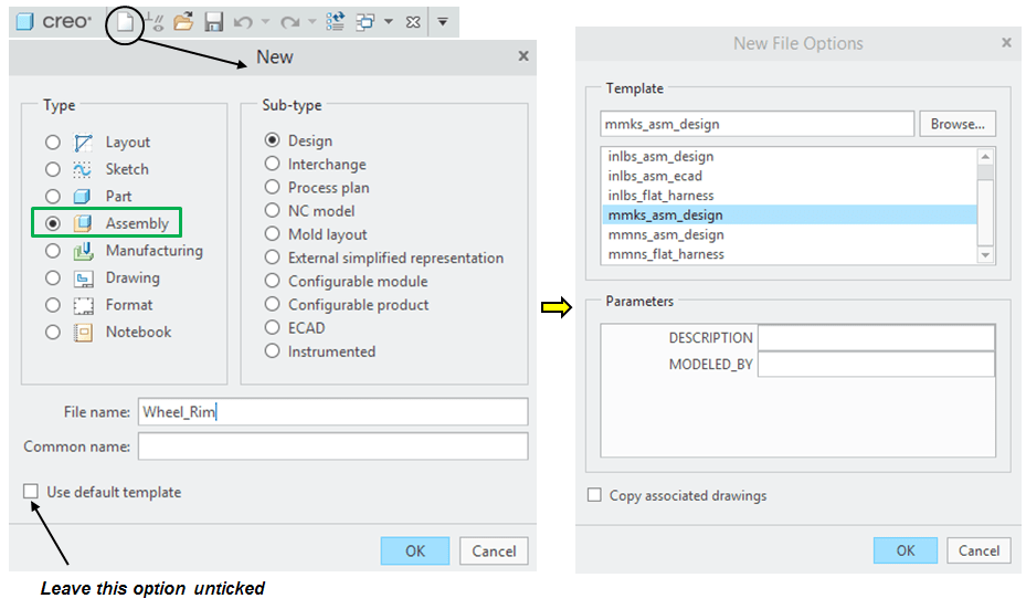
STEP 1.
Create a new Assembly and rename it: Wheel-Rim
STEP 2.
Click on Assemble icon and browse for the 1st component in project folder.–> Choose the Front-Rim past and constrain it as default position in the assemby:

STEP 3.
In the same way click on the Assemble icon to add the rest of components. Continue with the Rear_Rim part having the following constraints:

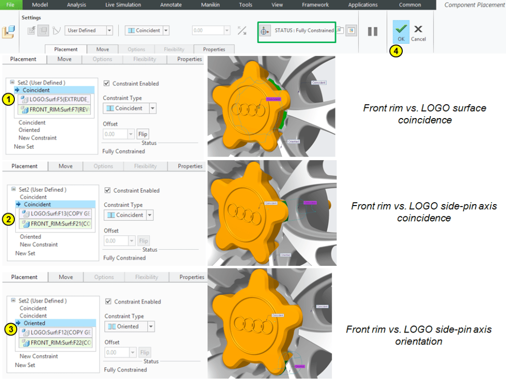
STEP 4.
Add the Logo part with the following constraints:
STEP 5.
Add the M6 screw:
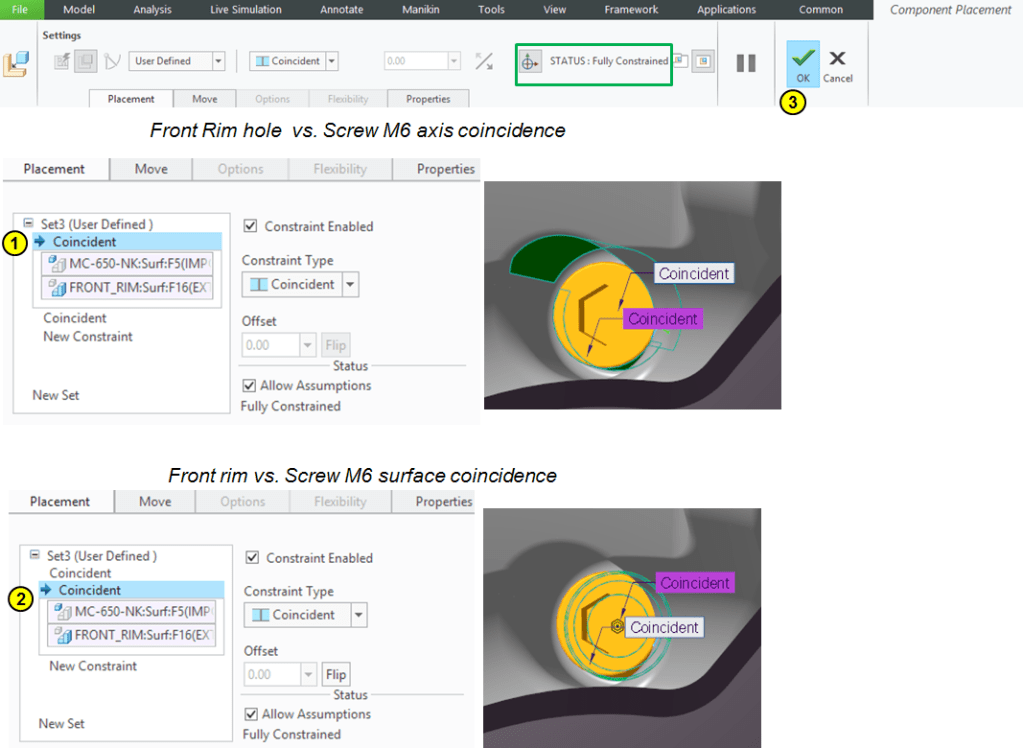
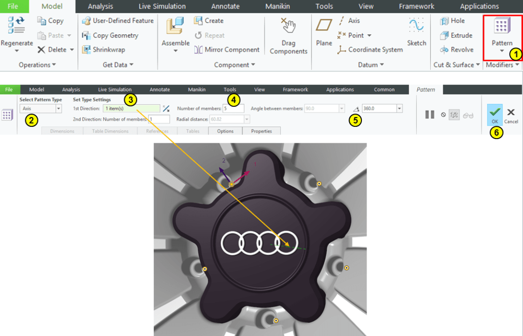
STEP 6.
Keep the M6 Screw selected in the Model Tree –> click on Pattern icon –>create a pattern of 5 instances aroud the rim axis:
STEP 7.
Add the M8 screw:
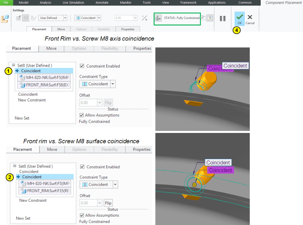
STEP 8.
Keep the M8 Screw selected in the Model Tree –> click on Pattern icon –>create a pattern of 30 instances around the rim axis:
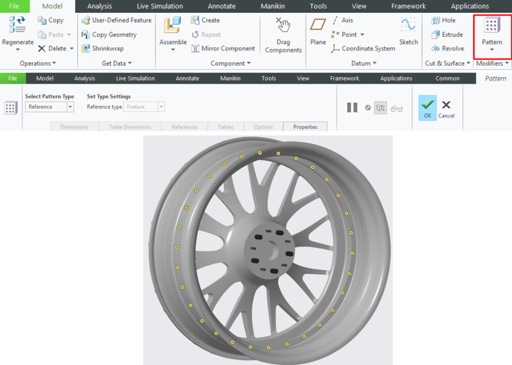
STEP 9.
Add the M8 nut:
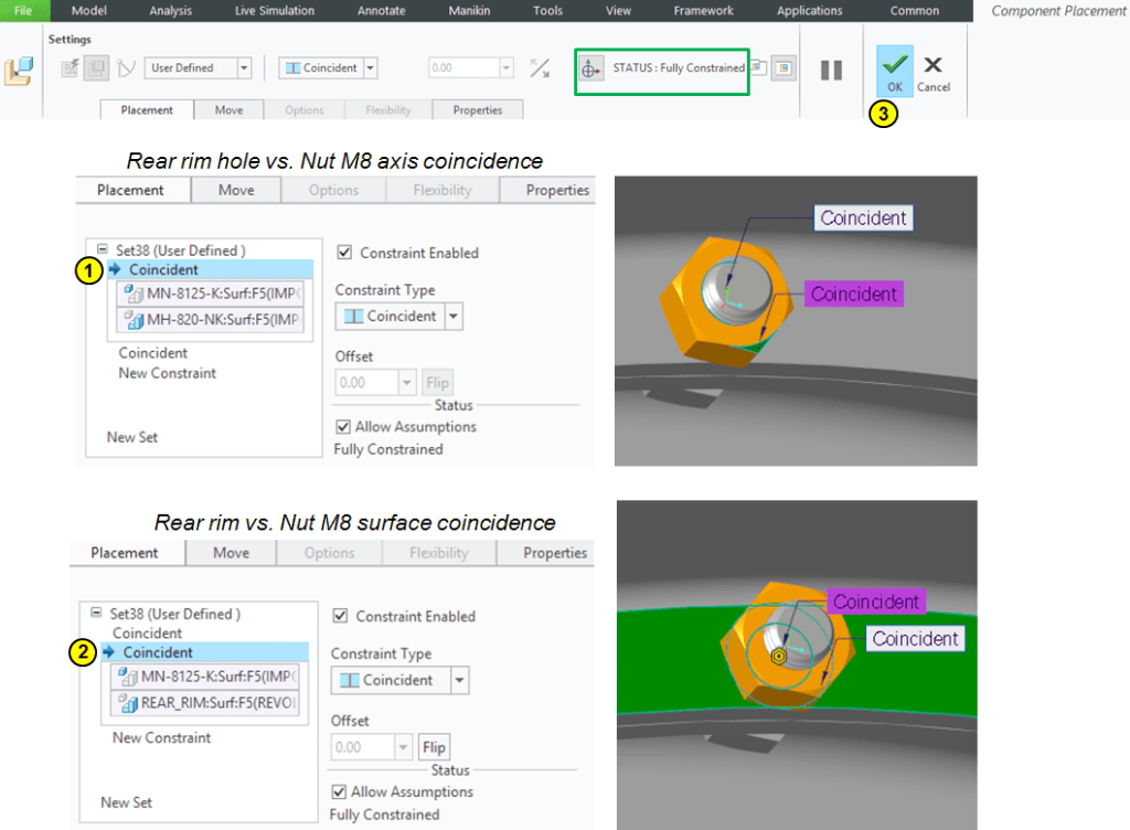
STEP 10.
Keep the M8 Nut selected in the Model Tree –> click on Pattern icon –>create a pattern of 30 instances around the rim axis:

The final assembly is ready.
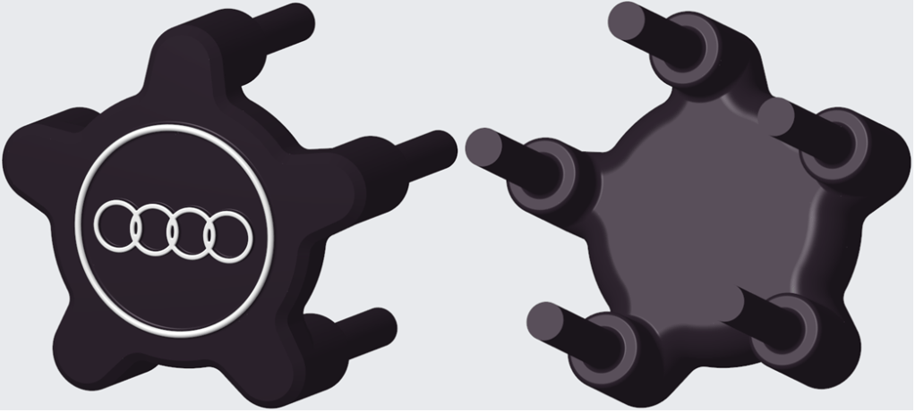
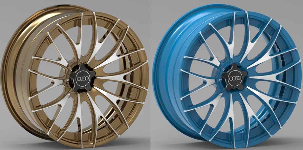
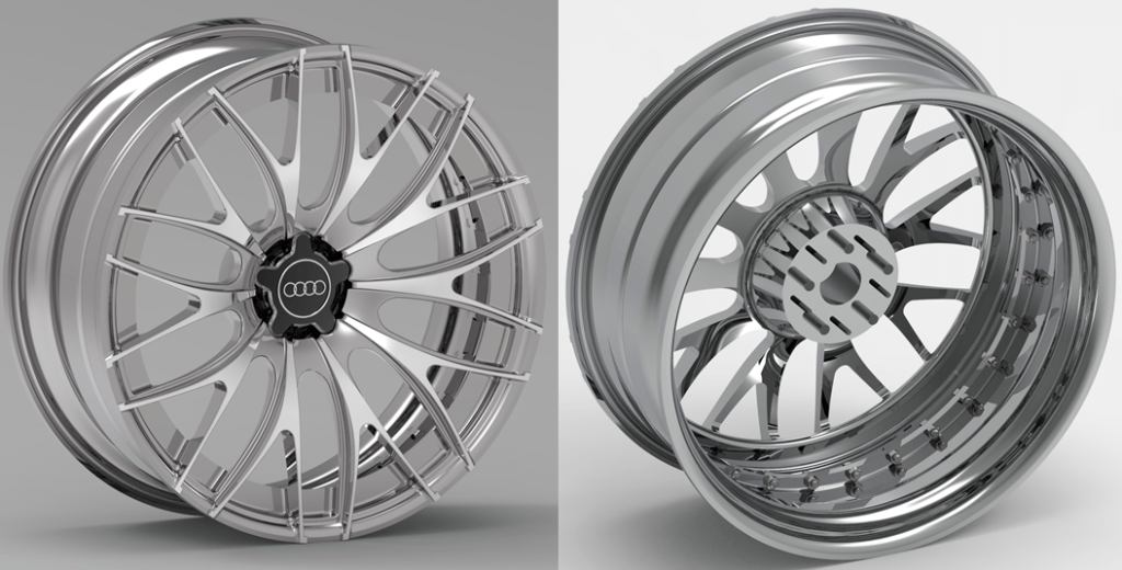
With Keyshot rendering you can apply better appearances for instance as shown below:
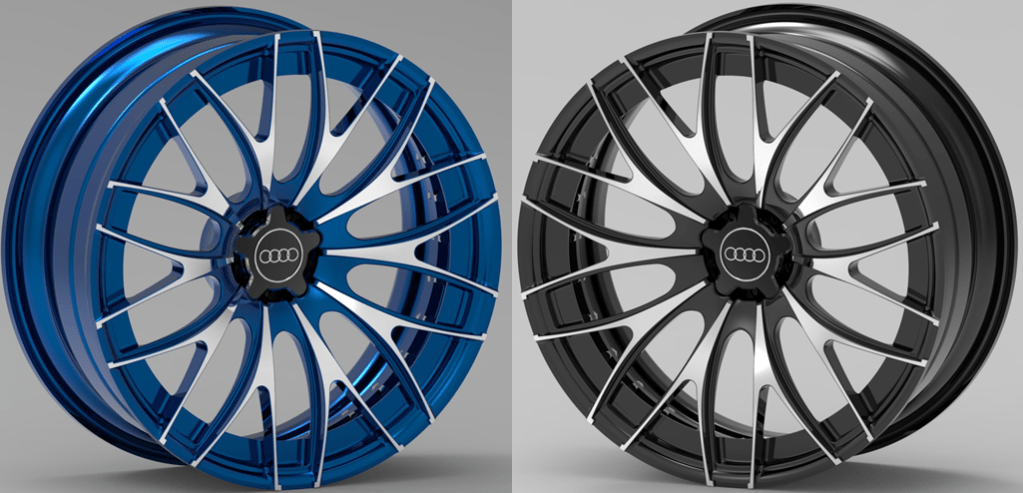
Using Keyshot rendering software you can apply some nice appearance and the final wheel rim can look like this:
This design work is also available as video version on my YouTube channel as embedded below:

Thank for sharing your knowledge, it’s a great way.
LikeLike
You’re welcome ;-). I am glad you liked it, In case you have a particular interest in a topic about CAD and/or Materials Science, don’t hesitate to mention it your future comments, and I’ll be glad to share more content about that.
LikeLike