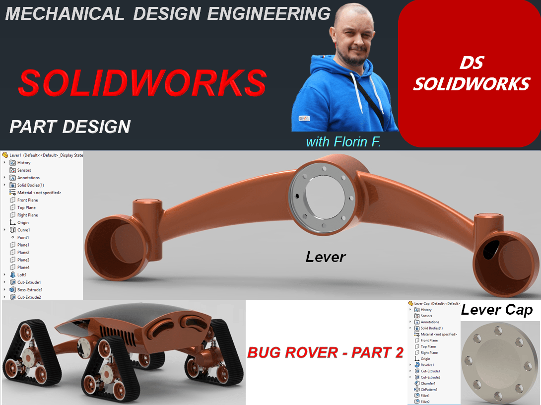
In this 2nd part of design work for the Bug Rover, I’ll show you the next 2 main components: The Lever and The Lever Cap. Let’s start:
THE LEVER
STEP 1

Create new part
STEP 2
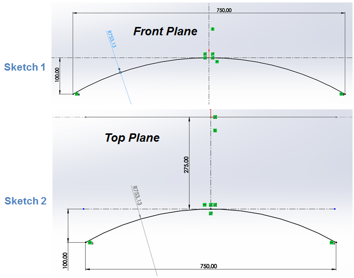
Create the following 2 sketches:
STEP 3
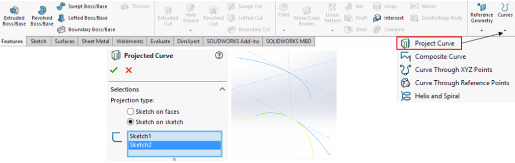
Use the previous 2 sketches to create a Project Curve
STEP 4
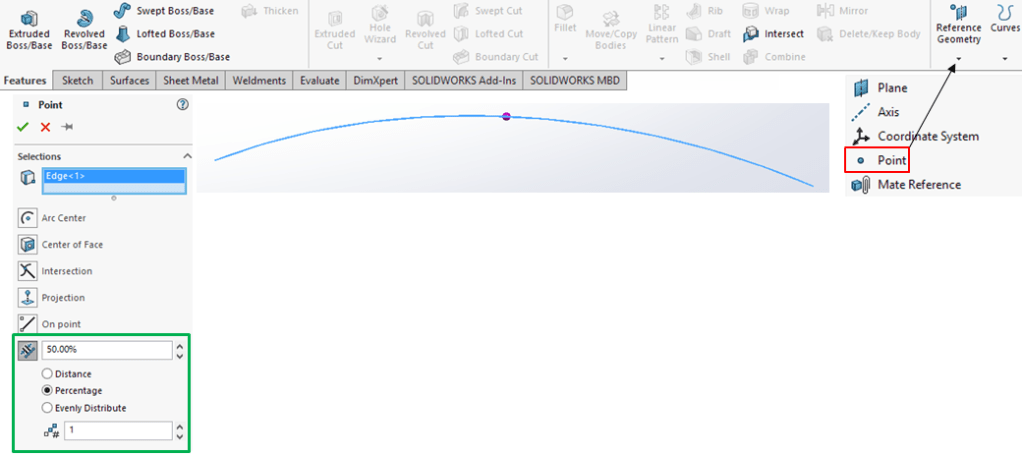
On the Projected Curve create a middle point:
STEP 5
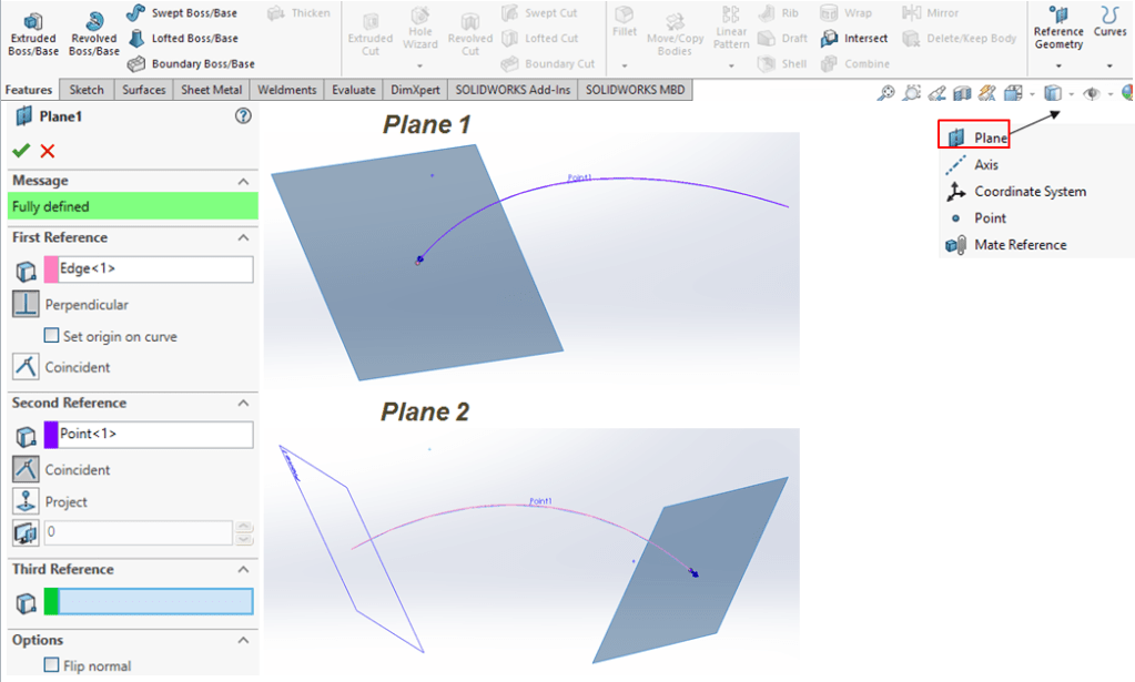
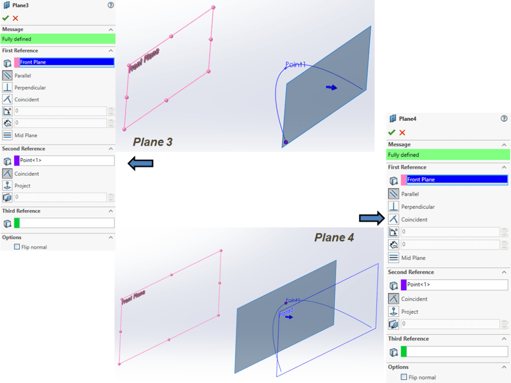
Create the 4 new datum planes necessary for the construction of the next features, as follows:
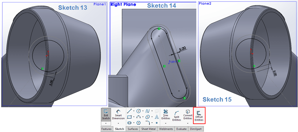
STEP 6
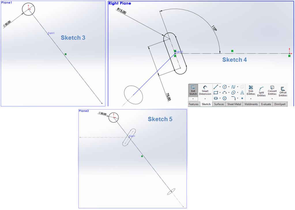
On Plane 1, Right Plane and Plane 2, draw the needed sections for the definition of the lever’s form, as follows:
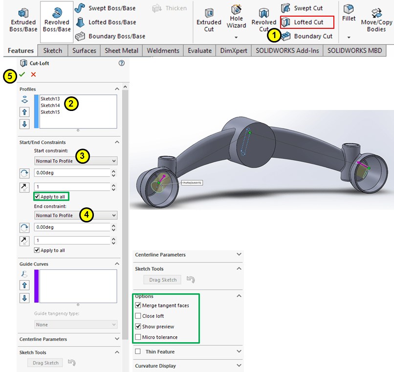
STEP 7
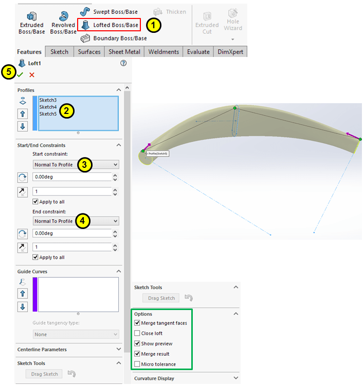
Using the 3 previoulsy created sections, create a Lofted Boss feature as shown:
STEP 8
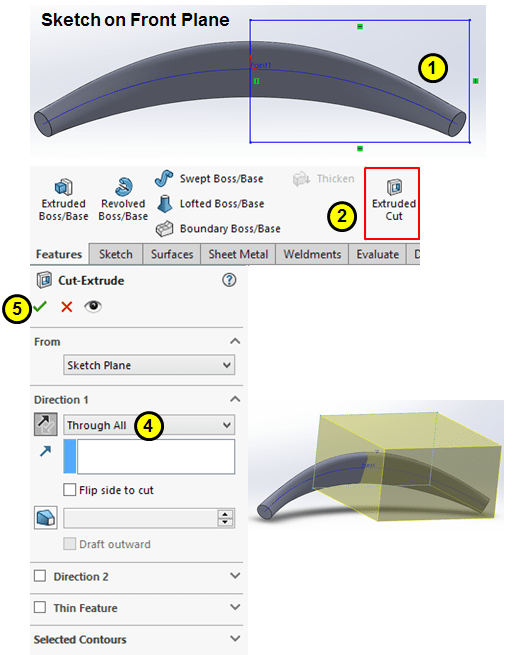
Create a dimensionless profile big enough the cover one half of the current body and cut-extrude it through all.
STEP 9

On the circular section, sketch a circle of Ø120, then extrude it 30mm straight ahead in direction 1 and put it 55mm backwards at 20° in direction 2.
STEP 10
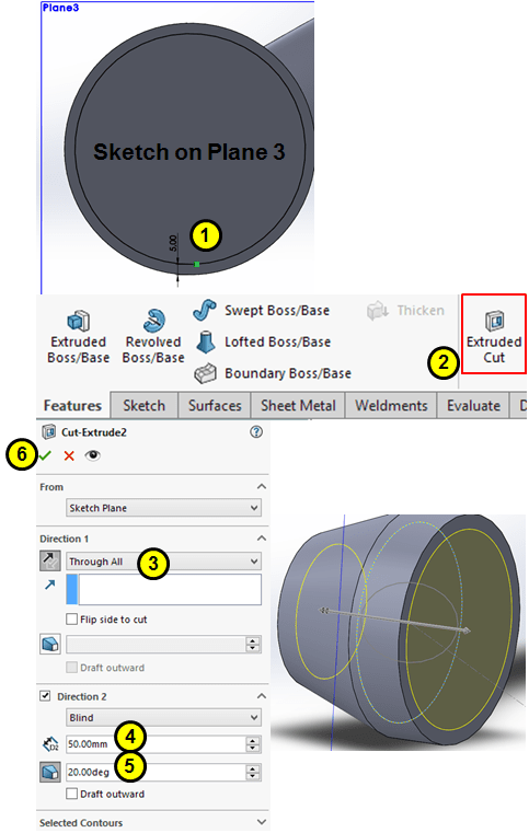
In similar way as done at the previous step, on Plane 3 sketch a circle as 5mm offset inwards from the outer edge and cut-extrude it in 2 direction, as through all in direction 1 and 50mm at 20° in direction 2.
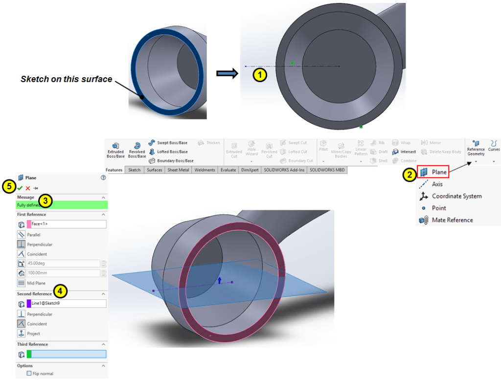
STEP 11
Use the front surface to draw a horizontal construction line, then create a new datum plane having the reference the constucton line and front surface:
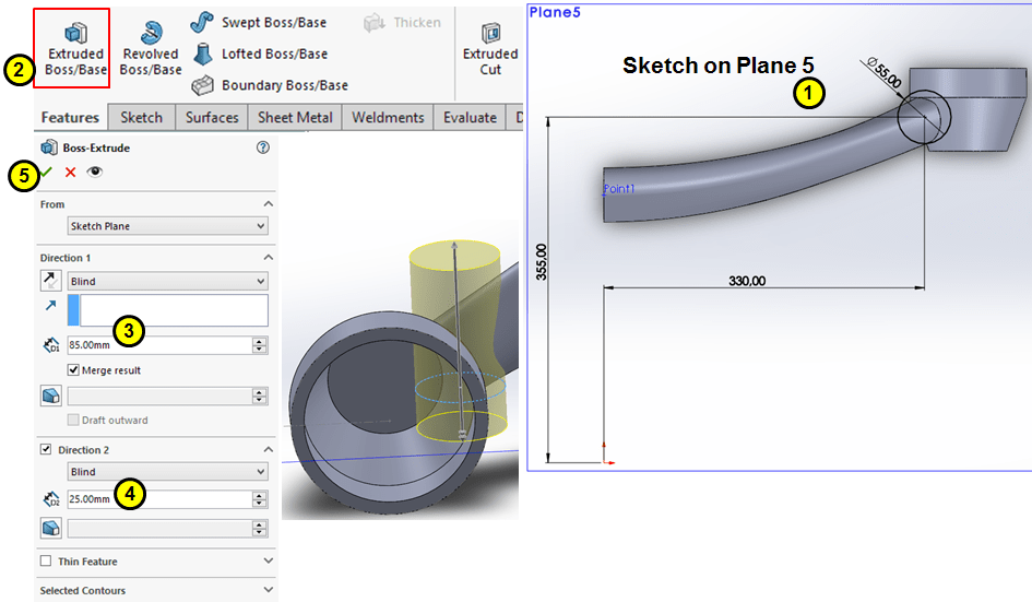
STEP 12
Draw a circle of Ø55 on the Plane 5, then Extrude it in both diretions, 85mm upwards and 25mm downwards:
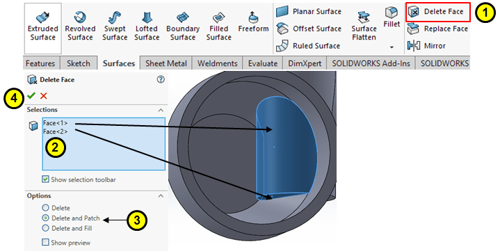
STEP 13
Delete the unnecessary faces created by the previous extrude feature:
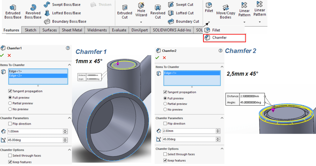
STEP 14
Add chamfers as follows:
STEP 15
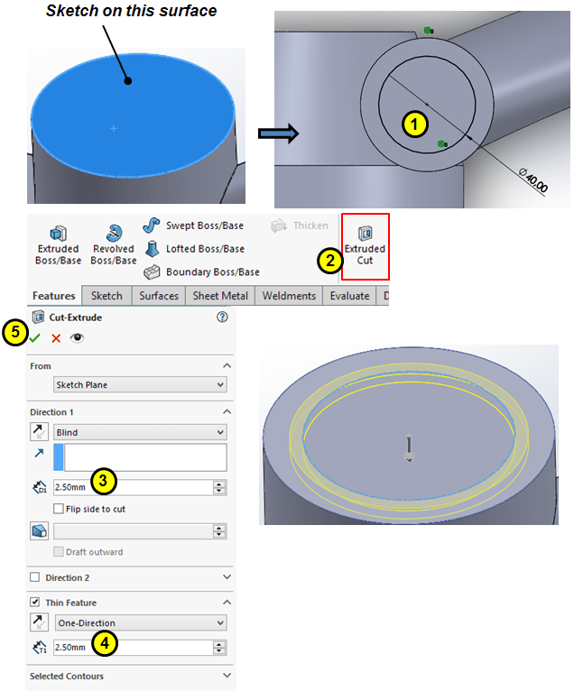
Create a 2,5mm thin feature as 2,5mm deep cut extrude on the top side of the boss created at Step 12.
STEP 16
Add 5 fillets as shown:

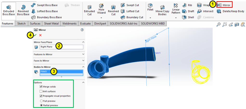
STEP 17
Use the Right Plane to mirror the current body:
STEP 18

On Plane 4 sketch a circle of Ø140 in the origin point and extrude it in both directons, 40mm ahead and 60mm backwards
STEP 19
Make 3 new sections as 5mm inward offset from the initial sketches done at Step 6
STEP 20
With previously created sections, add a Lofted Cut feature as follows:
STEP 21
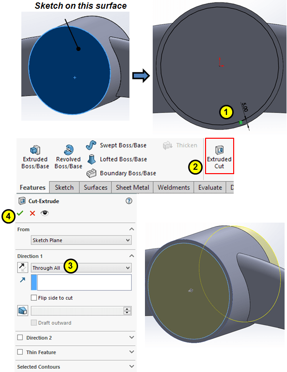
On planar surface from the middle boss, sketch a 5mm offset circle from the outer edge and cut-extrude it through all.
STEP 22
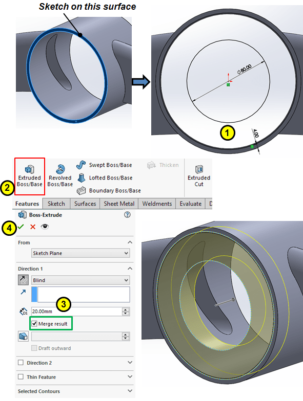
Create another extrude feature on the front side as shown:
STEP 23
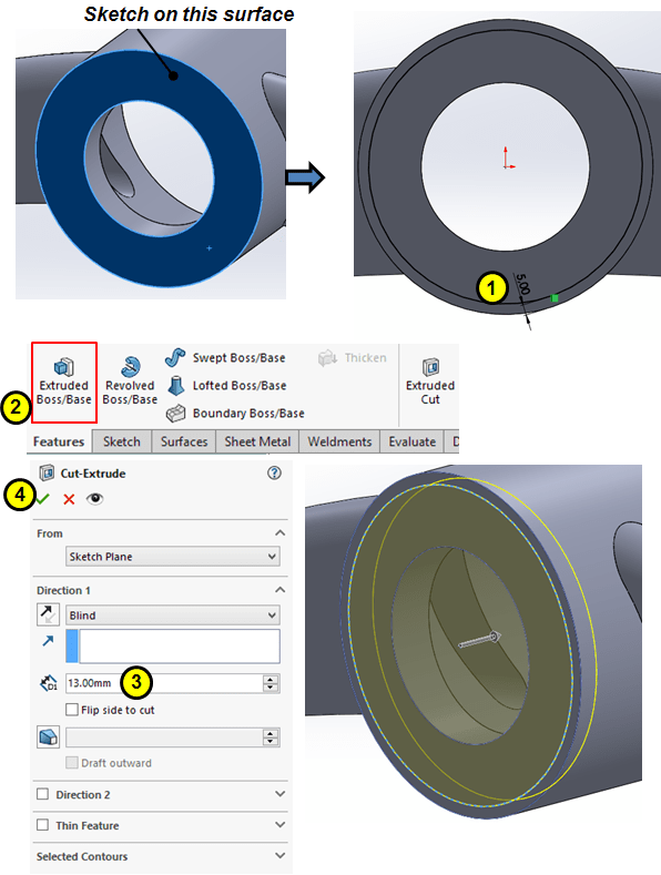
Remove material on front side with a circular extrude 13mm deep
STEP 24
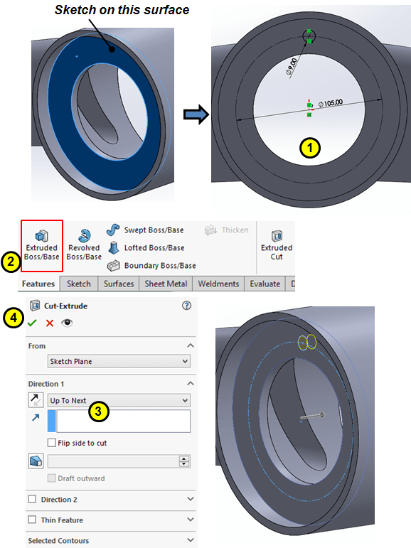
Sketch a Ø9 circle on inner planer surface, and cut-extrude it up to next
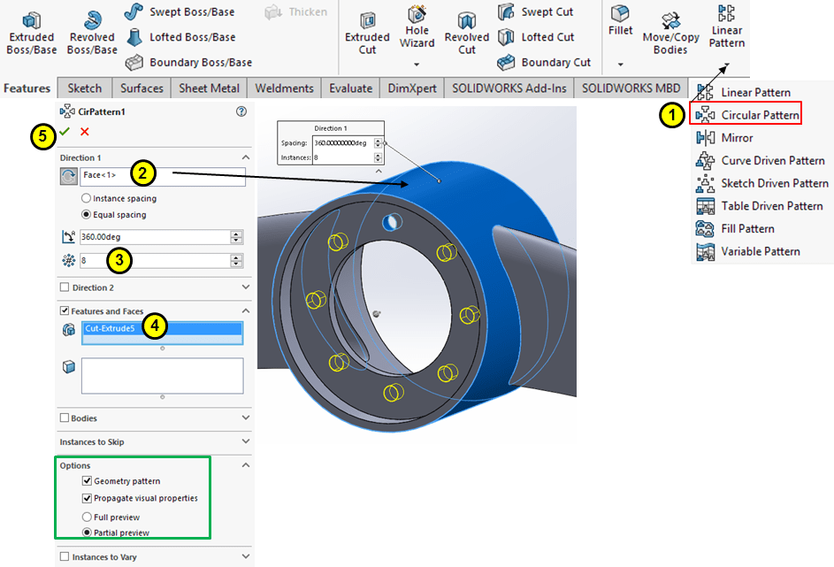
STEP 25
Circular pattern the previous cut-extrude around the outer surface for 8 instances:
STEP 26
Add chamfer on the inner edges

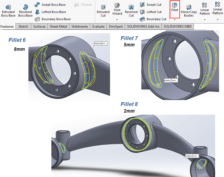
STEP 27
Add fillets as shown:
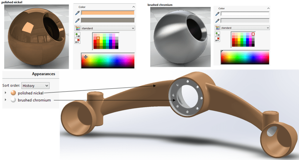
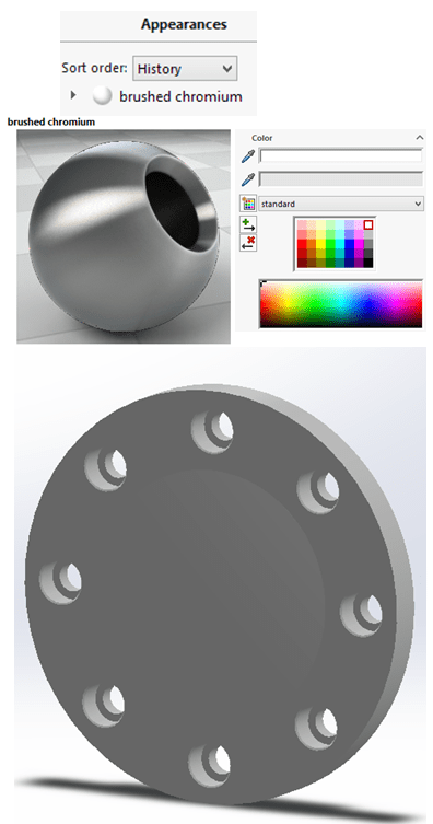
STEP 28
Add appearance
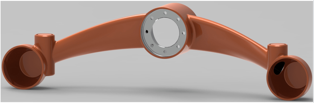
…with a better rendering in KeyShot the final part could look like this:
THE LEVER CAP
STEP 1
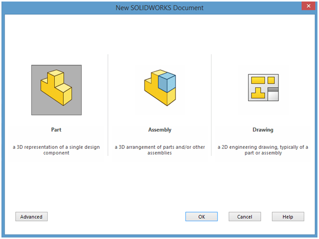
Create a new part
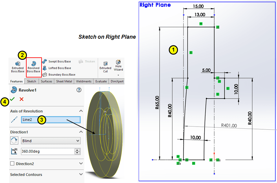
STEP 2
On Right Plane draw the following sketch and create a complete revolved feature:
STEP 3

Draw a construction circle of Ø105mm and a cicle of Ø9mm on the front face, then cut-extrude it through all
STEP 4
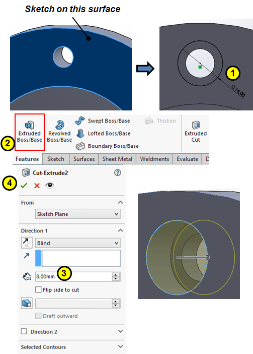
Create a counterbore on the previous feature as shown:
STEP 5
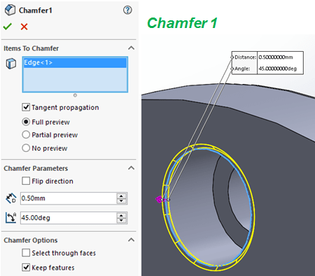
Add chamfer on the upper counterbore edge
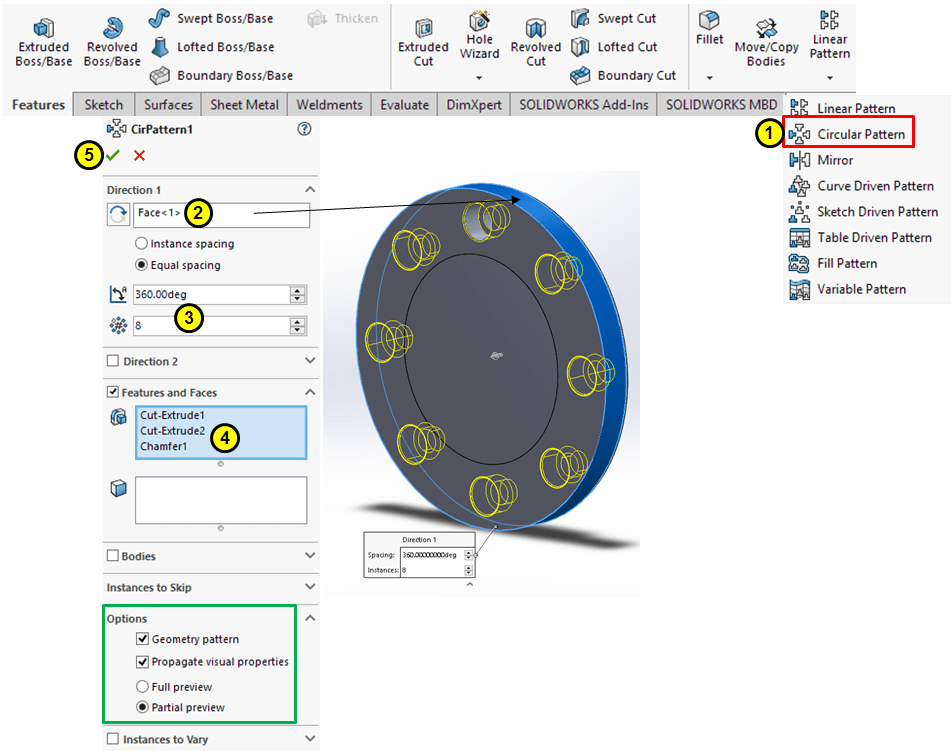
STEP 6
Circular pattern the last 3 features around the outer circular surface for 8 instances
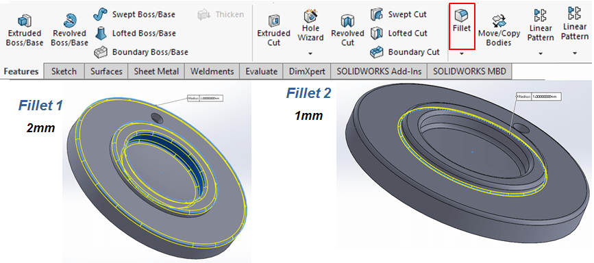
STEP 7
Add fillets
STEP 8
Add appearance

…with a better rendering in KeyShot the final part could look like this:
This design work is also available as video version on my YouTube channel as embedded below:

Leave a comment