
A rover design work implies a lot of details and components. In this article I want to present you a simplified version of a reover concept I did, which is inspired from the insects world. It really looks like a bug, so I name it Bug Rover. I will only put here the main bodies to show you the product. This is a full SOLIDWORKS job. Let’s start.
THE CABINE
The main body is the part called CABINE. This is a symmetric element so I’ll only work for one half and when it’s finished I’ll mirror everything by the mid-plane.
STEP 1
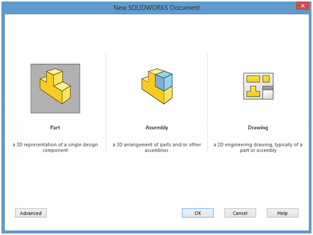
Create New Part
STEP 2
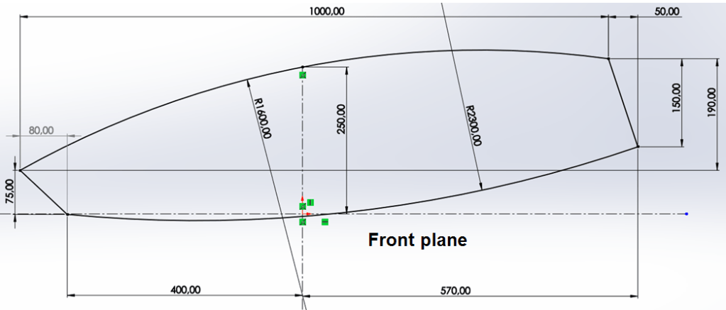
Create the 1st sketch (which will be used as skeleton) on the front plane as shown below:
STEP 3
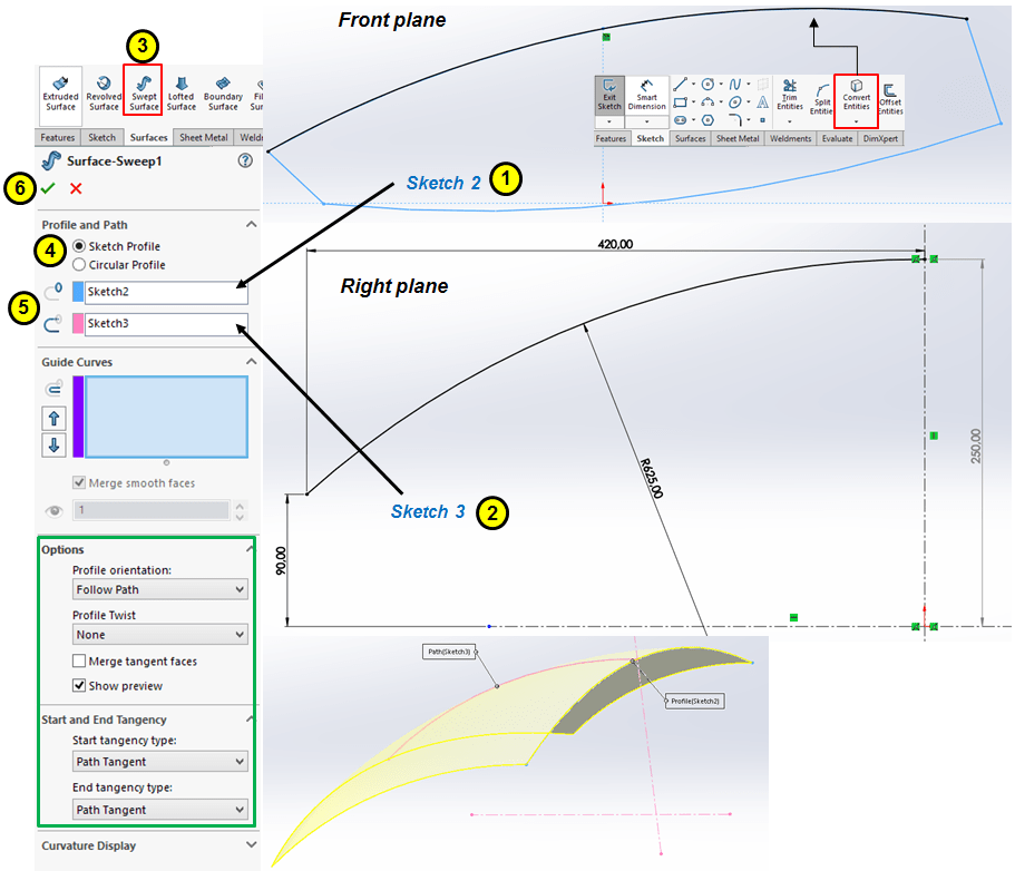
Create the 2nd skech on the Front plane and the 3rd on the Right plane , then use these to create a Swept surface as shown below:
STEP 4
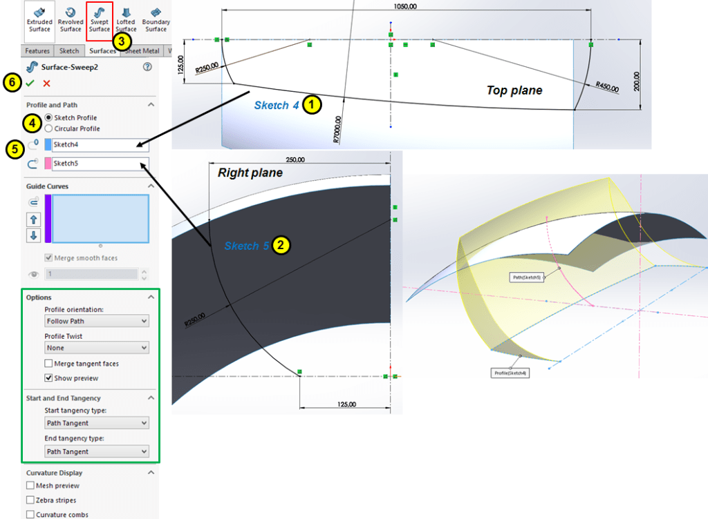
Create the 2nd Swept Surface in a similar way as the provious one as shown:
STEP 5
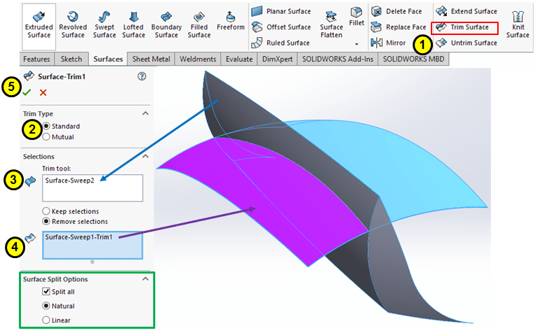
Trim the the surfaces as shown:
STEP 6
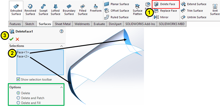
Delete the sidewide surfaces
STEP 7
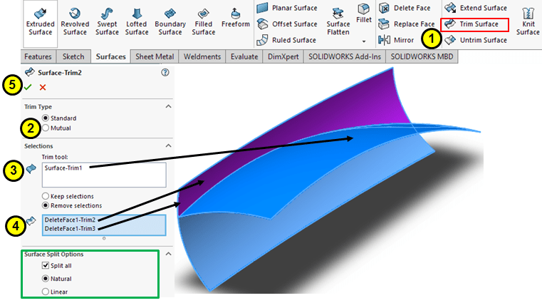
Trim the surface on the upper side
STEP 8
Create a Ruled Surface at on the rear side as shown:

STEP 9
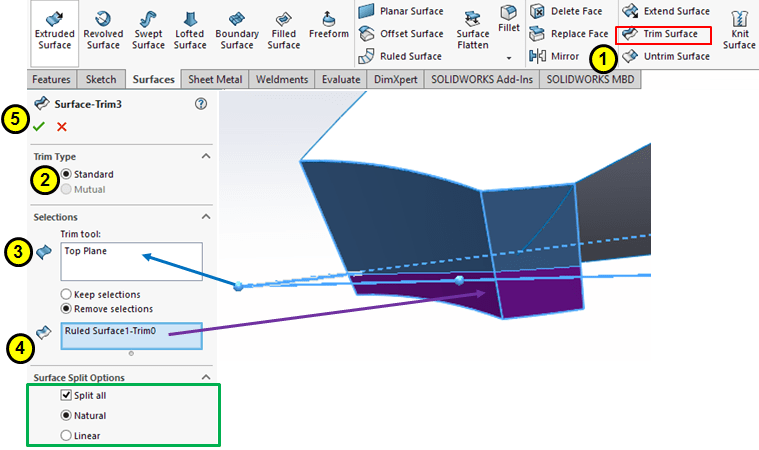
Trim the previous Ruled Surface by the Top Plane:
STEP 10
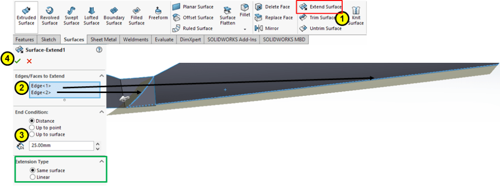
Extent the sidewise surface about 25mm more.
STEP 11
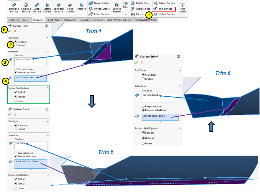
Continue triming the surfaces as shown:
STEP 12

Create a Ruled surface on the Front side.
STEP 13
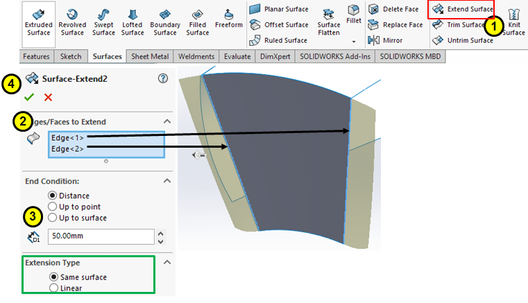
Extend the Ruled surface on sides with 50mm more.
STEP 14
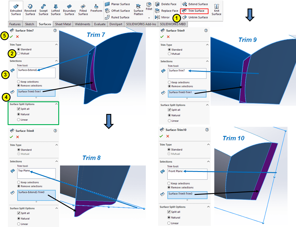
Trim the surfaces on the Front side as shown:
STEP 15
Extend the front surfaces on the edges resulted from the previous trimming operations.
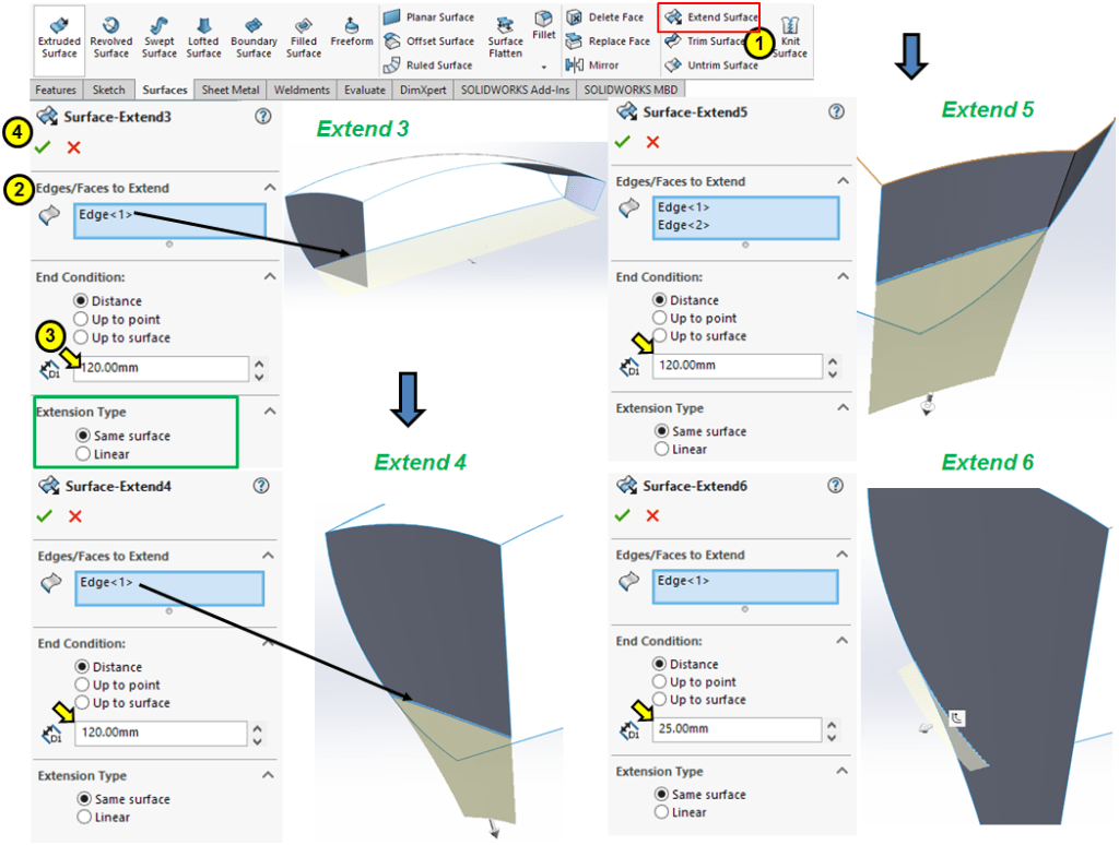
STEP 16
Trim the front sufaces on lower side as shown:
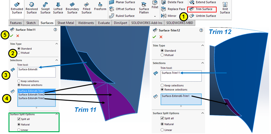
STEP 17
Extend the lower surface about 25mm more:
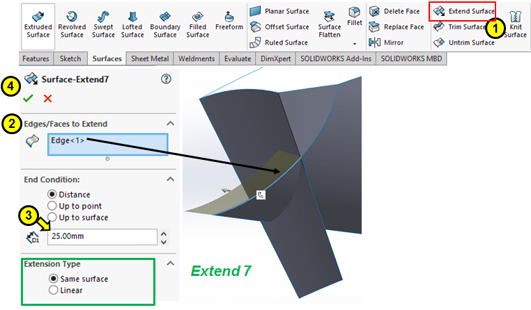
STEP 18
Trim the surfaces on the rear side as shown:
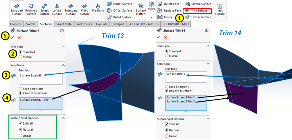
STEP 19
Create a new bottom surface by extruding a skeched profile on front plase as shown:
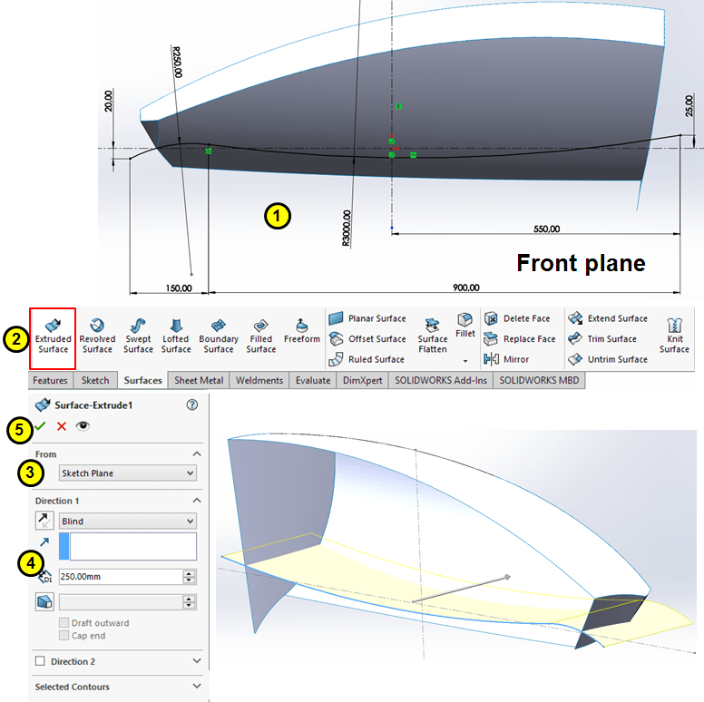
STEP 20
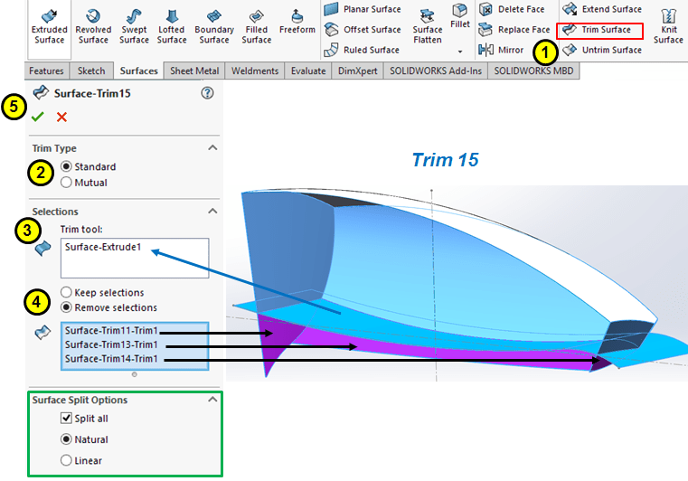
Trim the side surfaces with the bottom surface:
STEP 21
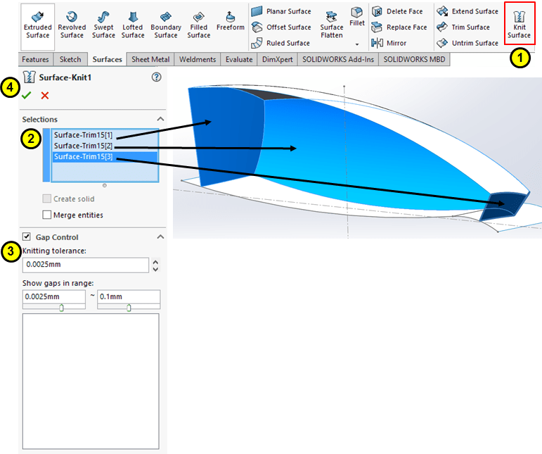
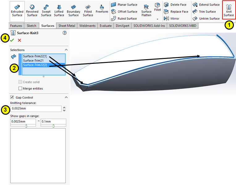
Knit the front, rear and sidewise surface:
STEP 22
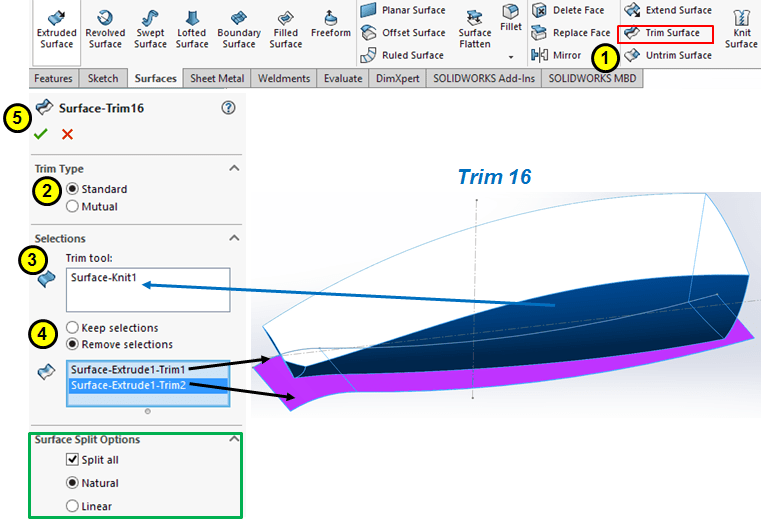
Trim the bottom surface with the previous knit:
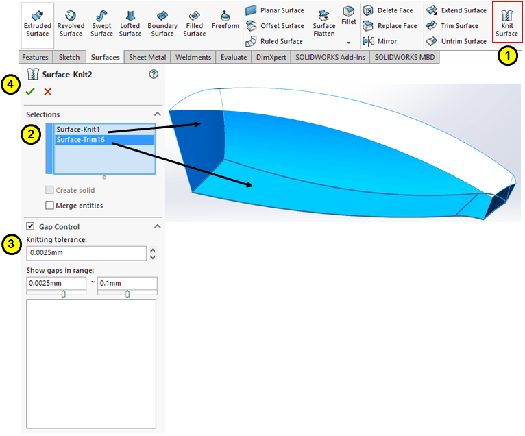
STEP 23
Except the upper surface, knit all others.
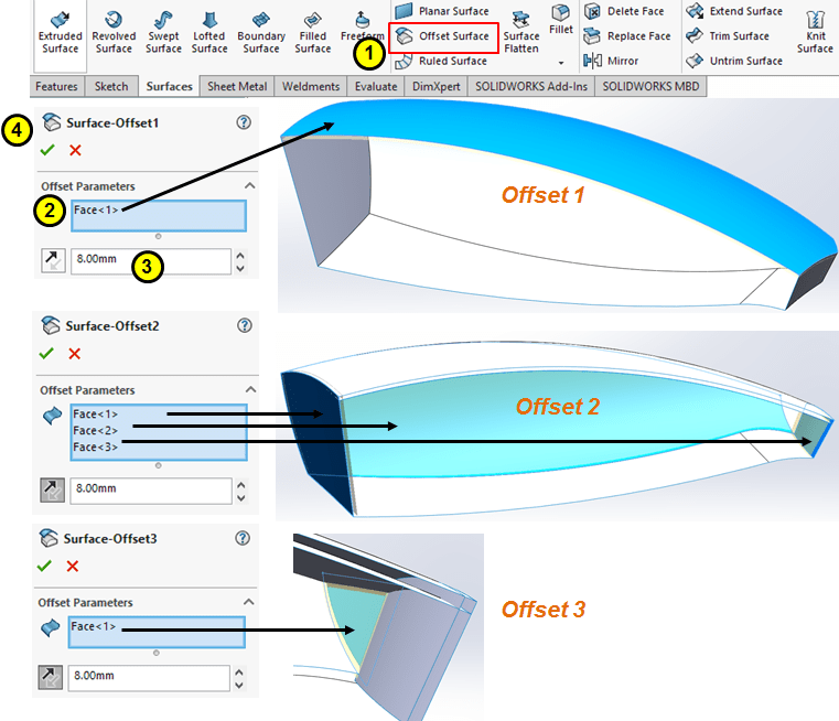
STEP 24
Create 8mm offset surfaces inward:
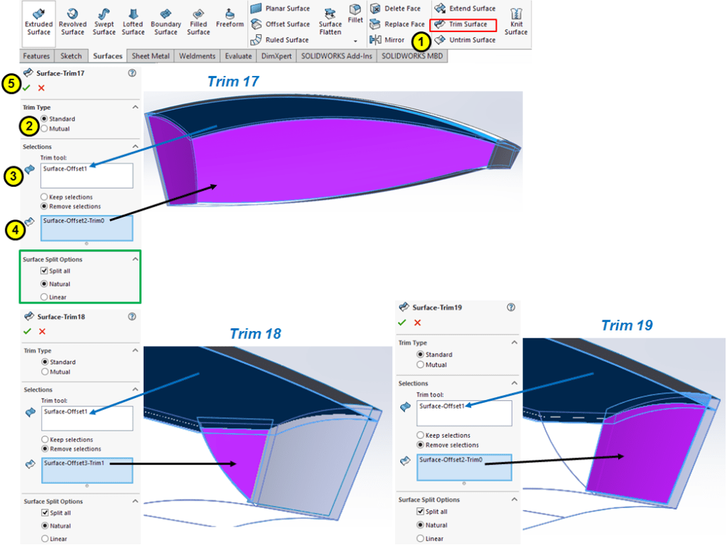
STEP 25
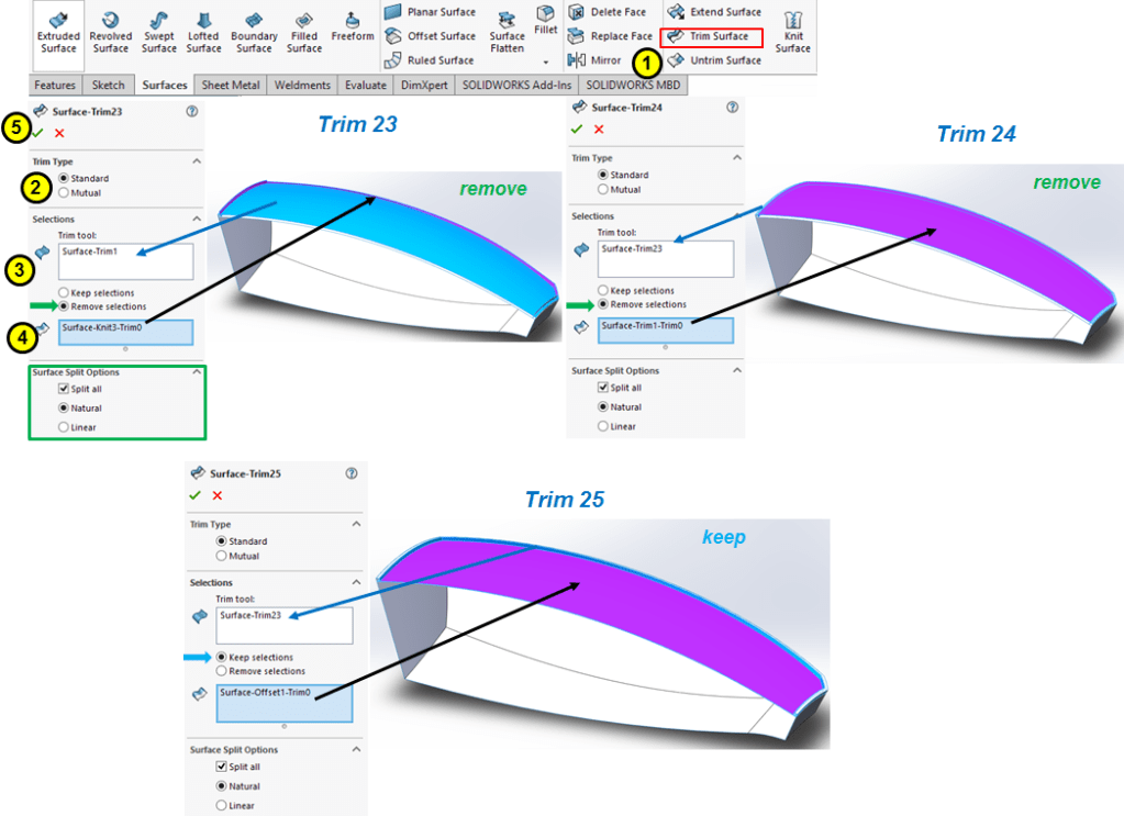
Trim the inner offset surfaces as shown:
STEP 26
Extend the previously trimmed surface by extra 10mm upwards:

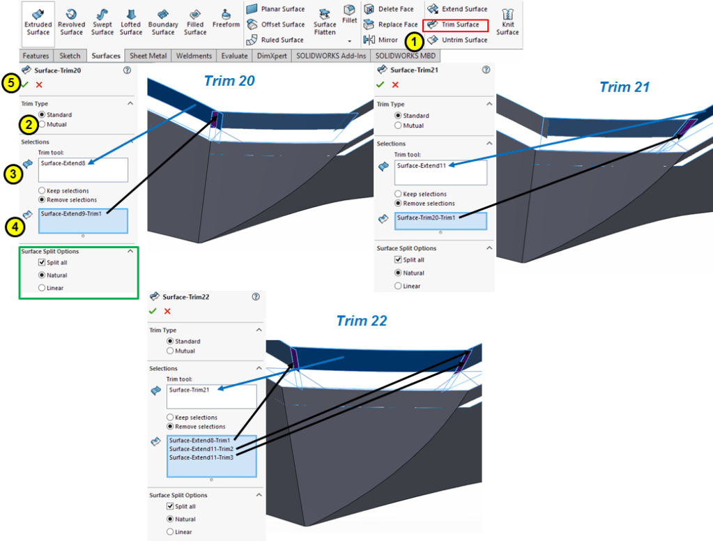
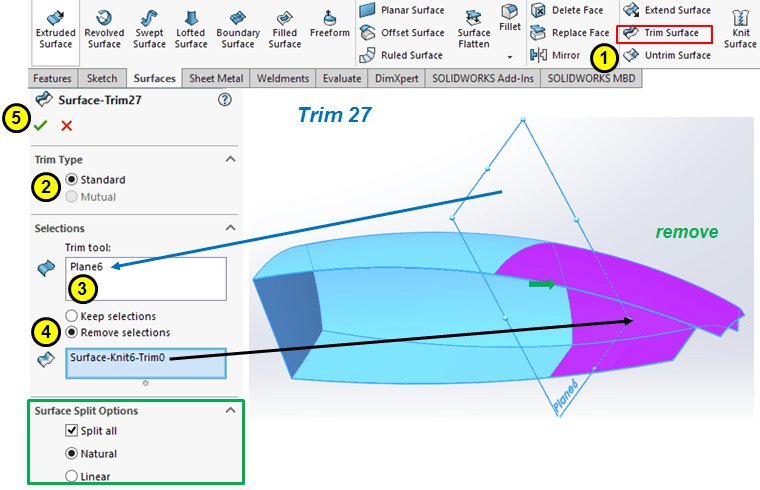
STEP 27
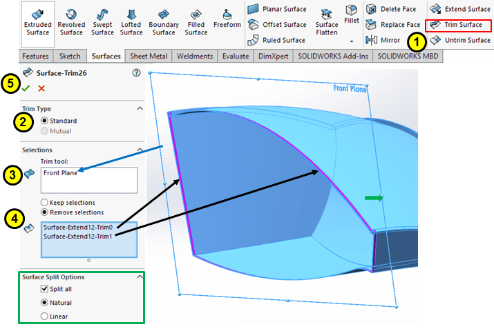
Trim the previouly extended surfaces as shown:
STEP 28
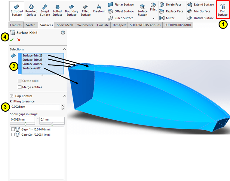
Knit the inner surfaces:
STEP 29
Trim the upper surface as shown:
STEP 30
Knit all surfaces:
STEP 31
Extend all surfaces with 5mm on the open side:
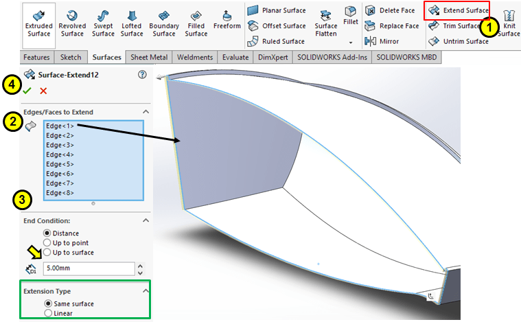
STEP 32
Trim everything by Front Plane:
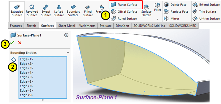
STEP 33
Close the open side with a Planar Surface
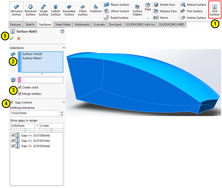
STEP 34
Knit all surfaces and create a full solid body:
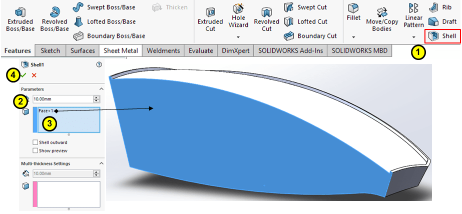
STEP 35
Shell the body with 10mm thickness from the planar face:
STEP 36
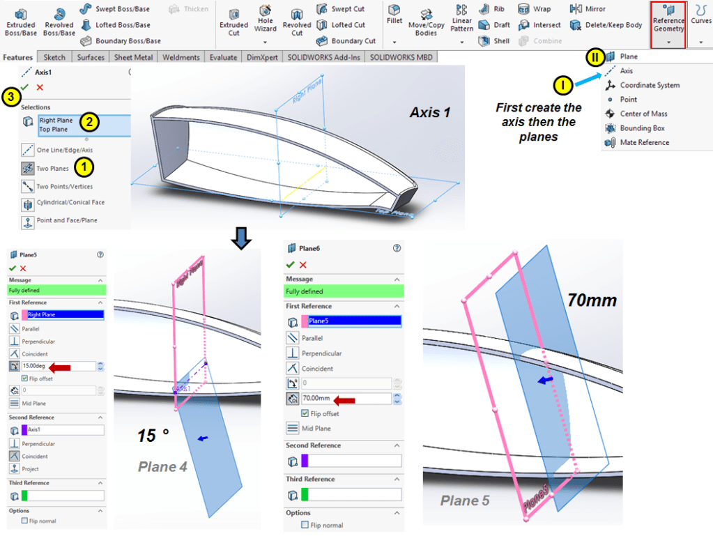
Create 5 new reference planes and a new axis as shown:

STEP 37
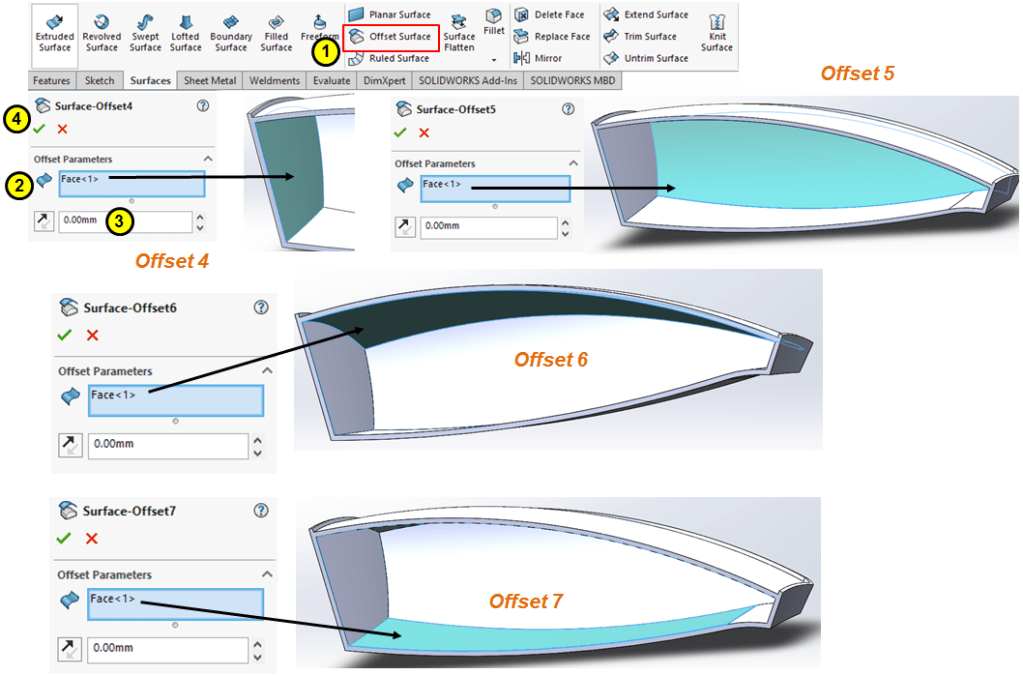
Extract the inner surfaces by an offset of 0mm as shown:
STEP 38
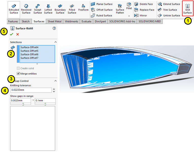
Knit the 4 inner extracted surfaces:
STEP 39
Before to continue trimming the previous knit, for a better visibility on the working model, go to Model tree and under Solid Bodies box put the curently existing Shell body on hide mode….
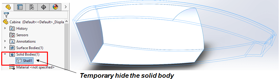
… then click the Trim Surface icon to trim the knit with the Plane 6.
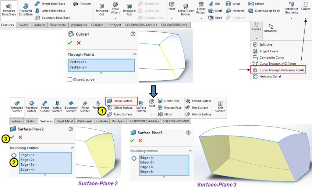
STEP 40
Create a straight curve between the resulted points on open area and close everything by 2 new Planar Surfaces as shown:
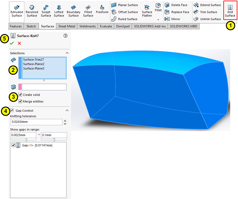
STEP 41
Knit all visible surfaces and also create a solid body:
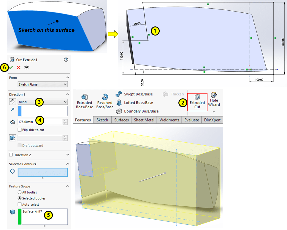
STEP 42
Select the Planar face, create the sketch as shown and remove the material with a Cut-Extrude feature:
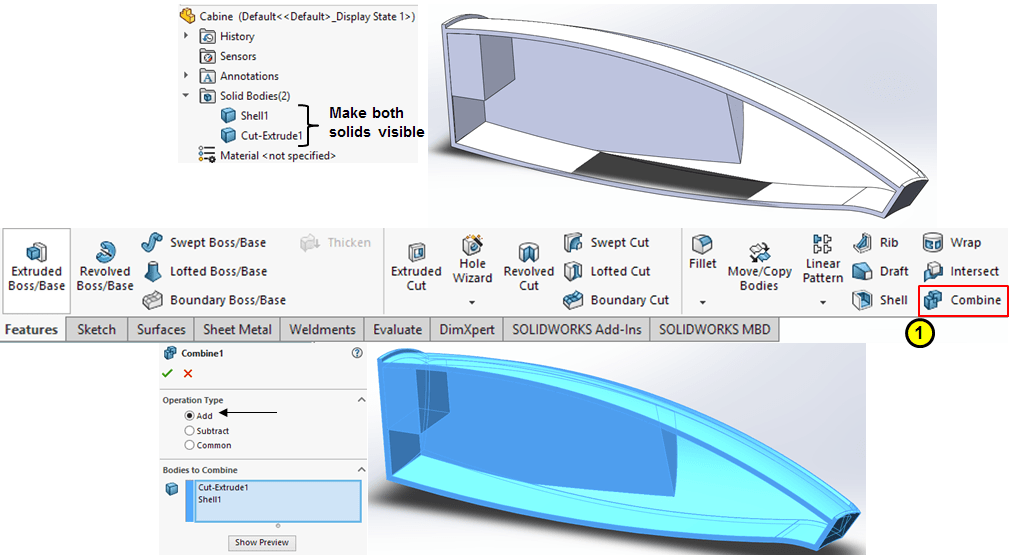
STEP 43
Now check the Solid Bodies box in model tree and make sure both bodies are visible. The click on Combine icon and let the 2 bodies join in a Add operation:
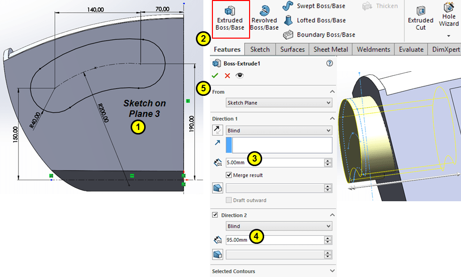
STEP 44
Create an 100mm (5mm+95mm) Extrude feature on the front face as shown:
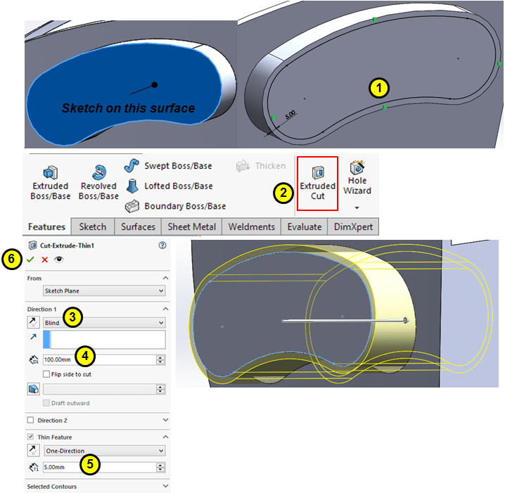
STEP 45
Using the planar surface from the previous Extrude feature, create an Extruded-Cut as shown:
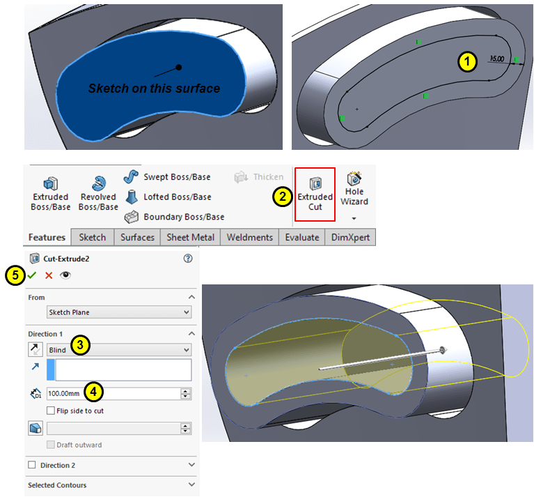
STEP 46
Create another Extruded-Cut as shown:
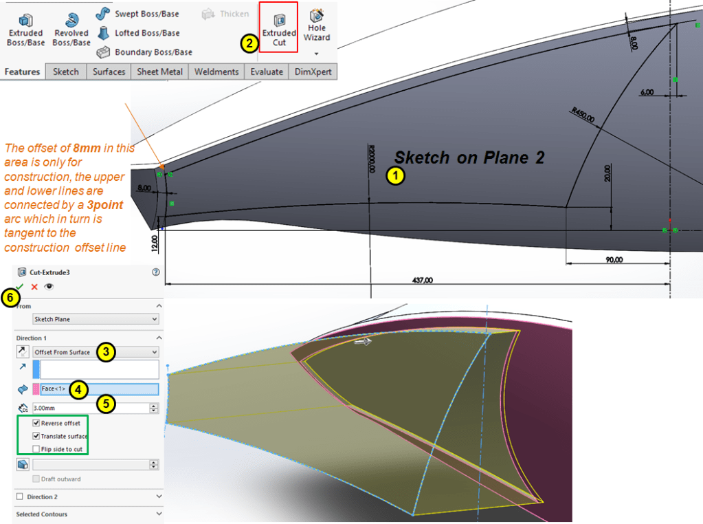
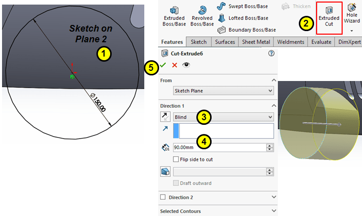
STEP 47
Draw the skech as shown on the Plane 2, then Cut-extrude it as shown:
STEP 48
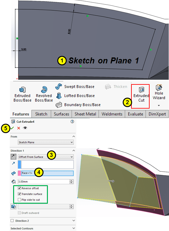
On the rear side use the Plane 1 to draw the sketch and create an Extruded-Cut similar with the prevoius one.
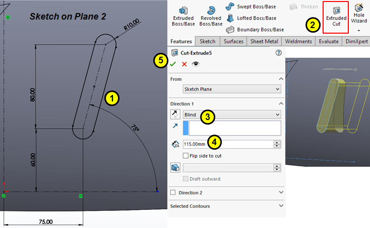
STEP 49
Create the extruded-cut from an oblong sketched on Plane 2:
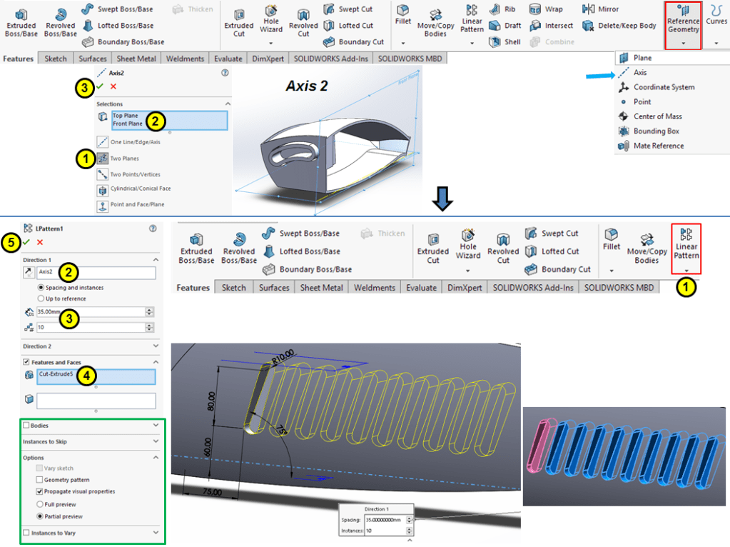
STEP 50
Before to Linearly pattern the oblong , you need to create a constuction axis beween the Top and Front plane, then pattern the previous extrude-cut 10 times along the axis 2.
STEP 51
Add another Extruded-Cut feature sketched on Plane 2:
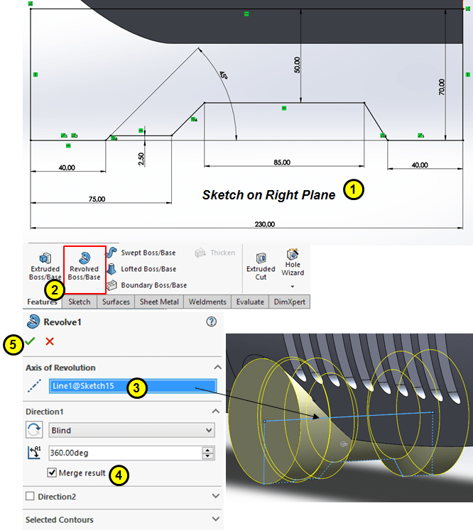
STEP 52
Draw the following sketch on the Right Plane and use it for a Revolved Boss as shown:
STEP 53
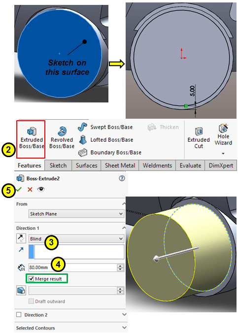
On the planar round face add an Extruded Boss of 80mm
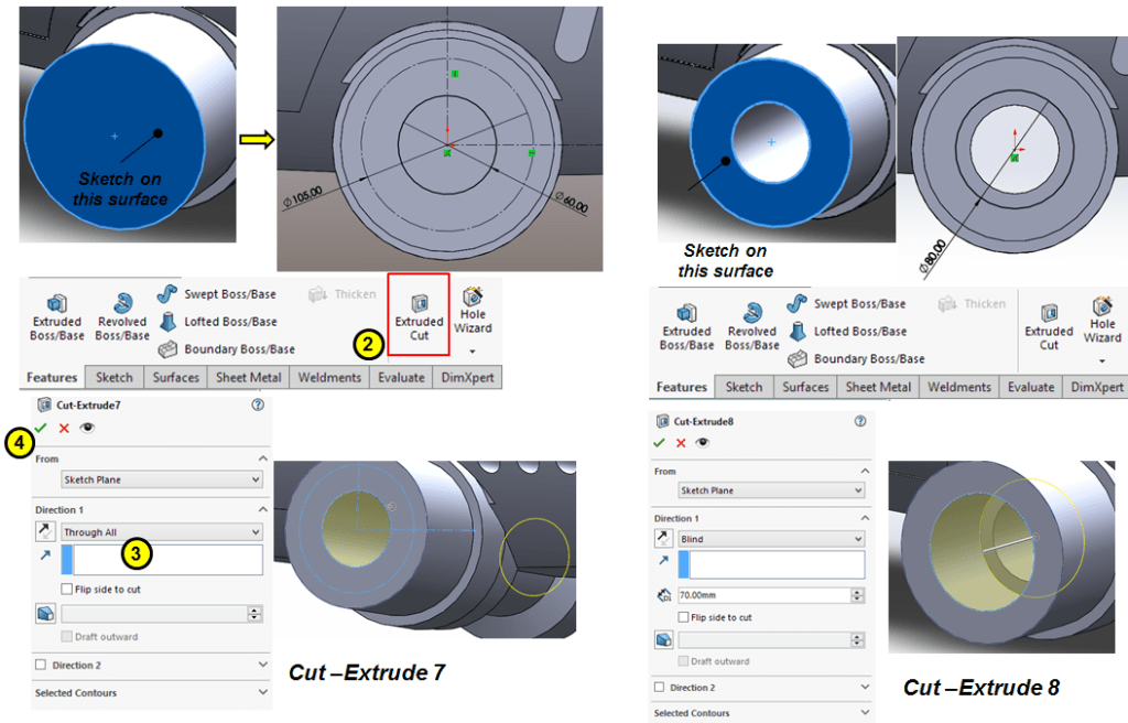
STEP 54
Continue to add 2 more Extruded-cuts on the planar side of the revolved boss as shown:
STEP 55
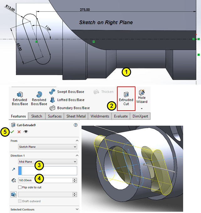
Create an oblong extruded-cut on the revolved boss as shown:
STEP 56
Create a threaded hole on the planar face of the revolved boss as follows:
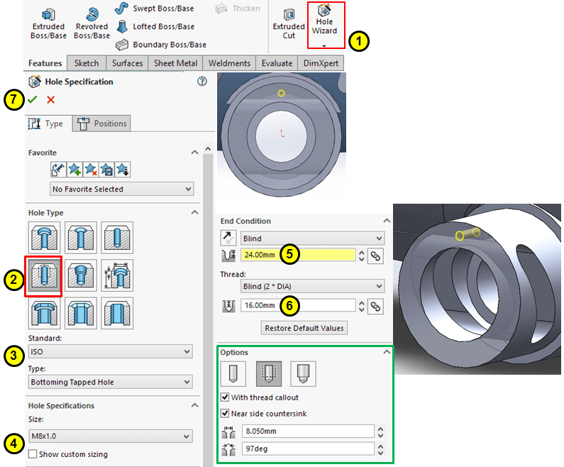
STEP 57
Pattern the threaded hole around the circular surface of the revolved boss:
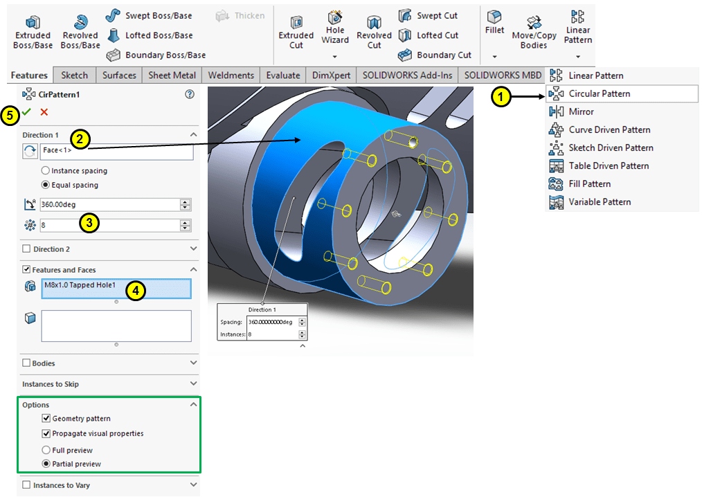
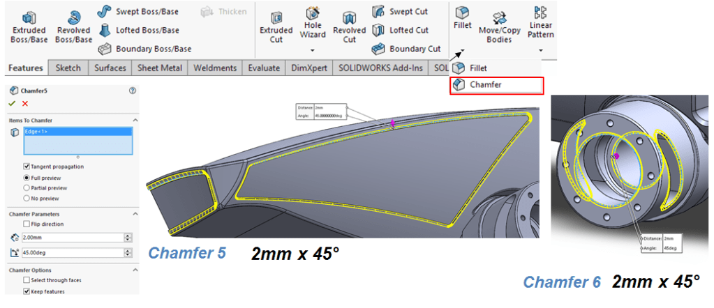
STEP 58
Add the first 2 chamfers as follows:
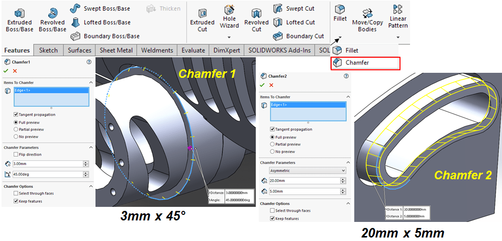
STEP 59
Continue to add the next 2 chamfers as shown:
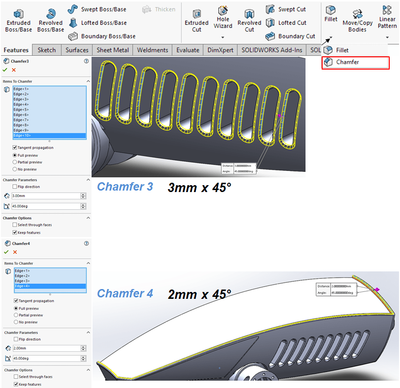
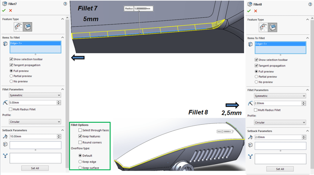
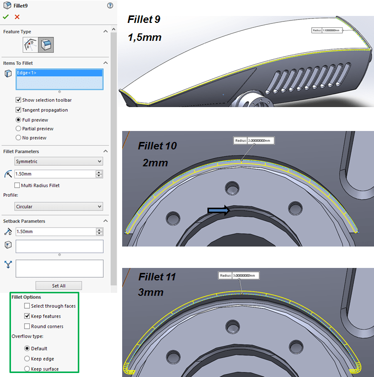
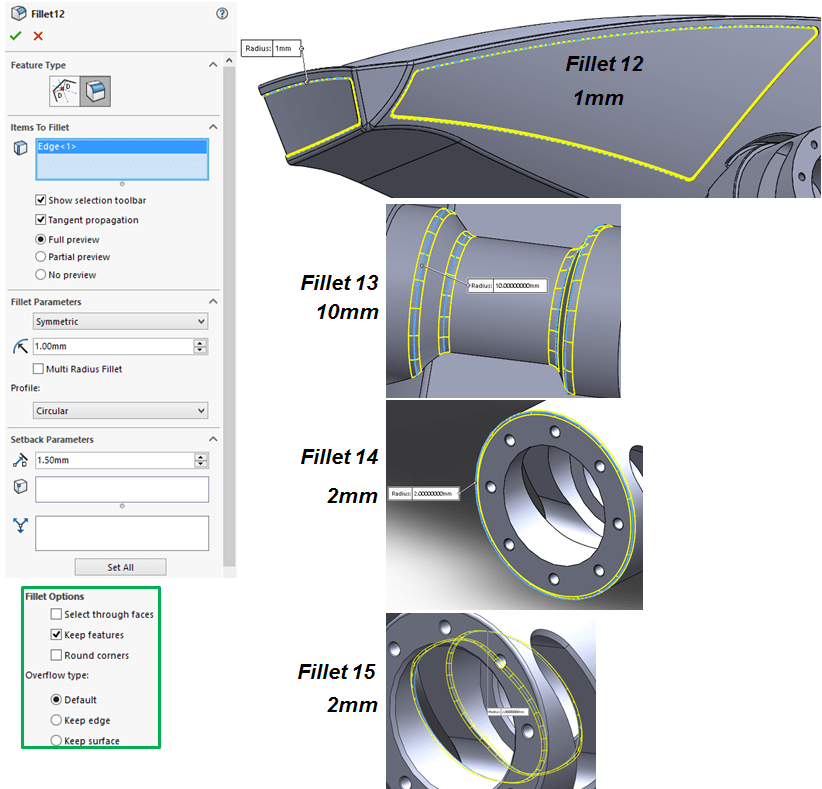
STEP 60
Add fillets as follows:
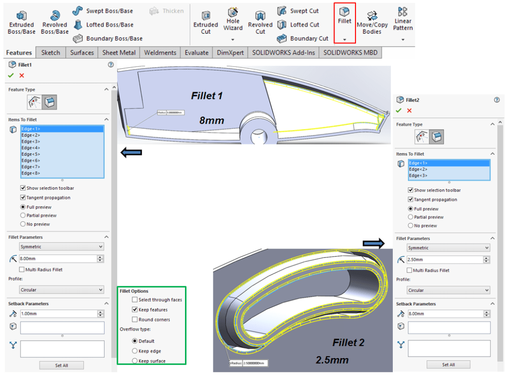
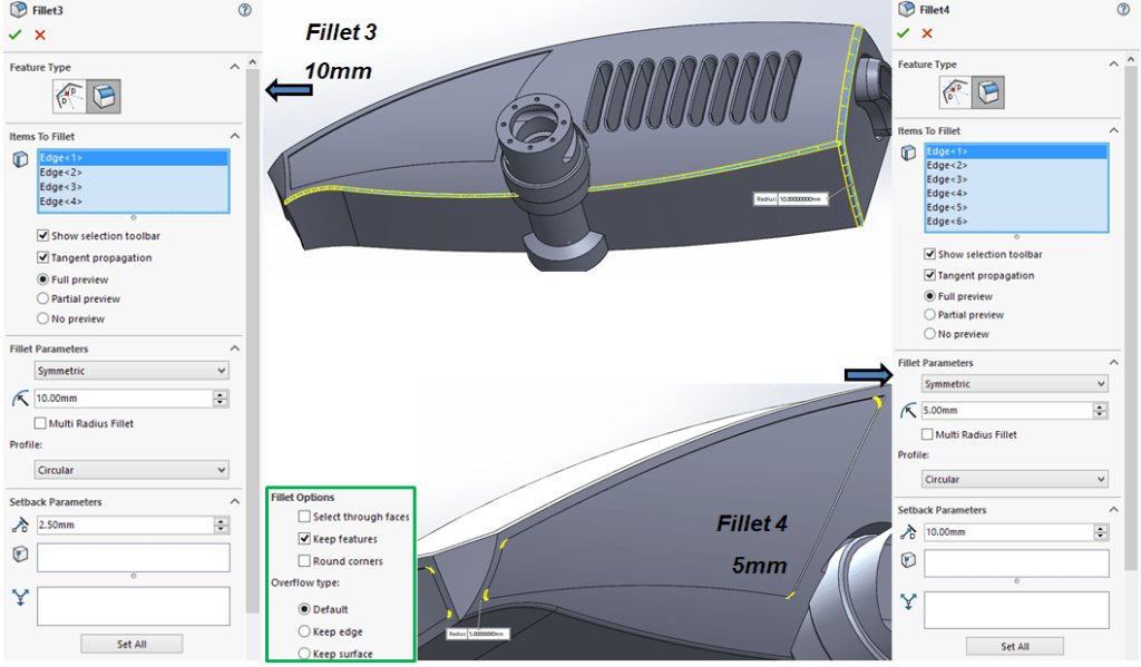
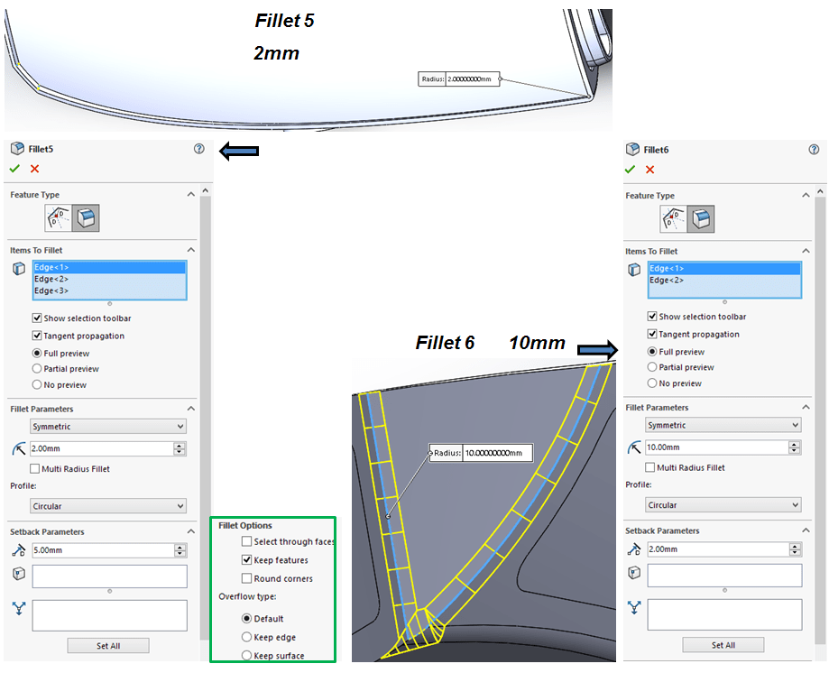
STEP 61
Add the last 2 chamfers:
STEP 62
Mirror the everything with the Front plane
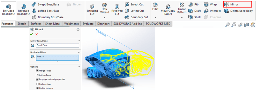
STEP 63
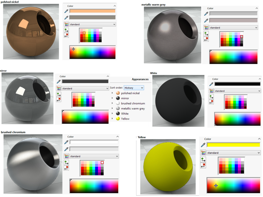
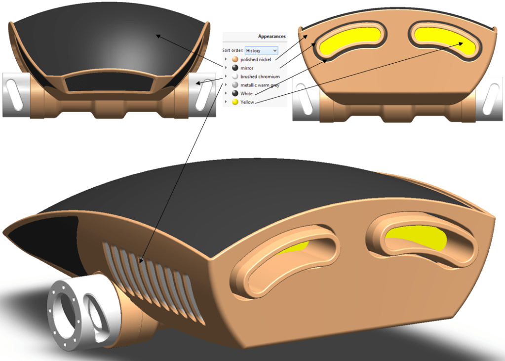
Add appearances, like for instance like the followings:
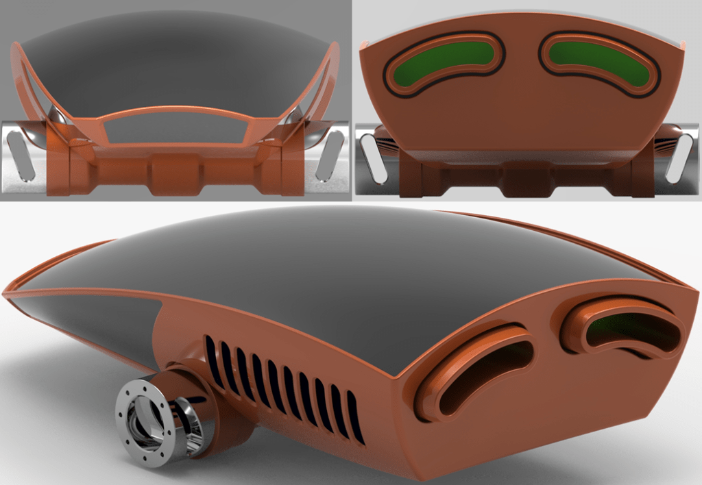
…with a better rendering in KeyShot the final part could look like this:
This design work is also available as video version on my YouTube channel as embedded below:

Leave a comment