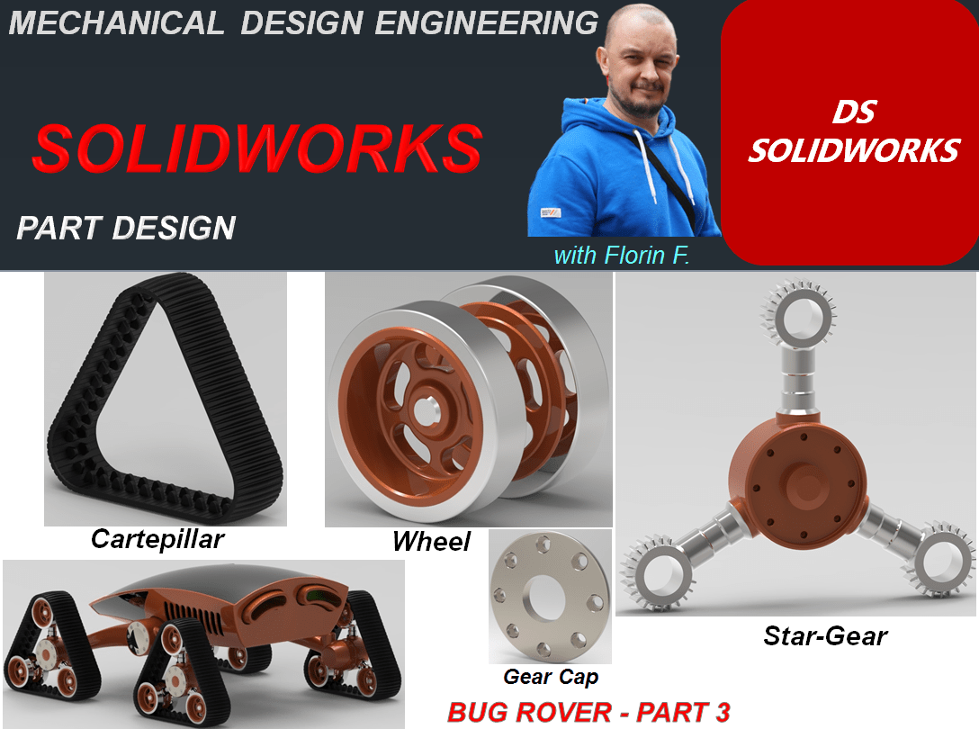
In this Part of Bug Rover design work, I’ll show you the 3 main components of the Carterpilar assembly. These are: The Star Gear, The Gear Cap, The Wheel and The Carterpillar. Let’s start:
THE STAR GEAR
STEP 1

Create a new part
STEP 2
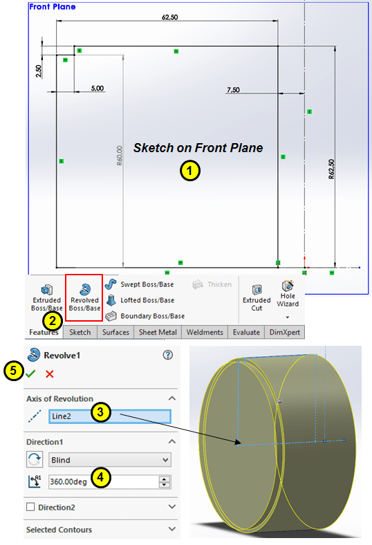
On Front plane draw the following sketch and revolve it as complete cylinder.
STEP 3
On Front plane sketch another profile which is perpendicular on the cylindrical surface of the previous feature. And create another revolved feature as shown:

STEP 4
Add a new datum plane as an offset from Right plane through the top point of the sketch from the vertically revolved feature:

STEP 5

On plane 1 sketch a circle of Ø65 and extrude it by the mid-plane with 36mm at 10°
STEP 6
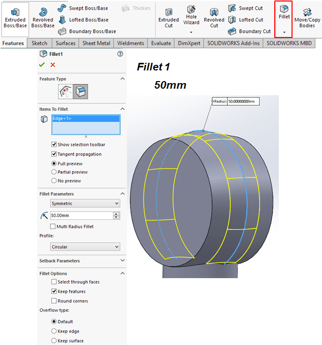
Add a fillet of 50mm on the mid-edge
STEP 7
Draw a sketch on Front plane and extrude it 2,5mm by mid-plane creating a sort of rib feature

STEP 8
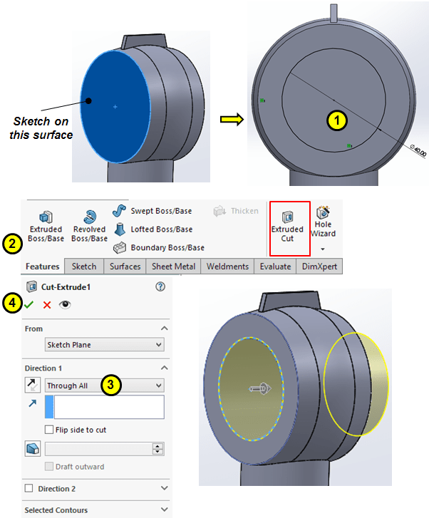
On the frontal planar side sketch a circle of Ø40 and cut-extrude it through all
STEP 9

Create a cut-extrude feature on the base cylinder as shown:
STEP 10
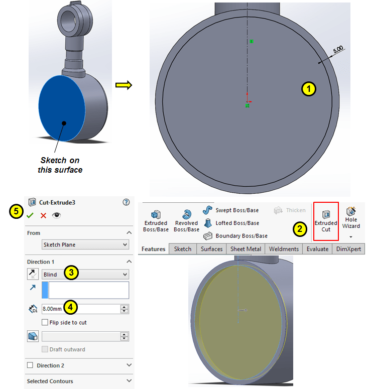
Remove material from the front side of the base cylinder with a cut-extrude of 8mm deep.
STEP 11

Create a revolved feature as as midle shaft on the base cylinder as shown:
STEP 12
Create a construction sketch on the planar face of the base cylinder, then create a threader hole of M8 as follows:

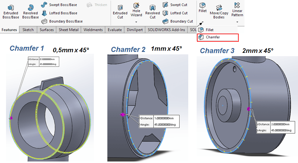
STEP 13
Add chamfers as follows:
STEP 14
Add fillets as follows:

STEP 15
Circular pattern the threaded hole around the outer surface of the base cylinder for 8 instances egually spaced:

STEP 16
Circular pattern of the rib from side cylinder for 24 instances as shown:

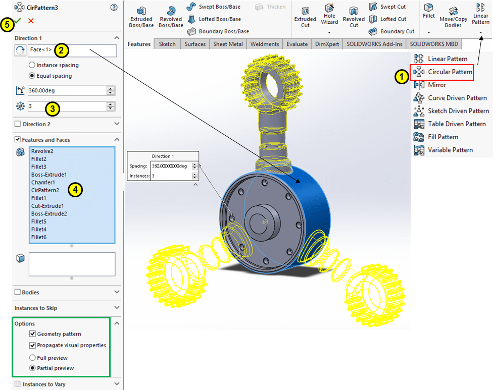
STEP 17
Circular Pattern the vertical cylinder and every additional features attached to it around the central cylinder for 3 instances as shown:
STEP 18
Add appearace:

..with a better rendering in KeyShot the final part could look like this:

THE GEAR CAP
STEP 1

Create a new part
STEP 2
Create the following sketch on Right Plane and revolve it 360°

STEP 3

On the planar surface draw a circle as shown and extrude it through all:
STEP 4
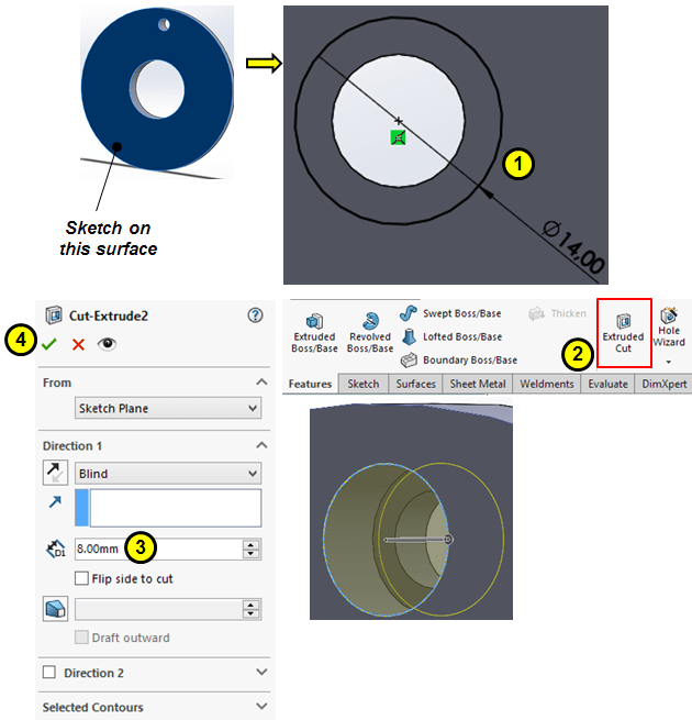
Create the 2nd extrude cut as shown:
STEP 5

Add a small chamfer of 0,5mmx45° on the counterbore edge
STEP 6
Pattern the last 3 features around the outer surface as shown:

STEP 7
Add 2 fillets as shown.
STEP 8

Add appearance

…with a better rendering in KeyShot the final part could look like this:
THE WHEEL
STEP 1

Create a new part
STEP 2
On front plane draw the following sketch and revove it into a complete cylinder

STEP 3
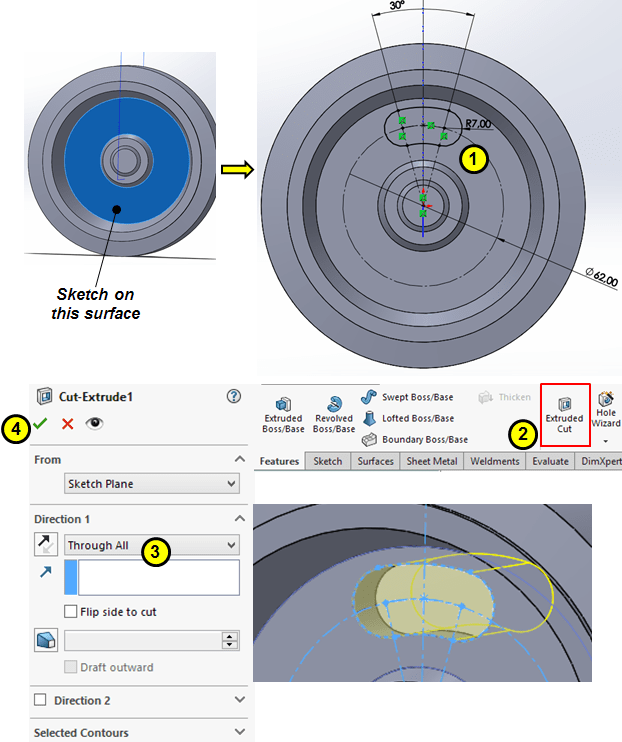
Sketch a centerpoint arc slot on the inner planar surface and cut-extrude it through all
STEP 4
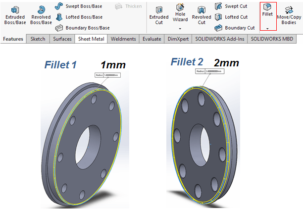
Add fillets and chamfer

STEP 5
Circular Pattern the slot cut-out and Fillet 2 around the outer cylindrical surface for 5 instances equally spaced:

STEP 6
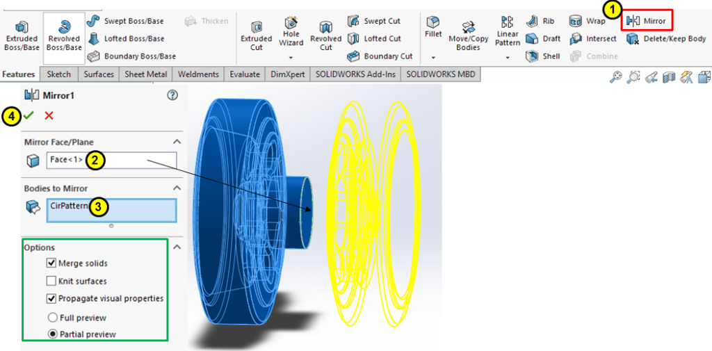
Apply mirror feature for the entire body as shown:
STEP 7
Create a Ddatum plane placed in the middle of part as shown:

STEP 8
Add appearance

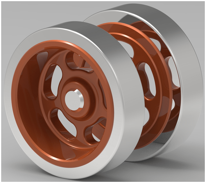
…with a better rendering in KeyShot the final part could look like this:
THE CARTERPILAR
STEP 1
Create a new part
STEP 2
Create the following sketch on the Front Plane and extrude it in 2 directions (60mm + 15mm)

STEP 3
Apply chamfers and fillets as follows:

STEP 4
Create a small groove on the top outer surface as an extruded-cut:
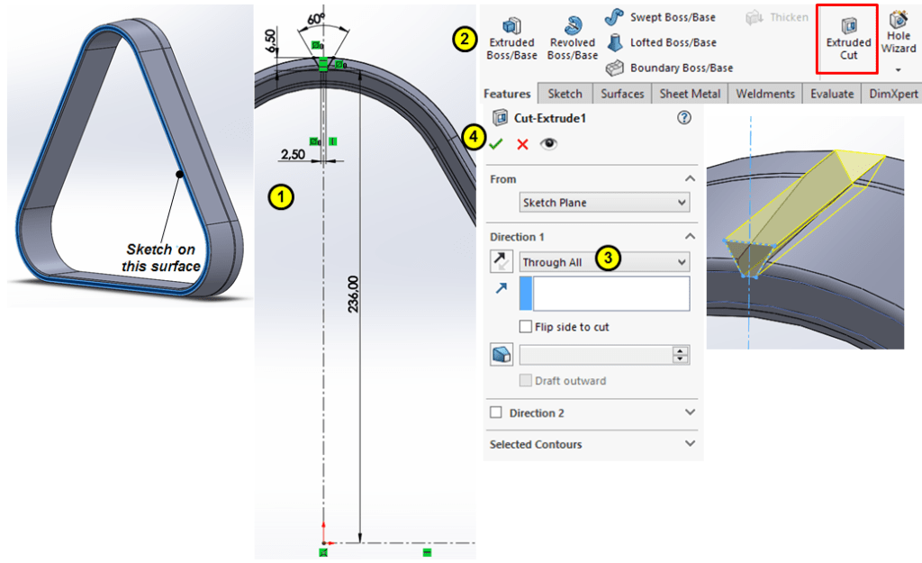
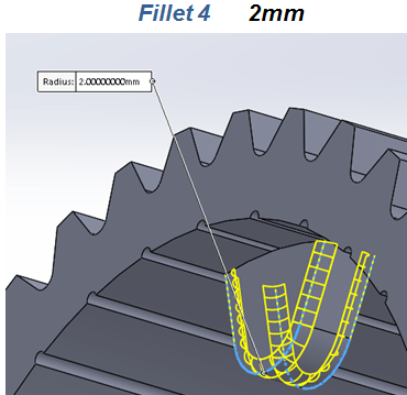
STEP 5
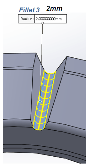
Add a fillet of 2 mm at the groove’s bottom
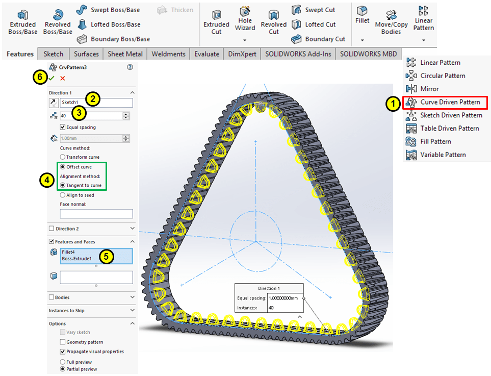
STEP 6
Convert the outer edges into a sketch on the front surface and use that curve to pattern the groove as Curve Driven of 100 instances egually spaced, as shown:

STEP 7
Similarly create another groove on the inner surface also an an Extruded-cut:
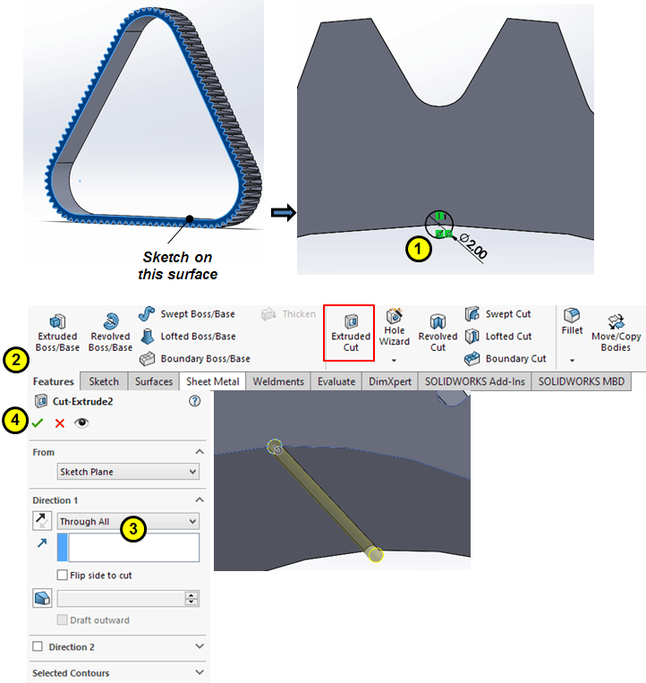
STEP 8
For the inner groove use the 1st Sketch created at STEP 2 as guide to create a Curve Driven Pattern of 100 instances on inner surface as shown:

STEP 9
Create a new datum plane as an 20mm offset from the frontal surface:

STEP 10

Use the Plane 1 to create a new feature as an Extruded Boss on the top area:
STEP 11
Add a fillet of 2mm on side edges:
STEP 12
Use the 1st Sketch created at STEP 2 as guide to create a Curve Driven Pattern of 40 instances with the previous extruded boss on inner surface as shown:
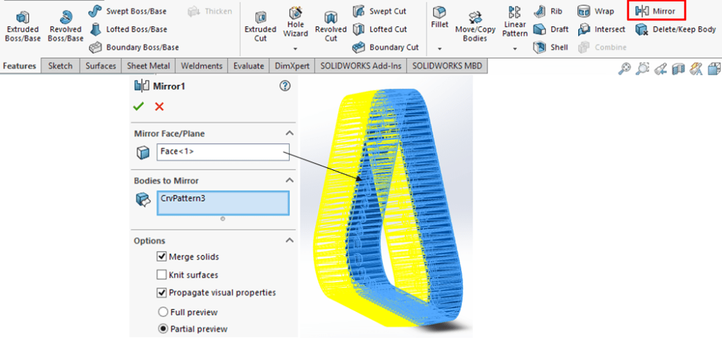
STEP 13
Apply the Mirror feature on the frontal surface:
STEP 14
Apply appearance:

…with a better rendering in KeyShot the final part could look like this:

This design work is also available as video version on my YouTube channel as embedded below:

Leave a comment