
As we’ve already seen in the previous posts, The Bug Rover is made of various components. In this post we’ll put everything together in the final product. But before to create the final assembly, let’s create first the Sub-Assembly called Carterpilar which will be later used as multiple instances for the final assembly. Let’s start:
THE CARTERPILAR ASSEMBLY
STEP 1
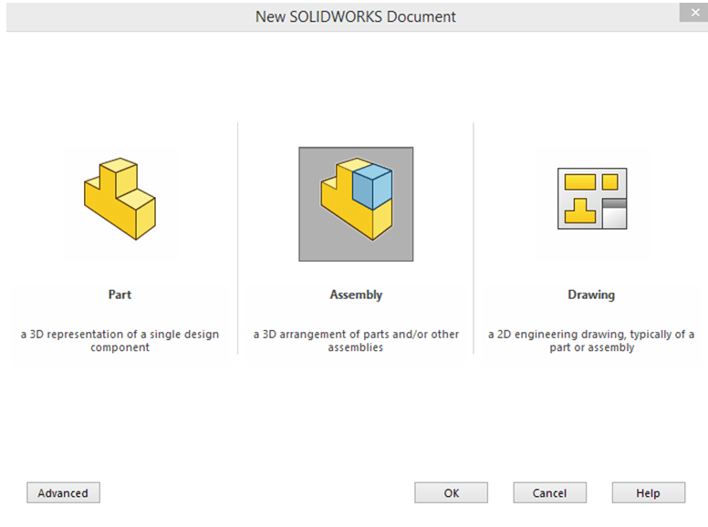
Create a new assembly
STEP 2
Right after new assembly file is created, SOLIDWORKS will ask you to Begin the Assembly by adding components. Here you just have to browse for the file called Star-Gear in the project folder and click Open then again OK to confirm that the part has been added.

STEP 3
In Assembly Mode, click on Insert Components and continue to add new components in the same way. The next one being the part called Gear-Cap. Then Click on Mate icon and enter the 3 constraints as shown below:

STEP 4
Often times Standard components are used too. But these don’t have to be designed again frim scratch. The Solidworks Design Library contains a variety of such components according to differents international standards so that they are available and can be anytime used. This saves a lot of time and you don’t have to worry designing these components. Just find in the library what you need and use it. In my case here, I’ve chosen for a Socket Head Cap Screw acc. to ISO 4762. The browsing steps in the Design Library are as follows:
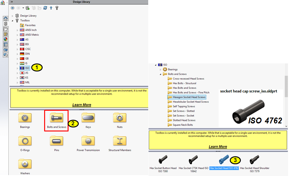
… then choose for and M8 x12 Screw and apply the placement in the 8 holes as shown:

STEP 5
Continue to add the next componet, which is The Wheel. For Wheel only 2 constraints are needed.

STEP 6
You can add the other 2 wheels in the same fashion like the 1st one, but a faster option now is to just pattern the already existing one. For this click on the small black arrow pointing downwards under the Linear Component Pattern icon and then click on Circular Component Pattern.
Use the central cylindrical surface from the Star Gear part as rotation direction and add 2 more wheels in the assembly as follows:

STEP 7
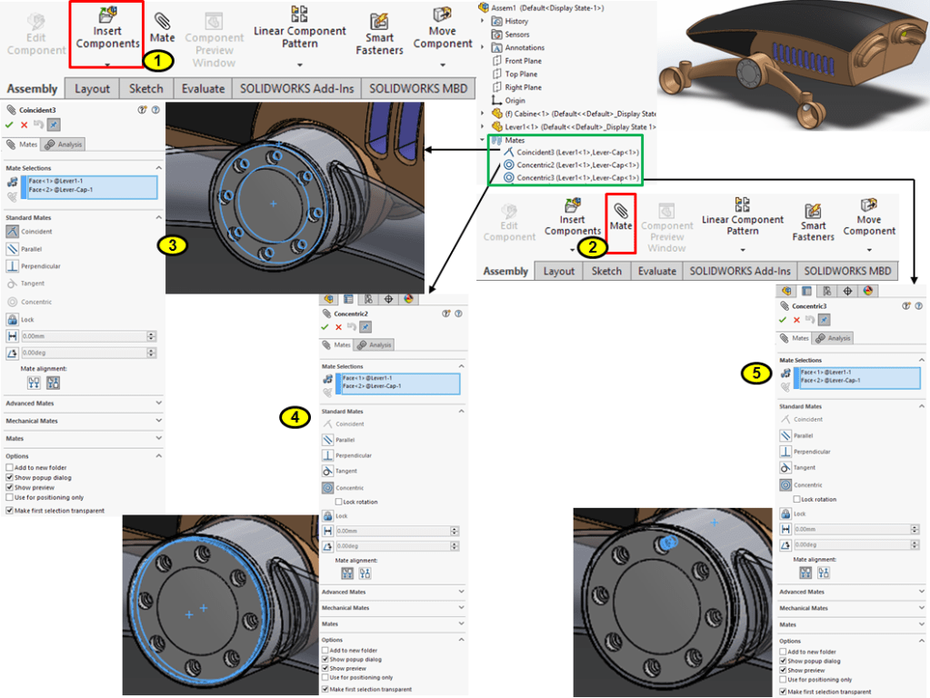
Finally add the Carterpilar part and enter its 3 constraints as follows:


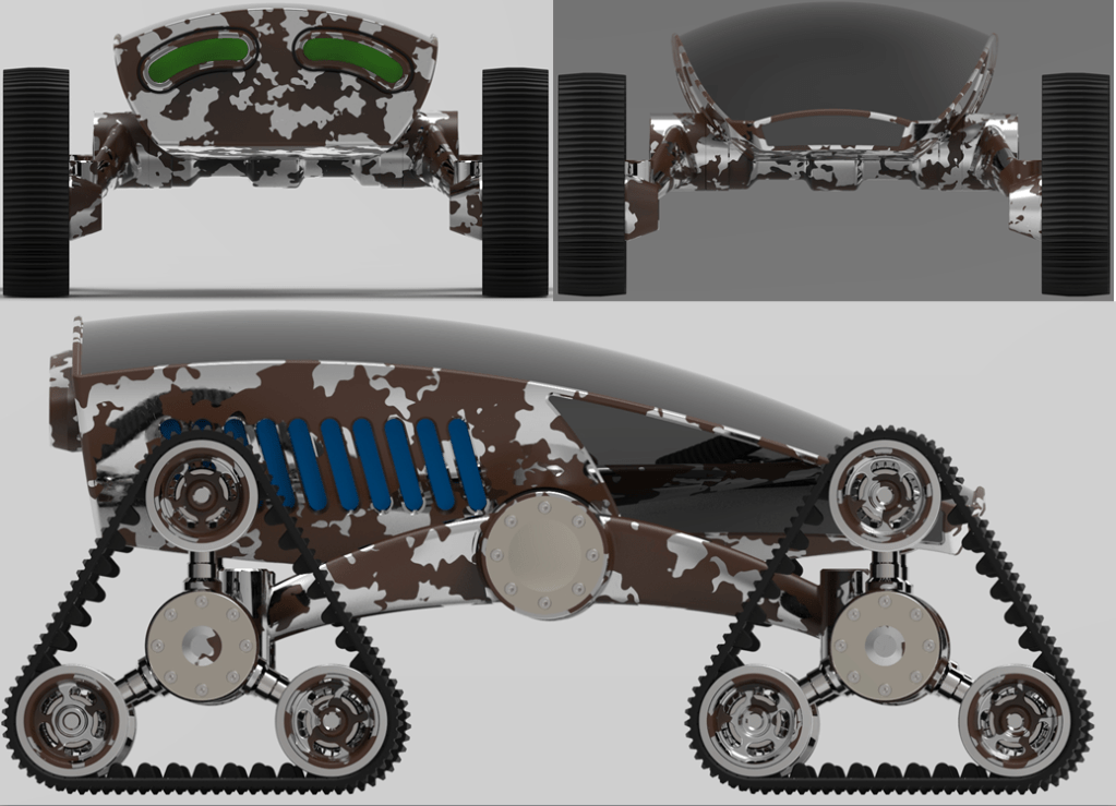
After rendering with Keyshot, the Carterpilar Sub-Assembly looks like this:

Now finally let’s create the BUG ROVER Product.
THE BUG ROVER ASSEMBLY
STEP 1

Create a new assembly
STEP 2
Like done for the previous sub-assembly, here again SolidWorks asks you to begin the assembly by adding comopnents. This time, from the same project folder pick the part called Cabine.

STEP 3
Add the next component Lever and enter its 3 constrainst as follows:

STEP 4
Add the Lever cap
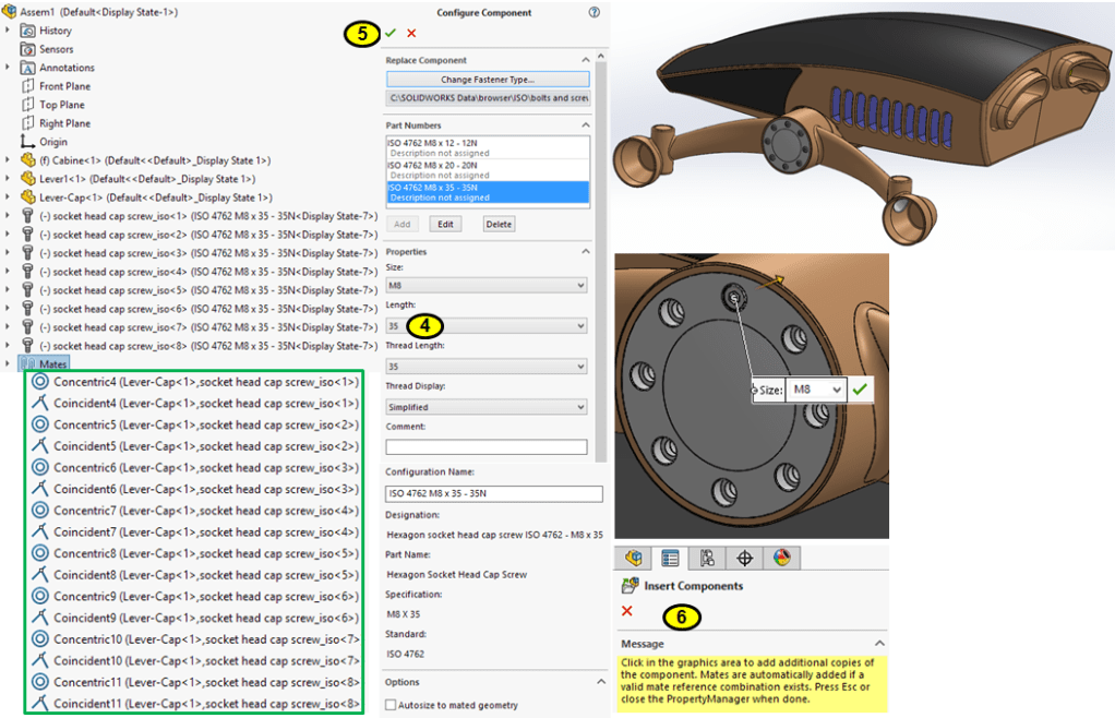
STEP 5
From Solidworks Design Library, add the ISO 4762 Socket head Cap Screw M8x 35
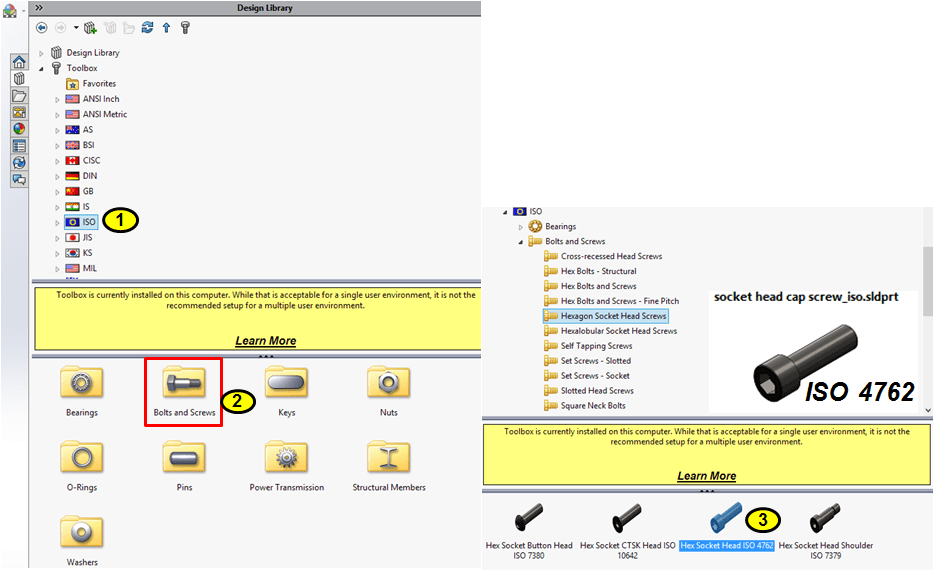
… continue to place screwes in each of the 8 holes
STEP 6
Add the Carterpilar Sub-Assembly
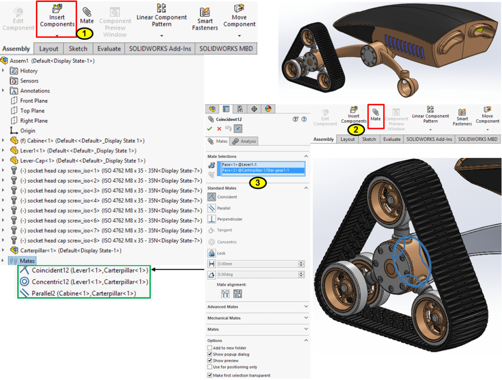

STEP 7
Apply Linear Pattern at 750mm along the Cabine’s Right Plane for the Carterpilar sub-assembly

STEP 8

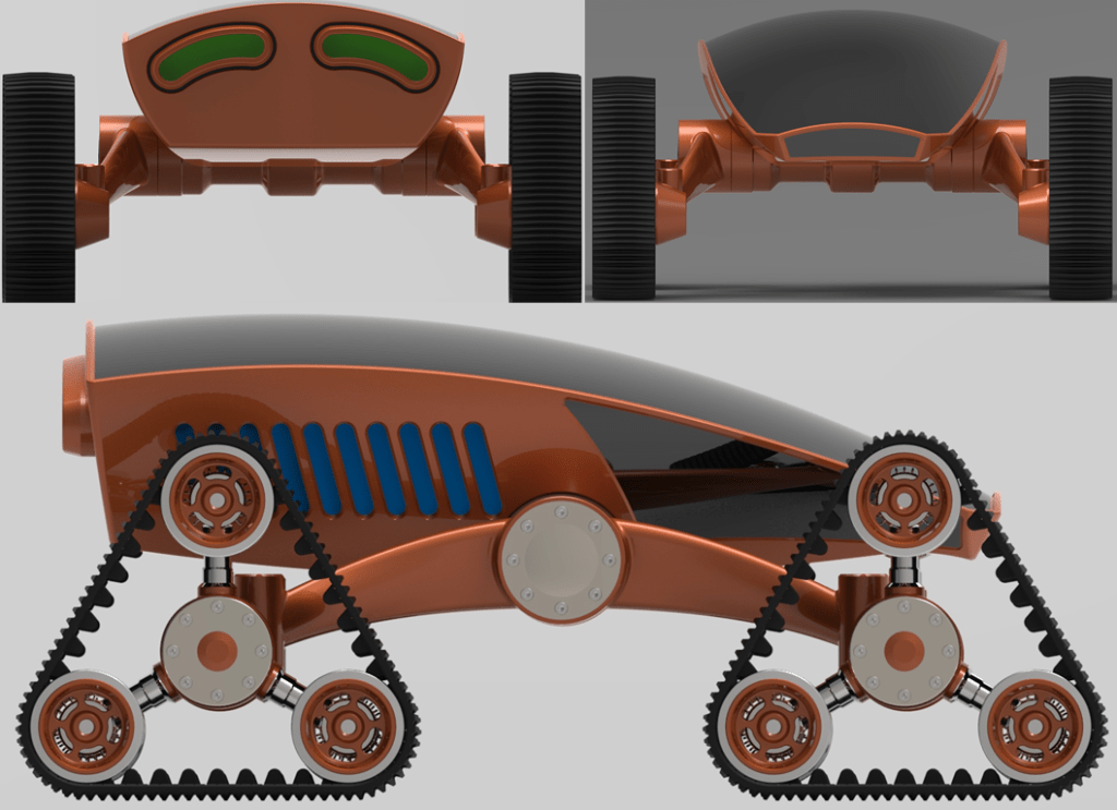
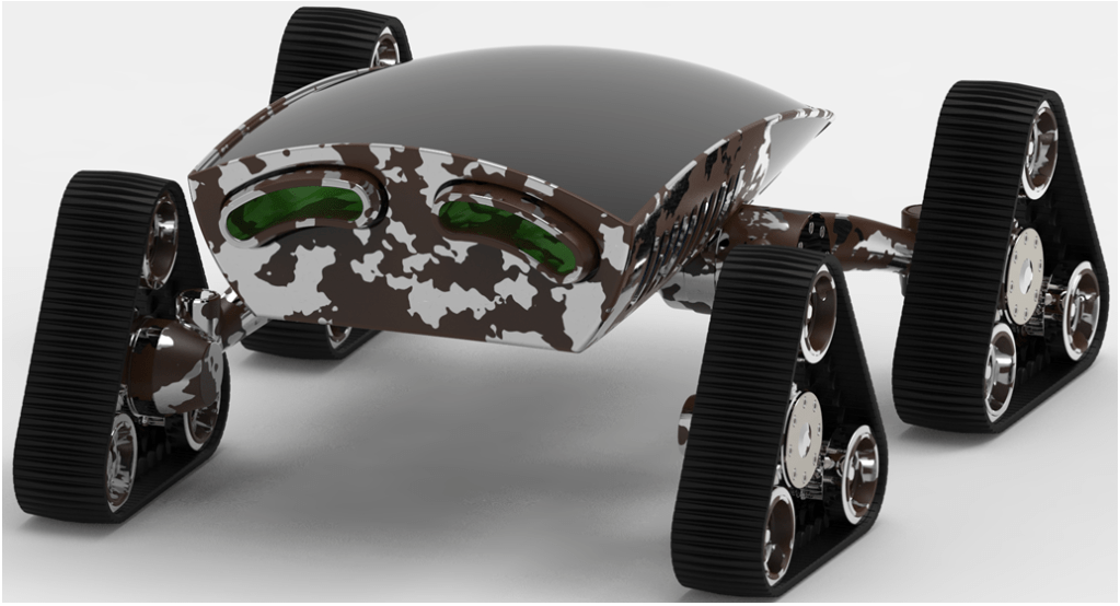
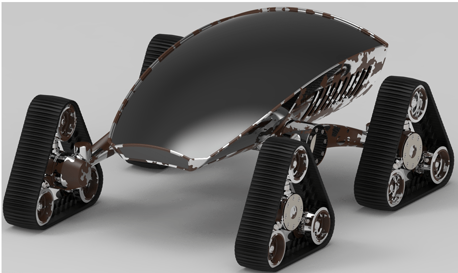
… appliyng the Keyshot rendering the Bug Rover design in ready:


This design work is also available as video version on my YouTube channel as embedded below:

Leave a comment