Runout is a very effective geometric tolerance which can be applied on any rotationally symmetrical parts. Depending on functional requirements, RunOut tolerance can be either measured on each individual point distributed arbitrary along the tolerated circular element which in this case is specifies as Circular RunOut tolerance. Or can be measured over the entire surface of the circular element which then is specified as Total RunOut tolerance. Generally most of charactereistics valid for Circular Runout are applicable to Total Runout. However there are some specifics for each and in this article we’ll focus on TOTAL RUNOUT Tolerance.
Description
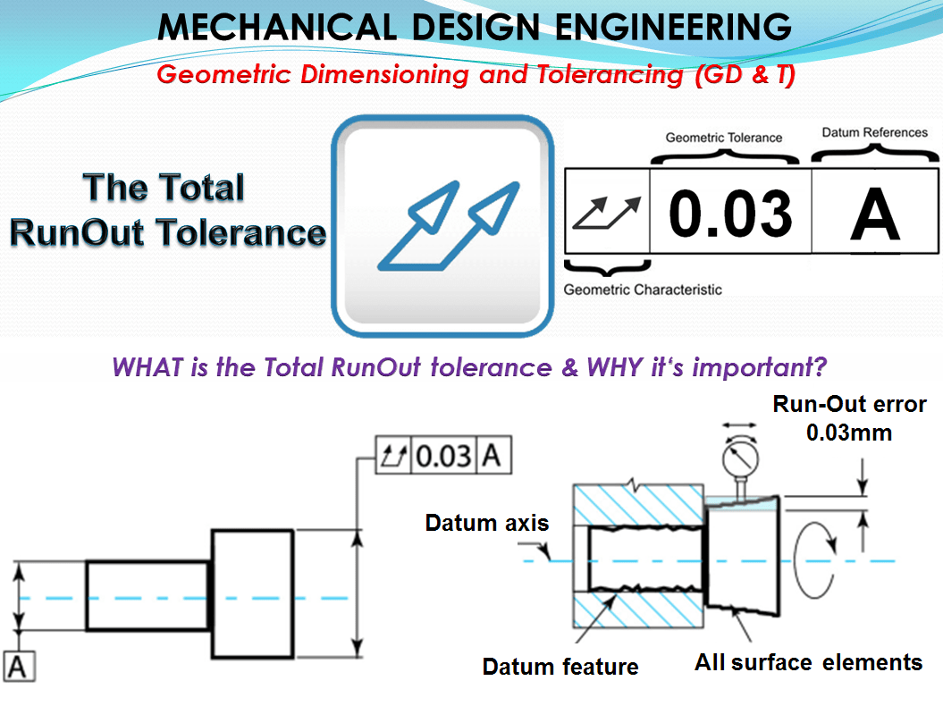
Definition: Total Runout is how much one entire feature or surface varies with respect to a datum when the part is rotated 360° around the datum axis. Total runout controls both the amount of variation in the surface as the part is rotated, and the amount of variation in the axial dimension. Both radial variation and axial variation are measured and held within the tolerance. Total Runout is usually called on a part that is rotated about an axis where the entire surface is critical to be in spec.
The total run-out was added to the system of form and position tolerance according to DIN EN ISO 1101 only later due to the metrological development. It has prevailed in practice because it has several important functional type of tolerances on rotating parts which can be checked with a single measurement; however, in the case of mechanical measurement, it requires the appropriate equipment.
Symbol: The Symbol for Total Run-Out tolerance is 2 slanting connected arrows pointing upwards to the right, representing the displacement of the measurement device.

The Tolerance call out: – The feature control frame includes the total runout symbol and tolerance value followed by up to 1 or 2 datum references.
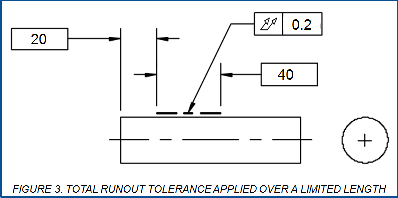
Since a runout tolerance applies to surface elements, it sometimes makes sense to limit the control to a limited portion of a surface, over a limited length. A designer can do this easily by applying a chain line as shown in figure 3. In such cases, draw a heavy chain line adjacent to the surface, basically dimensioned for length and location as necessary. The Total Runout tolerance applies only within the limits indicated by the chain line.
Worst Case Boundaries – Instead of troweling on feature control frames for form and location, a clever designer can often simplify requirements by using a few well-thought-out runout tolerances to control combinations of relationships. A circular runout or total runout tolerance applied to an internal or external diameter feature yields a worst case inner boundary equal in size to the feature’s small-limit size minus the value of its runout
tolerance and a worst case outer boundary equal in size to the feature’s large-limit size plus the value of its runout tolerance. The inner or outer boundary can be exploited to protect a secondary requirement for clearance without using a separate positional tolerance.
Total runout and included tolerances: The tolerance zone (as shown in the example 2 Figure 7a below) includes multiple types of tolerance:
RULE #1 : The Total runout tolerance tTR includes:
• The cylindricity of the entire surface;
• the roundness of each cross-section;
• the straightness of all surface lines and the nominal axis;
• the parallelism of the surface lines to the axis and to each other (the latter with the double tolerance value);
• the coaxiality of the tolerated element (with a factor U”” 1.2, see Rule #4 and Rule #5 from the article about Circular Runout).
All individual deviations can reach the value tTR at most, except for the parallelism of the opposing surface lines (limit deviation 2tTR) and the concentricity (Limit value U*tTR/2, with the reservations according to Rules #4 and Rule #5 from the article about Circular Runout).
Total runout in any direction: The total runout tolerance is also conceivable to be applied other surfaces, for instance on a cone. However the standard does not provide that, for good reason. For a mechanical measurement of a cone, the appropriate setup would have to available; but that is usually not the case. When it comes to tolerate a cone in general, then the surface profile tolerance does it better. A total runout cone tolerance would correspond to the illustration in Figure 4d see the article about Surface Profile tolerance. However, those sketches from a to e (see Figure 4 in Surface Profile tolerance article) contain additional options that the total runout tolerance does not offer.
Tolerance Zone
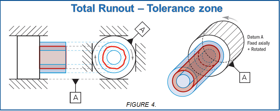
For Total Runout the tolerance zone is a 3-Dimensional cylindrical zone that surrounds a referenced surface that is directly derived from either the datum surface or the axis. All points along the surface must fall within this zone when the part is rotated at all times, as illustrated in figure 4.
When is the Total RunOut Tolerance used
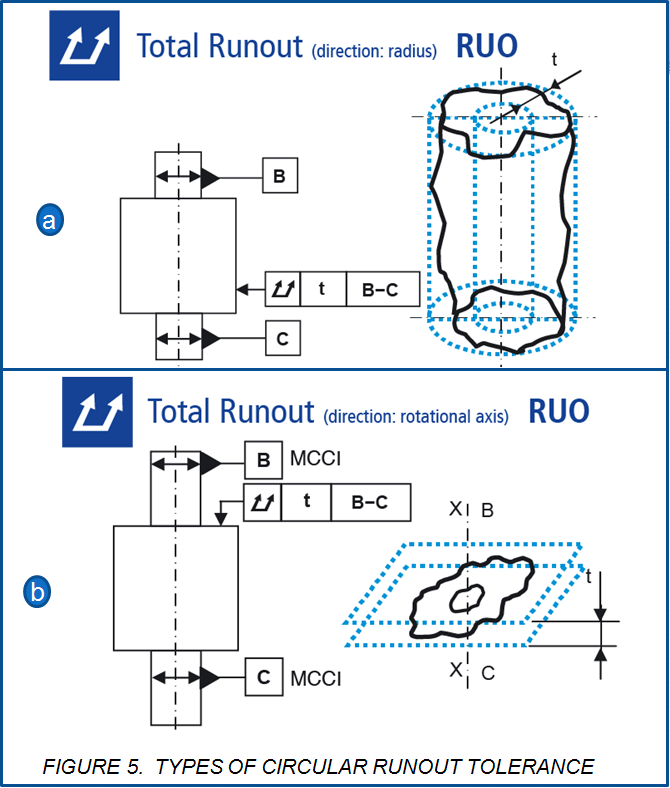
Total runout is much less common than circular runout due to the tight constraint it puts on an entire part surface. However it is still a fairly common symbol in GD&T due to its functional effect of preventing vibration and oscillation. It is very effective at preventing surface taper of a cylinder. Any time a part rotates and has a large amount of surface contact, total runout may be required. Things like large pump shafts, transmission shafts, and complex gears all are cases where total runout is used.Similar with Circular Runout, the Total Runout can be measured in 2 ways as illustrated in figure 5, namely:
- Total Runout – Radial,
- Total Runout – Axial
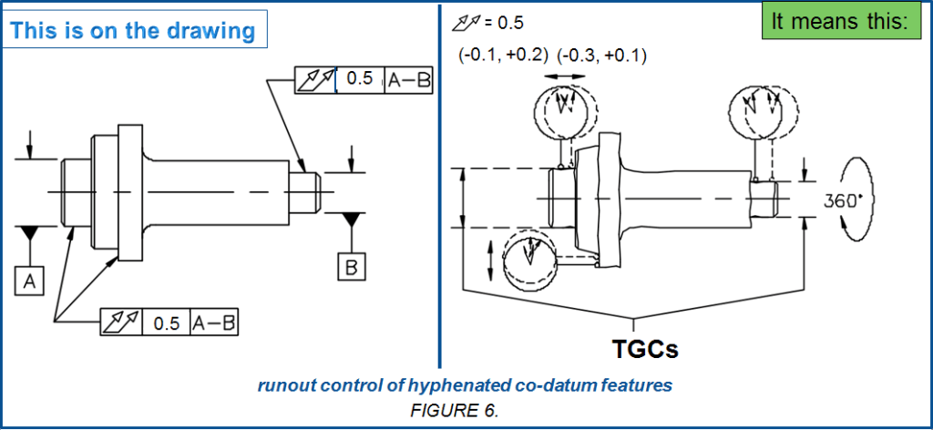
In the feature control frame, the datum reference letters are placed in a single box, separated by a hyphen. The hyphenated co-datum features work as a team. Neither co-datum feature has precedence over the other. We can’t assume the 2 journals will be made perfectly coaxial. To get a decent datum axis from them, we should add a runout tolerance for each journal, referencing the common datum axis they establish. As shown in example 1 figure 6 this is one of the few circumstances where referencing a feature as a datum in its own feature control frame is acceptable.
Therefore runout tolerances are especially suited to parts that revolve about a datum axis in assembly, and where alignments and dynamic balance are critical. Circular runout tolerance is often ideal for O-ring groove diameters, but watch out for surfaces inaccessible to an indicator tip. This might be an internal O-ring groove where the cylinder bore is the datum.
Q: How can an inspector spin the part about that bore and get his indicator tip into the groove at the same time?
A: As I said, there are other inspection methods, but a designer should always keep one eye on practicality. The following equations pertain to the controls imposed by circularity, cylindricity, concentricity, circular runout, and total runout when applied to a revolute or cylindrical feature.
CIRCULARITY + CONCENTRICITY = CIRCULAR RUNOUT
CYLINDRICITY + CONCENTRICITY = TOTAL RUNOUT
Remember that FIM is relatively simple to measure and reflects the combination of out-of-roundness and eccentricity. It’s quite complex to differentiate between these two constituent variations. That means checking circularity or concentricity apart from the other requires more sophisticated and elaborate techniques. Of course, there are cases where the design requires tight control of one (say, circularity); to impose the same tolerance for the other (concentricity) would significantly complicate manufacturing. However, if this won’t be a problem, use a runout tolerance.
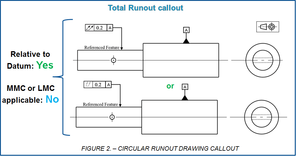
A runout tolerance applies directly to surface elements. That distinguishes it from a positional tolerance RFS that controls only the coaxiality of the feature’s actual mating envelope. Positional tolerancing provides no form control for the surface. While the positional tolerance coaxiality control is similar to that for runout tolerance, the positional tolerance is modifiable to MMC or LMC. Thus, where tolerance interaction is desirable and size limits will adequately control form, consider a positional tolerance instead of a runout tolerance.
Application of the total run-out tolerance: The function of many components, especially in power train technology requires that both the cylindricity and the concentricity deviations to remain small. Both can hardly be checked individually with mechanical measuring equipment (see the articles about cylindricity and concentricity). Yet with the total runout tolerance, however, they are recorded in a single measurement process (if a relevant measuring device is available). However, this advantage becomes irrelevant using a measuring device.
On the other hand, the nominal surface can exaust the total runout tolerance in various ways (see rule 2-56). For instance, the entire tolerance amount could be used as circularity deviation or as deflection or as axis misalignment position. Exceeding the tolerance also doesn’t allow to draw any direct conclusions about the cause and about possible corrections of the manufacturing process. With the advance of computer-aided measurement technology,
the importance of the total runout tolerance decreases in favor of individual details such as concentricity and cylindricity, which can be better adapted to the functional requirements. If we stay with the total runout tolerance, there is of course the possibility depending on the functional requirements,to enter an additional tolerance (e.g. circularity) with a smaller tolerance value than tTR. Let’s see some frequent examples:
Example 1: Total Runout control of hyphenated co-datum features
Total Runout is the greater level of runout control. Its tolerance applies to the FIM (“Full Indicator Movement.”) while the indicator sweeps over the entire controlled surface. Rather than each circular element being evaluated separately, the Total Runout FIM encompasses the highest and lowest of all readings obtained at all circles. For a nominally cylindrical feature, the indicator’s body shall be swept parallel to the datum axis, covering the entire length of the controlled feature, as the part is spun 360° about the datum axis. As shown in Figure 6, any taper or hourglass shape in the controlled feature will increase the FIM.
For a nominally flat face perpendicular to the datum axis, the indicator’s body shall be swept in a line perpendicular to the datum axis, covering the entire breadth of the controlled feature. Any conicity, wobble, or deviations from flatness in the controlled feature increase the FIM. The control imposed by this type of total runout tolerance is identical to that of an equal perpendicularity tolerance with an RFS (Regardless of Feature Size) datum reference.
Example 2: Standardized (DIN EN ISO 1101) Total Runout tolerances -radial and axial
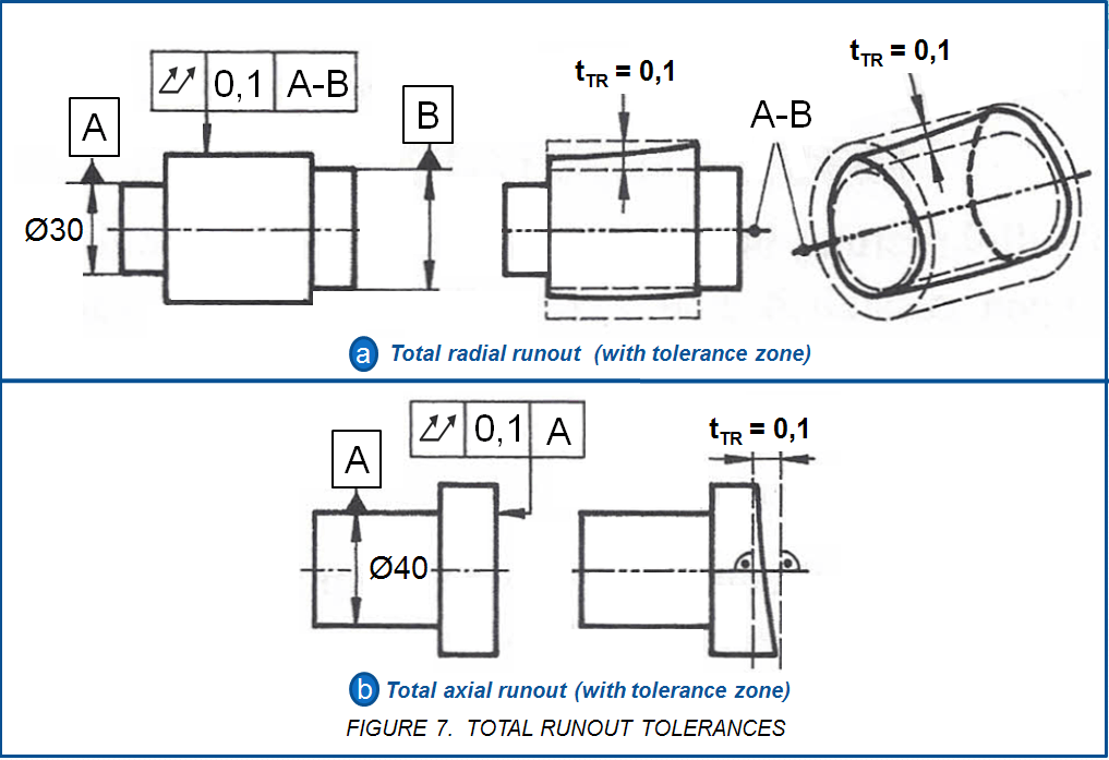
Figure 7a) – Total radial run-out: The dial gauge will move during rotation of the workpiece, parallel to the reference axis. The tip of the probe may move radially by the amount of the total running tolerance tTR. The tolerance zone is therefore initially an axis-parallel strip of width of tTR = 0.1 mm over the entire length of the tolerated element. As a result of the rotation, this becomes the space between 2 coaxial circular cylinders, which have the radial distance tTR, but their diameter is not fixed. This must include the entire tolerated area. This tolerance zone has the same shape as that of cylindricity (see the article about cylindricity), however bound to the reference axis.
Figure 7b) – Total axial run-out: The measuring device is guided perpendicular to the reference axis over the entire face. The strip of width tTR becomes the delimitation of the tolerance zone to 2 planes at a distance tTR, perpendicular to the axis. This tolerance zone is identical to that of perpendicularity (see the article about perpendicularity) with the same reference axis. This is is the rare case where two different tolerance types have identical tolerance zones, namely the total axial runout and perpendicularity. In both the flatness is included. The perpendicularity specification is more general and also easier to understand. We would therefore generally prefer them and only enter the total axial runout where this measuring method is actually used. On a measuring equipment in both cases runs same program.
Example 3: Rotating axle
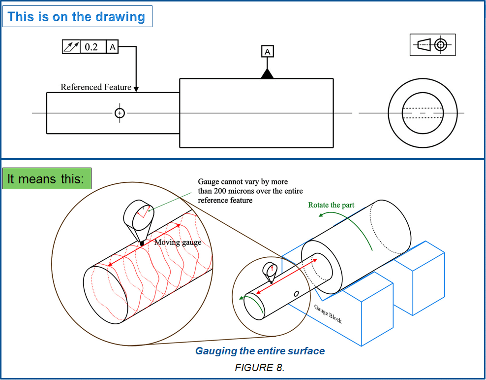
In Figure 8 an axle is normally under high stress and needs to fit evenly in a bushing (not shown). If the referenced surface does not make even, stable contact with the housing bushings the axle will wear unevenly leading to eventual failure. Surface ‘A’(datum) is controlled with a roller bearing and should be axially aligned with the reference surface. Total Runout is called in the same way as Circular Runout. Similar to Circular Runout, the Total Runout allows the final specification or condition of the part to be called out, thus controlling how the part reacts when it is rotated. The gauge to check this part for total runout would also be nearly identical as the normal runout gauge. The only difference would be that if you moved the gauge up and down the part, or had multiple gauges all fixed to each other, the total gauge indication along the entire surface could not be out.
NOTE: Circular and Total Runout can sometimes be used interchangeably to accomplish the same functional goal – Check out my article on Circular Runout for information on how a cross-section is checked as opposed to an entire surface.
Gauging / Measurement
The test procedure differs from that of the circular runout in one point acc. to the following rule:
Total Runout Measurement:= While the tolerated feature rotates around the datum axis, the measuring device is gradually moved over the entire tolerated area. The overall difference in the measurement display must not be greater than the overall runout tolerance tTR.
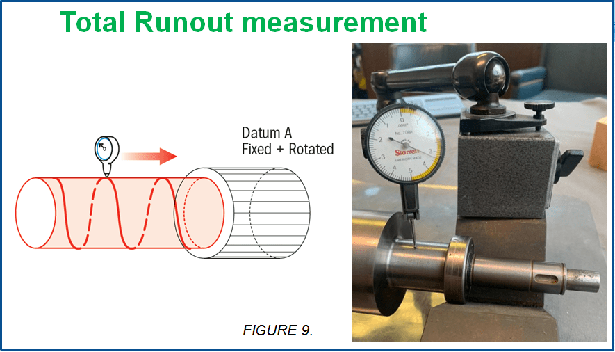
Total Runout is measured by fixing the datum features (typically an axis) and rotating the part along the rotational axis. The part is usually constrained with a set of V-blocks or a spindle of some sort that will constrain the part while allowing it to rotate. To measure total runout, a series of gauges must be linked to take their measurement in reference to each other – similar to how cylindricity is measured.
Another method for measuring total runout is to take one gauge held perpendicular to the surface of the part, and slowly move it across the surface of the part axially as the part is rotated. If the gauge varies at any point by more than the total runout tolerance, the part would be out of spec.
Relation to Other GD&T Symbols.
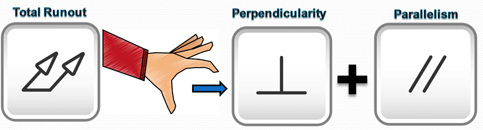
Total Runout Controls: Concentricity, Perpendicularity/Parallelism (feature of size axis), Cylindricity, Circularity, Straightness and of course normal Circular Runout.
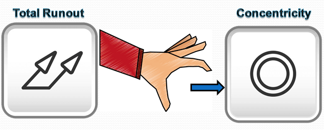
Total Runout captures Concentricity by controlling the radial alignment of the datum’s axis to the feature’s median points.
Perpendicularity or Paralelism of the two features would be controlled because if the central axis is offset by an angle, the end of the workpiece would runout far more than the side closer to the datum.
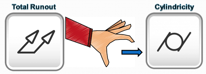
Cylindricity would also be controlled because any form variation along a cylindrical surface would show up in the total runout. If the feature is a cylinder, any circularity or straightness would cause the height gauge to fluctuate, even if the part is perfectly coaxial.
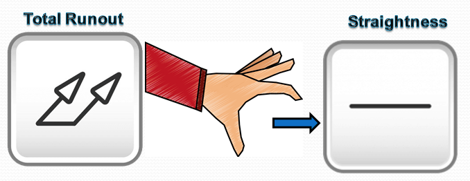
Axis Straightness is controlled because any bow in the feature would cause the end of the piece to have a larger runout at the end of the work piece. Surface Straightness would also be controlled because you are now controlling any form variation across the entire surface. (this would control whether the part is a cylinder or a tapered feature)
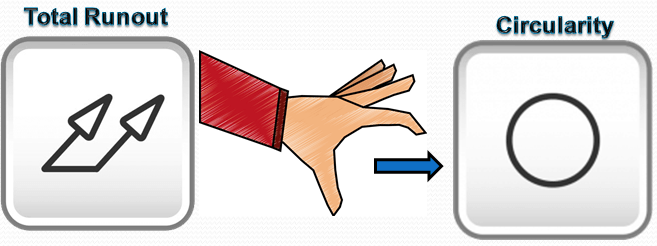
Circularity is controlled because any form variation along surface, would be picked up by the total runout measurement.
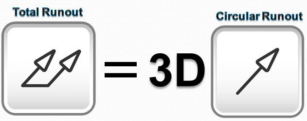
Total Runout is, of course, the 3D version of Runout or circular runout (the term runout on its own, always implies circular runout). While total runout takes the surface of the entire part in a 3D tolerance zone, runout or circular runout only captures the cross-section of the part.
Final Notes
Combination of Tolerances: Total Runout combines concentricity which is axis to axis relation of a part, with cylindricity. Since Cylindricity is actually a combination of Circularity and Straightness, all of these individual geometric symbols are controlled when total runout is used.
Regardless of Feature Size: Total Runout is always RFS (regardless of feature size) meaning that the boundary formed by the dimensions is the entire part envelope that the part can exist regardless of how large the runout tolerance is. It is directly referenced to a datum axis so a functional gauge or MMC cannot be called out.
FAQ: Can total runout tolerance be applied to a cone?
A: For any features other than cylinders or flat perpendicular faces, the indicator would have to be swept along a path neither parallel nor perpendicular to the datum axis. Since the standards have not adequately defined these paths, avoid such applications.
FAQ: Can I apply a runout tolerance to a gear or a screw thread?
A: Avoid doing that. Remember that a runout tolerance applies to the FIM generated by surface elements. Some experts suggest modifying the runout tolerance by adding the note PITCH CYLINDER. We feel that subverts the purpose for runout tolerance and requires unique and complicated inspection methods. Consider a positional tolerance instead.
FAQ: A feature’s runout tolerance has to be less than its size tolerance, right?
A: Wrong. A feature’s size limits don’t control its runout; neither does a runout tolerance control the feature’s size. Depending on design considerations, a runout tolerance may be less than, equal to, or greater than the size tolerance. One can imagine scenarios justifying just about any ratio. That’s why it’s important to consider each runout tolerance independently and carefully.
FAQ: Can I apply a runout tolerance “unless otherwise specified” in the tolerance block or by a general note?
A: Yes, but identify a datum feature and reference it with the runout tolerance. A runout tolerance with no datum reference is meaningless and illegal. Many novice inspectors encountering a general runout tolerance with no datum reference start checking every possible pairing of features—for five diameters, that’s 20 checks! Also, consider each feature to which the runout tolerance will apply and be careful not to rob any feature of usable and needed tolerance.

Leave a comment