
Among the 14 used GD & T symbols in the category of Location Tolerances there are 3 types.
- 1. The Position Tolerance
- 2. The Concentricity Tolerance
- 3. The Symmetry Tolerance
From these 3 tolerance types, only the Position Tolerance is often used as it is also easy to measure. The other 2 are in general replaced using a combination of other easy to measure tolerances such as Form Tolerances (Straightness, Flatness) or Direction Tolerance (Perpendicularity, Parallelism) or Position Tolerance itself.
But however, in some cases is usefull to specify the Concentricity or the Symmetry tolerance, even if an very accurate measurement of both is not always easy do to. In this article let’s have a look at SYMMETRY Tolerance.
Description
The Symmetry tolerance is similar with (coaxiality) Concentricity tolerance, both are a special case of the position. Concentricity corresponds to a rotational or point symmetry to a reference axis, while simple symmetry is a mirror symmetry with a reference plane, line or point.
Symmetrical components are very common: The symmetry tolerance is important because the usual dimensioning does not contain any symmetry tolerance, not even with the Envelope principle. A lack of symmetry or information about coaxiality are a major cause, which is why around 80% of the drawings are incomplete in practice. Symmetry is much like Concentricity, except that it controls rectangular features and involves 2 imaginary flat planes, much like parallelism.
Definition: GD&T Symmetry is a 3-Dimensional tolerance that is used to ensure that 2 features on a part are uniform across a datum plane. An established “true” central plane is established from the datum and for the symmetry to be in tolerance, the median distance between every point on the 2 surface features needs to fall near that central plane. Each set of points on the reference features would have a midpoint that is right between the 2. If you take all the midpoints of the entire surface, this must lie within the tolerance zone to be in specification.
Symmetry is not a very common GD&T callout since it has very limited functional uses (centering location is done with Position) and the verification and measurement of symmetry can be difficult (See: Final Notes below).
The Symbol represents a long line symmetrically placed between 2 shorter ones (as shown in figure 1.) This symbol is specified in the left compartment of the feature control frame and it is used to describe measurements from derived median plane as opposed to 2 surfaces.

The Tolerance call out: Symmetry = Toleranced and datum elements are in general 2 planes or 2 lines at a distance of tsy as symmetry tolerance specified in the fearture control plane, which means that tolerance arrow or reference triangle are always on the coresponding dimension arrow.
A Symmetry tolerance is specified using a feature control frame displaying the characteristic symbol for either “concentricity” (two concentric circles) or “symmetry about a plane” (three stacked horizontal bars). The feature control frame includes the symmetry tolerance value followed by 1, 2, or 3 datum references. There’s no practical interaction between a feature’s size and the acceptable magnitude of lopsidedness. Thus, material condition modifier symbols, MMC and LMC, are prohibited for all symmetry tolerances and their datum references.

Recalling the basics for position tolerance, much of what I said about concentricity and some characteristics of position tolerance can be applied to symmetry as well. In summary the symmetry characteristics as the following:
- Datum and toleranced features are often midplanes or lines. However, it can also be axes (e.g. of transversal holes) or real planes;
- Tubular tolerance zones are rare, but if that’s the case then the limit deviation is equal to half of symmetry tolerance tsy/2
- The Symmetry tolerance includes the parallelism of the toleranced element and its straightness, and in the case of a tolerated plane also the flatness.
How does it work?
The Math Standard describes in detail how symmetry tolerancing works. Generically, a symmetry tolerance prescribes that a datum plane or axis is extended all the way through the controlled feature.

We usually think of symmetry as the 2-fold mirror-image sort of balance about a center plane shown in Fig. 3 (a) and (b). There are other types as well. A 3-lobe cam can have symmetry, both the obvious 2-fold kind about a plane as shown in Fig. 3(c), and a 3-fold kind about an axis as shown in Fig. 3(d). The pentagon shown in Fig. 3(e) has 5-fold symmetry about an axis. GD&T’s symmetry tolerances apply at the lowest order of symmetry—the lowest prime divisor of the number of sides, facets, blades, lobes, etc., that the feature is supposed to have. Thus, a 27-blade turbine would be controlled by 3-fold symmetry. For a hexagonal flange (6 sides), 2-fold symmetry applies. By agreement, a nominally round shaft or sphere is subject to 2-fold symmetry as well.
As shown in See Fig. 4 which also applies to concentricity, from any single point on that datum within the feature, vectors or rays perpendicular to the datum are projected to intersect the feature surface(s). For common 2-fold symmetry, 2 rays are projected, 180° apart. From those intersection points, a median point (centroid) is constructed. This median point shall lie within a tolerance zone that is uniformly distributed about the datum. If one of the construction rays hits a small dent in the surface, but an opposite ray intersects a uniform portion of the surface, the median point might lie outside the tolerance zone.
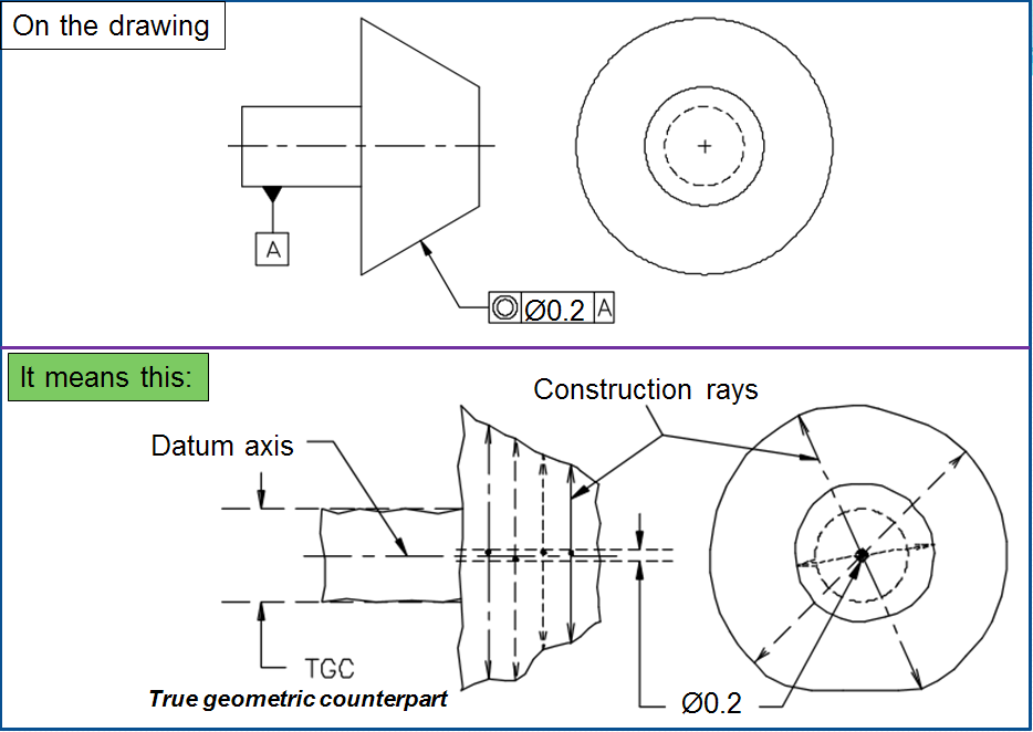
Thus, symmetry tolerancing demands that any local “low spot” in the feature surface be countered by another “low spot” opposite. Similarly, any “high spot” must have a corresponding “high spot” opposite it. Symmetry tolerancing primarily prevents “lopsidedness.”
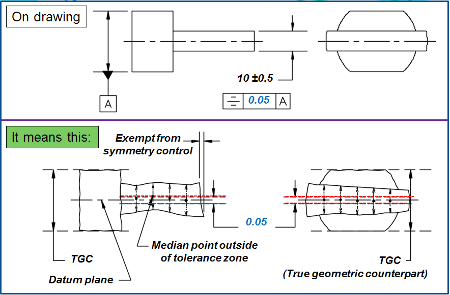
As you can imagine, inspecting a symmetry tolerance is no simple matter. Generally, a CMM with advanced software or a dedicated machine with a precision spindle should be used. For an entire feature to conform to its symmetry tolerance, all median points shall conform, for every possible ray pattern, for every possible origin point on the datum plane or axis within the feature. Although it’s impossible to verify infinitely many median points, a sufficient sample (perhaps dozens or hundreds) should be constructed and evaluated. At the ends of every actual bore or shaft, and at the edges of every slot or tab, for example, the terminating faces will not be perfectly perpendicular to the symmetry datum. Though one ray might intersect a part surface at the extreme edge, the other ray(s) could just miss and shoot off into the air. This also happens at any cross-hole, flat, keyseat, or other interruption along the controlled feature(s). Obviously then, unopposed points on the surface(s), as depicted in Fig. 6 below, are exempt from symmetry control. Otherwise, it would be impossible for any feature to conform.
Tolerance zone
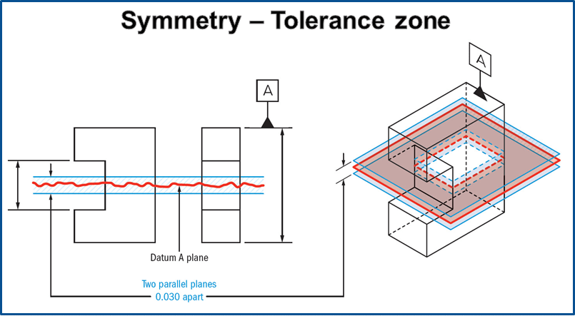
Parallel Planes on equal sides of a central datum plane. The median points of the symmetrical surfaces must all lie within this zone.
Datums for Symmetry Control Symmetry control requires a DRF (Datum Reference Frame). A primary datum plane or axis usually arrests the 3 or 4 degrees of freedom needed for symmetry control. All datum references shall be RFS (Regardless of Feature Size).
Symmetry Tolerance about a Datum Plane
In Fig 6, from any point on the datum plane between the controlled surfaces, two rays are projected perpendicular to the datum, 180° apart (colinear). The rays intersect the surfaces on either side of the datum. The midpoint between those two surface points shall be contained between two parallel planes, separated by a distance equal to the symmetry tolerance value. The two tolerance zone planes are equally disposed about (thus, parallel to) the datum plane. All midpoints shall conform for every possible origin point on the datum plane between the controlled surfaces. As the rays sweep, they generate a locus of midpoints subtly different from the derived median plane. The symmetry rays are perpendicular to the datum plane, while the derived median plane’s construction lines are perpendicular to the feature’s own center plane.
It’s not clear why the methods (for concentricity vs. symmetry) differ or whether the difference is ever significant. Symmetry tolerancing about a plane does not limit feature size, surface flatness, parallelism, or straightness of surface line elements. Again, the objective is that the part’s mass be equally distributed about the datum. Although a symmetry or concentricity tolerance provides little or no form control, it always accompanies a size dimension that provides some restriction on form deviation according to Rule #1.
According to ASME Y14.5M-1994, the Rule #1 decrees that: “Where only a tolerance of size is specified, the limits of size of an individual feature prescribe the extent to which variations in its form—as well as in its size—are allowed”
When is the Symmetry tolerance used?
When you want to make sure that the center plane of 2 symmetric features is always held exactly center AND has even form along the surface of the part. This symbol only has specific uses for mass balance and form distribution. However, in most cases it is better to avoid using it since this is a very difficult callout to measure and can easily be replaced with a Position tolerance.
Symmetry Tolerancing of Yore (Past Practice)= Until the 1994 edition, Y14.5 described concentricity tolerancing as an “axis” control, restraining a separate “axis” at each cross-section of the controlled feature. A definition was not provided for axis, nor was there any explanation of how a 2-dimensional imperfect shape (a circular cross-section) could even have such a thing. As soon as the Y14.5 Subcommittee defined the term feature axis, it realized 2 things about the feature axis:
1st- it’s what ordinary positional tolerance RFS (Regardless of Feature Size) controls, and 2nd-it has nothing to do with lopsidedness (balance).
From there, symmetry rays, median points, and worms evolved. The “Symmetry Tolerance” of the 1973 edition was exactly the same as positional tolerance applied to a noncylindrical feature RFS. (See the note at the bottom of Fig. 140 in that edition.) The 3-horizontal bars symbol was simply shorthand, saving draftsmen from having to draw circle-S symbols. Partly because of its redundancy, the “symmetry tolerance” symbol was cut from the 1982 edition.
When Do We Use a Symmetry Tolerance? Under any symmetry tolerance, a surface element on one “side” of the datum can “do anything it wants” just as long as the opposing element(s) mirrors it. This would appear to be useful for a rotating part that must be dynamically balanced. However, there are few such assemblies where GD&T alone can adequately control balance. More often, the assembly includes setscrews, keyseats, welds, or other attachments that entail a balancing operation after assembly. And ironically, a centerless ground shaft might have near-perfect dynamic balance, yet fail the concentricity tolerance because its out-of-roundness is 3-lobed.
Symmetry example of use: If you had a rotating U-Joint, a groove that needed to always have even balance, you would need to make sure that the mating part is always located to fall into the center of the groove and that the surface form is properly balanced. Instead of widening the groove causing the conncetion to be loose, you could constrain it with symmetry.

The part would then need to be measured to ensure that all the median points of the sides of the latch block are symmetrical about the central axis. The part would have to be measured in the following way:
- Measure the width and location of both sides of the block reference by datum A (40mm) and determine where the exact median plane is located to establish our tolerance zone.
- Side 1 and Side 2 of the part are scanned for their actual profiles
- Using a program, the median points of the Side 1 and Side 2 scans are laid over the virtual tolerance zone planes and determined if they are in tolerance.
Let’s see now some of the most frequent examples of use for symmetry tolerance:
Example 1. – Groove related to parallel surfaces
In FIG 8 a) The center plane of the groove is tolerated & the reference datum is the median plane of the parallel inner surfaces. The reference datum can be specified in 2 ways. Either as i) datum reference with the triangle on the dimension arrow and additional geometrical tolerances specified or as ii) separate designation of reference planes ‘equivalent with i), but without additional tolerances.
The simples way, is to specify the reference datum with the triangle on the dimension line of the feature of 50mm, the same as done when axes must be identified. The reference plane is then the middle plane of the 2 parallel planes that are free from outside play and free from constrains, for instance like the jaws of a test vise. The tolerated middle plane of the groove on the other hand is determined point by point by the opposite surfaces from the groove. All these points must lie between boundary planes at a distance of ±tsy/2 = ±0,1 from the reference plane.
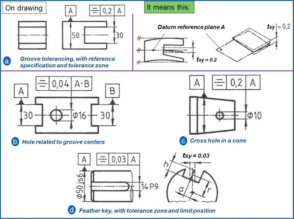
Example 2. – Hole related to groove centers
In FIG 8 b) The reference plane is formed by the 2 grooves; but in this case coresponding problems appear the same as for common axes from 2 holes. The hole axis may deviate from the reference plane by up to ±0,02mm on both sides.
Example 3. – Cross hole (related to an axis) in a cone
In FIG 8 c) The tolerance zone is delimited by two planes at a distance of ±0.1mm from the axis of the cone, which can be rotated freely around the axis.The axis of the cross hole may therefore not pass the taper axis by more than tsy/2 = 0.1 mm.
Example 4. – Symmetry tolerance of a feather key
As shown in FIG 8 d) In order for a feather key to carry the load sufficiently equal, the groove must be parallel along the axis of the shaft extension and “align” with the axis in the cross section. Both deviations are included in the tolerance zone for symmetry. This tolerance can be rotated around the reference axis A. The central plane of the keyway may deviate from the axis direction by tsy = 0.03 mm in the longitudinal direction, while in the cross-section it can pass at a distance a from the reference axis by a maximum distance a on both sides.
Note 1: The parallelism to the axis is particularly important for the function of the feather key, while the distance a is unimportant. Any plastic deformation of the feather key in the vertical direction is also only determined by the symmetry tolerance tsy, but not by distance a. However in case that distance a is used, then it calculates itself sufficiently accurate as: a = tsy*r/ h
Note 2: For the feather key, simply specifying a parallelism tolerance is not enough, because this only affects the longitudinal direction and not the cross section. On the other hand, it can make sense to tolerate parallelism in addition to symmetry if the parallelism tolerance is smaller than the symmetry tolerance.
Special cases of symmetry tolerancing
Not all functional requirements can be covered with the means of DIN EN ISO 1101 alone, therefore it may be necessary to meaningfully transfer the standardized information. In doing so, we should always start from the tolerance zone and pay attention to clarity (if necessary, also by means of additional information). FIG 9 shows 3 such symmetry tolerance examples.
Example 5. – Intersection of 2 axes + the tolerance zone
In FIG 9 a) If the intersection is outside the toleranced hole, DIN EN ISO 1101 does not offer a solution. The reference axis A can be extended as desired, but the tolerated axis can only be extended over a projected tolerance zone. Since this is only an intersection point, the dimension marked with (P) (meaning Projected tolerance) for the length of the tolerance zone shrinks to 0 and is therefore not entered as a number (as a suggestion). Yet the tolerance zone is at the intersection of the axes, symmetrical to the reference axis A.

Example 6. – Cylindrical tolerance zone + the complete reference frame
In FIG 9 b) The ideal location for the hole is perpendicular to the main surface A and in the middle of the two pairs of outer surfaces B and C. In this location cylindrical tolerance zone is also possible – analogous to the position tolerance.
Example 7. – Alignment of 2 real surfaces
So far all examples of symmetry tolerance refered to exclusivelly derived form elements; yet in this example, the 2 involved elements are real surfaces. In FIG 9 c) The reference datum A is determined from the reference plane using the LMC (Least Material Condition). The tolerance zone delimited by 2 planes at a distance of ±0,05 mm, limits the location, the paralellism and the flatness of the tolerated surface. This tolerancing should NOT be applied if the median spacing of the surfaces is significantly bigger than the length of the reference elements. In general for such surfaces, preferably is used a Flatness tolerance on Common Zone (CZ).
Gauging / Measurement
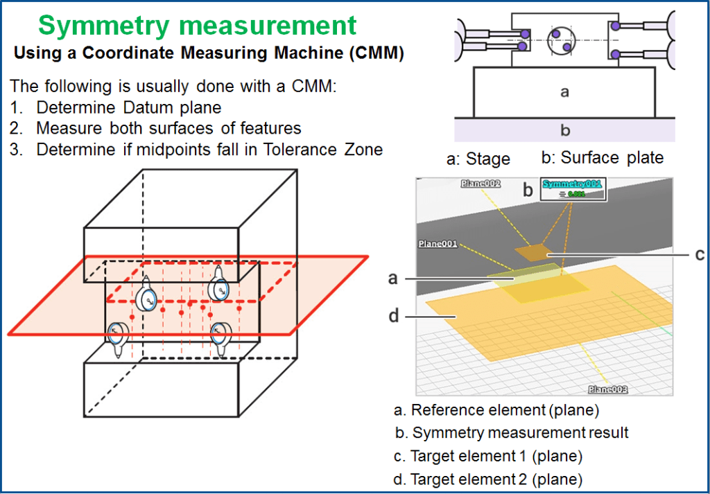
As stated before, symmetry is very difficult to measure. Due to its tolerance zone being constrained to a virtual plane, you cannot have a gauge to properly measure this feature quickly. Usually, to measure symmetry, a CMM is set up to calculate the theoretical midpoint datum plane, measure the surfaces of both required surfaces, and then determine where the midpoints lie in reference to the datum plane. This is a complex and sometimes inaccurate method for determining if a part is symmetrical.
However the symmetry measurement can be done in 2 ways:
Using an analog caliper or micrometer to check the symmetry. This is useful for repeated measurements of single items thanks to its simple, quick usability. Both calipers and micrometers come in various types, which are selectively used depending on the location and form to be measured.
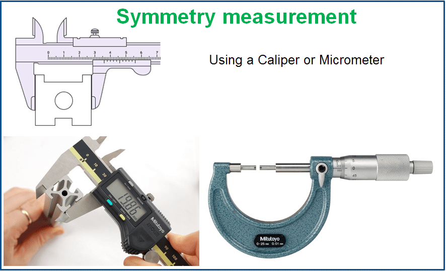
DISADVANTAGES = The accuracy of measured values and speed of measurement rely on the skill level of the operator in addition to the measurement error of the individual instrument. Furthermore, while size can be measured as these instruments measure the length between two points, geometric tolerance (form) is difficult to measure. Additionally, the measurement data needs to be handwritten for recordkeeping.
Using a Coordinate Measuring Machine (CMM) – The reference element (plane) set-up and the deviation from the target element (plane) can be quickly and accurately measured by anyone just by putting the stylus on each measurement point.
The measurement result is recorded in the measuring machine.
Relation to other GD & T Symbols

Symmetry is the non-circular version of concentricity.
While concentricity really is a focus of symmetry around a datum axis, The Symmetry Symbol is a focus on symmetry over a datum plane. Both symbols focus on the theoretical center datum being constrained within a specific limit to ensure that the entire structure is uniform.
Final Notes
Symmetry should be avoided in most cases due to its specific functional requirements and measurement difficulty.
With flatness, parallelism and true position, you can locate the exact same constraints on the part, albeit with more callouts and measurements required. However since true position can be measured with a gauge (if MMC is used), and flatness is automatically controlled by the size dimension & directly measured off the surfaces, these can be controlled within a process and do not require timely CMM measurements.
FAQ: Could a note be added to modify the concentricity tolerance for a cylinder to 3-fold symmetry?
A: Sure.
FAQ: Can I use a symmetry tolerance if the feature to be controlled is offset (not coaxial or coplanar) from the datum feature?
A: Nothing in the standard prohibits that, either. Be sure to add a basic dimension to specify the offset. You may also need 2 or even 3 datum references.

Leave a comment