
In this post I’ll show you how to design a Viking Helmet made of 2 main componets :The Helmet Body and the Horn Body, which will make the final assembly in a Viking Helmet Product. Let’s start with The Helmet!!
THE HELMET
STEP 1
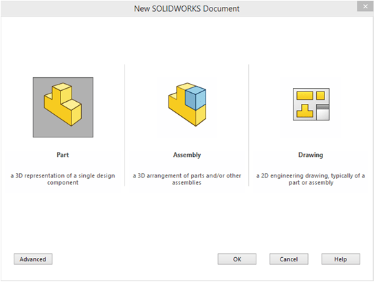
Create new part
STEP 2
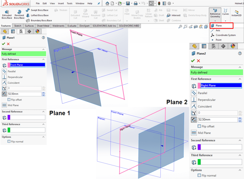
Create 2 reference planes, each at the same offset of 52.5mm as shown:
STEP 3
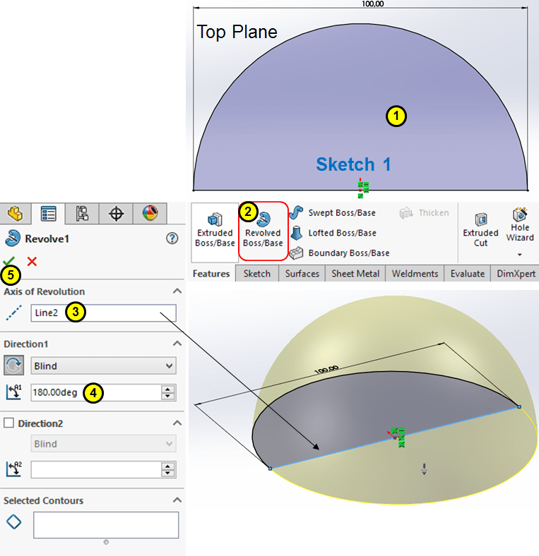
Create a half-sphere by drawing its profile on Top Plane and apply the Revolve feature as shown:
STEP 4
Apply a Shell feature with a wall thinkness of 4mm:

STEP 5
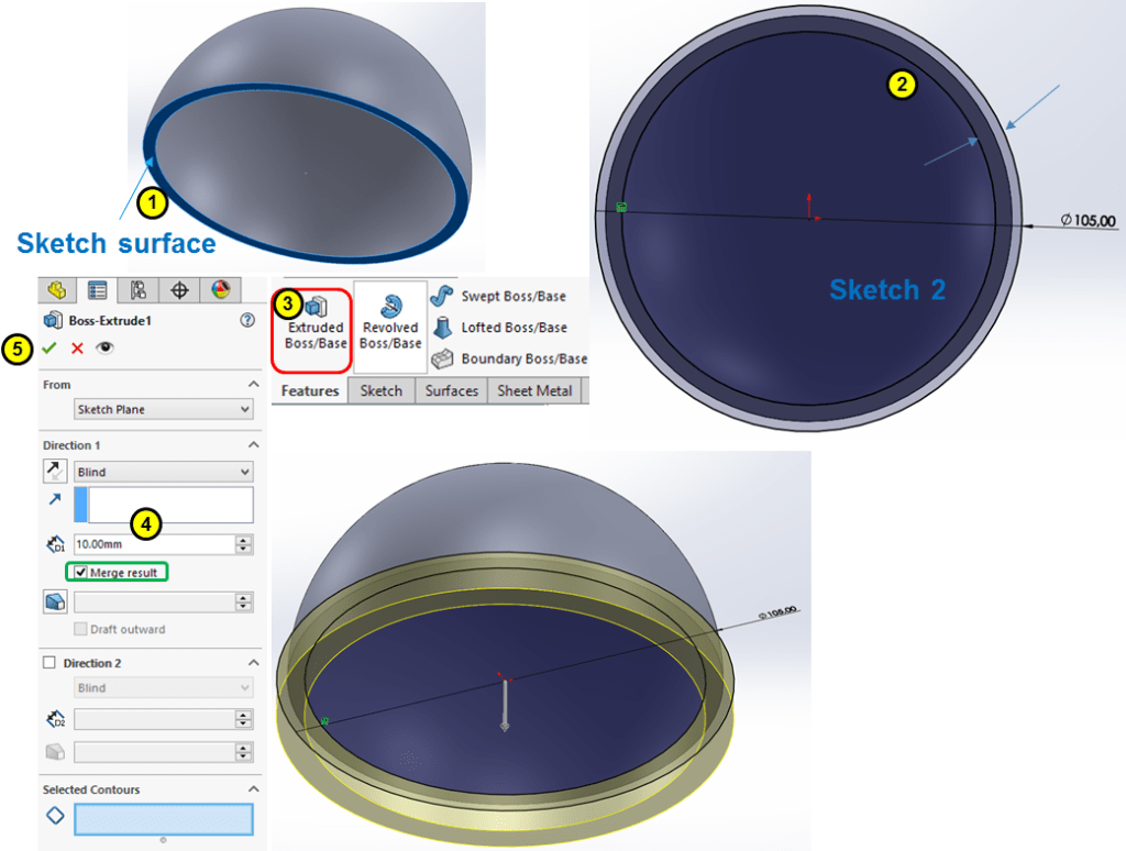
Create a thick base on the shell edge outwards as shown:
STEP 6.
Create a Swept boss, on the middle of the outer shell, first by drawing the 2 necesssary sketches as shown:
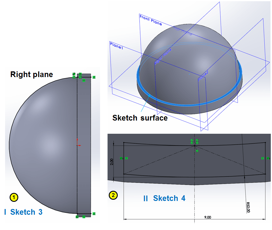
… then sweep the Sketch 4 along the Sketch 5 as shown:

STEP 7.
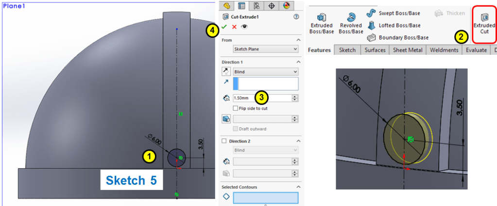
Apply a circular cut-out on the front side (diameter Ø = 6mm+depth=1.5mm):
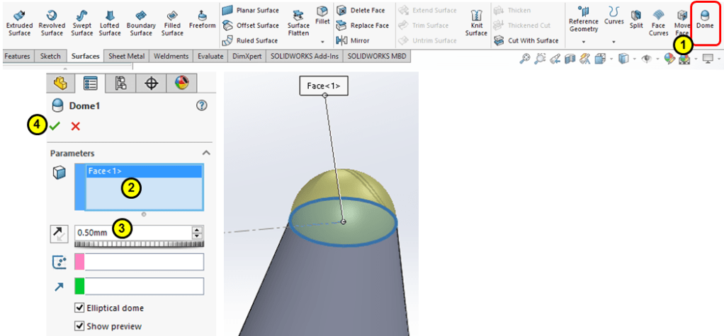
STEP 8.
On the bottom surface of the cut-out, create a, eliptical dome of 2.5mm height:

STEP 9.
Create a circular pattern of 10 instances including the Circular cut-out and the Dome, along the edge of the middle swept boss:

STEP 10.

Extract the inner surface of the shell with offset = 0mm
STEP 11.
Create a circular cut-out through all on both sides in the middle of the shell as shown:

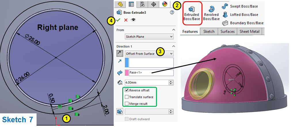
STEP 12.
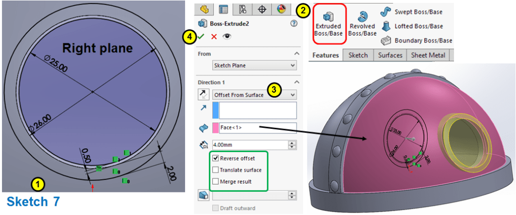
On one of the side edges of the circular cut-out apply an Extruded boss as a 4mm offset from outer surface as shown:
STEP 13.
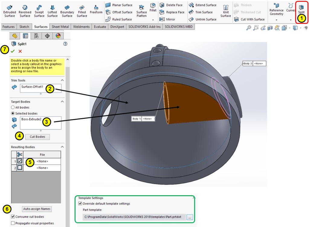
Remove the inside material generated by the previous extruded boss by a Split feature consuming the cut bodies as shown:
STEP 14.
Similar with STEP 12, apply the extruded boss on the other side as shown:
STEP 15.
Item with STEP 13:

STEP 16.
Create one body from the combination of both previous Splits features and the rest of the helmet body with a Combine feature as shown:

STEP 17.
Create the Face Shield with a profile sketched on the helmet edge as shown:


…then extrude the profile at 51mm length.
STEP 18.
Sketch the following profile on the Front Plane:

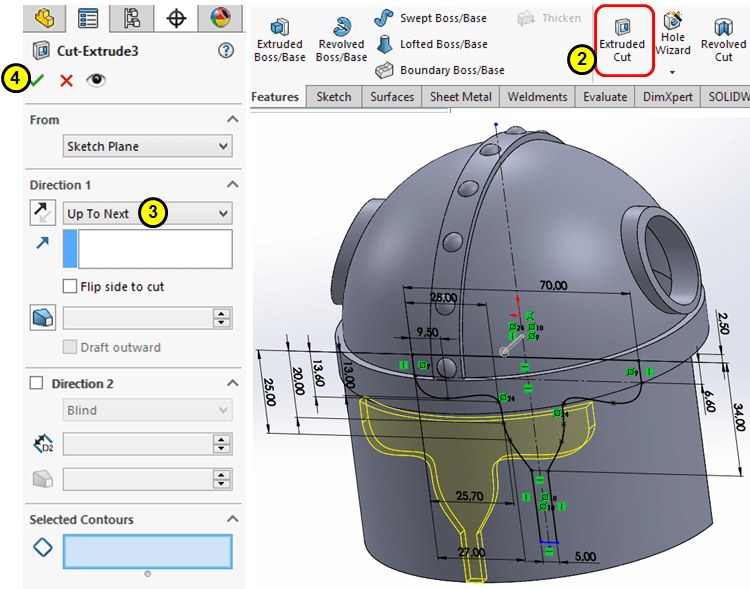
…then do an Extruded-cut Up to next as shown:
STEP 19.
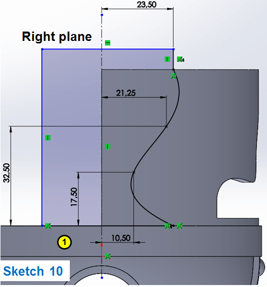
On Right Plane, sketch the profile as shown…
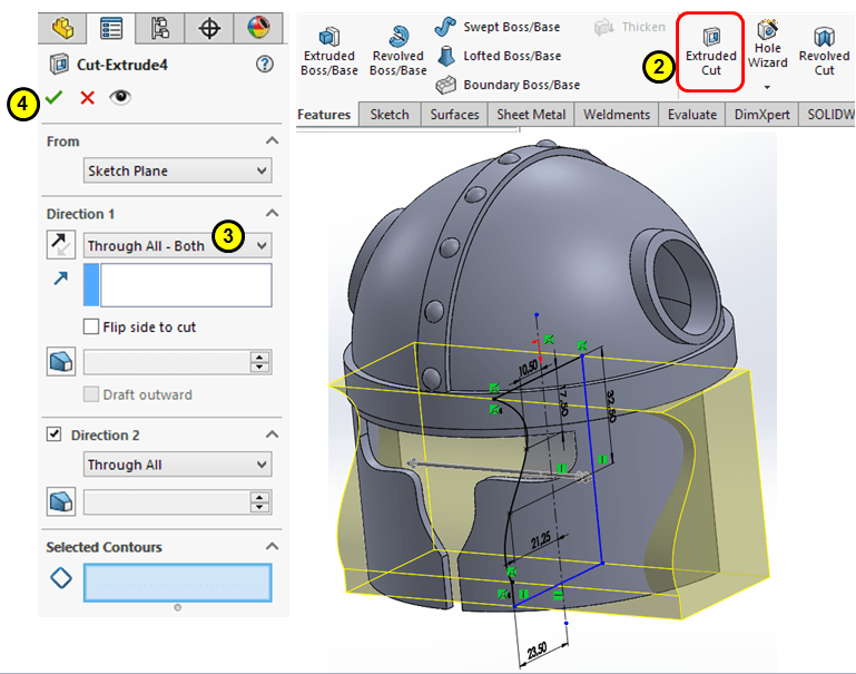
… then do and Extruded Cut through all-both.
STEP 20.
On Plane 2 sketch a circle of Ø = 8mm and do an extruded cut of 0.5mm depth as shown:

STEP 21.
Create a 3mm Dome feature on bottom surface of the previous cut as shown:

STEP 22.
Do a circular pattern along the bottom outer edge for 14 instances as shown:

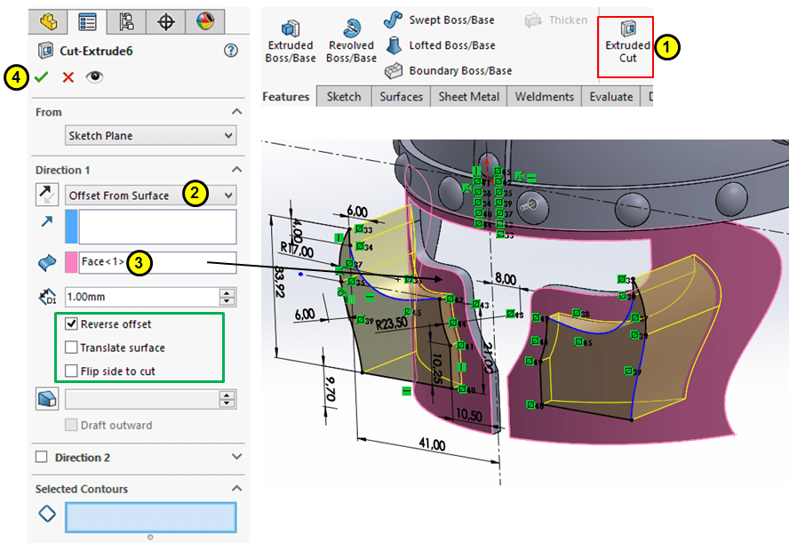
STEP 23.
On Plane 1 sketch the folowing profile…

… then do an extruded cut as shown:
STEP 24.
On Plane 1 sketch the folowing text:
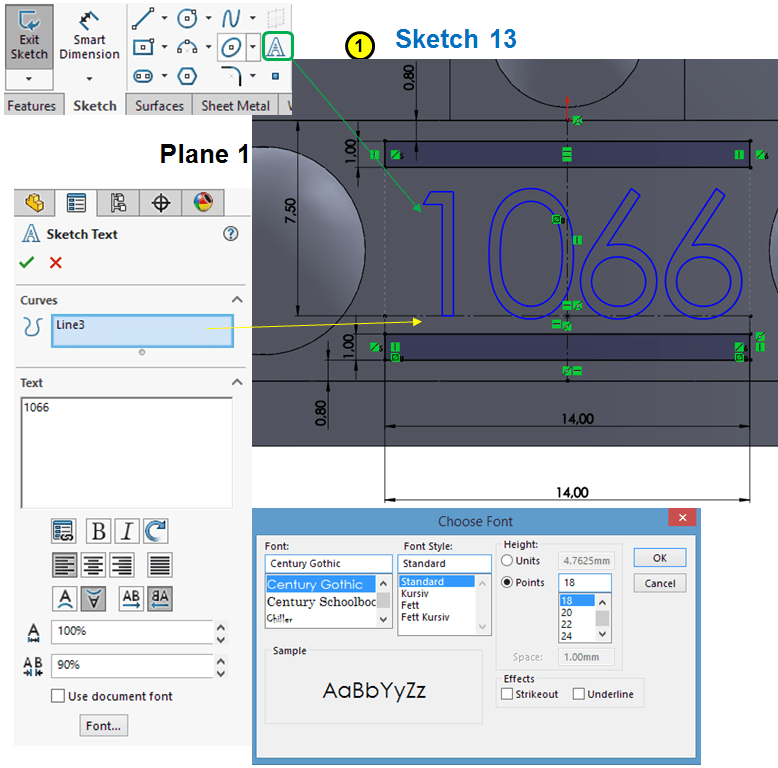
… then do an extruded boss as shown:

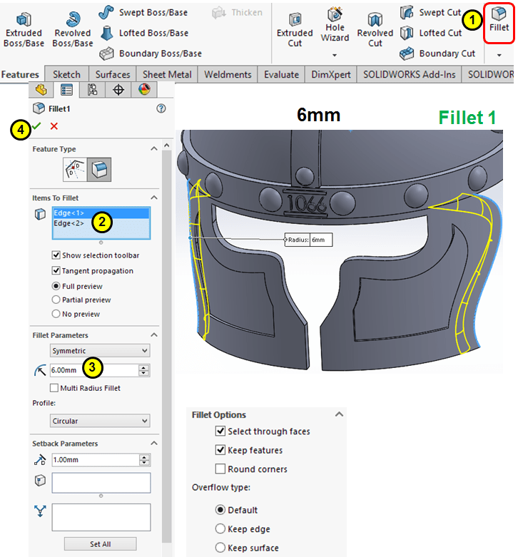
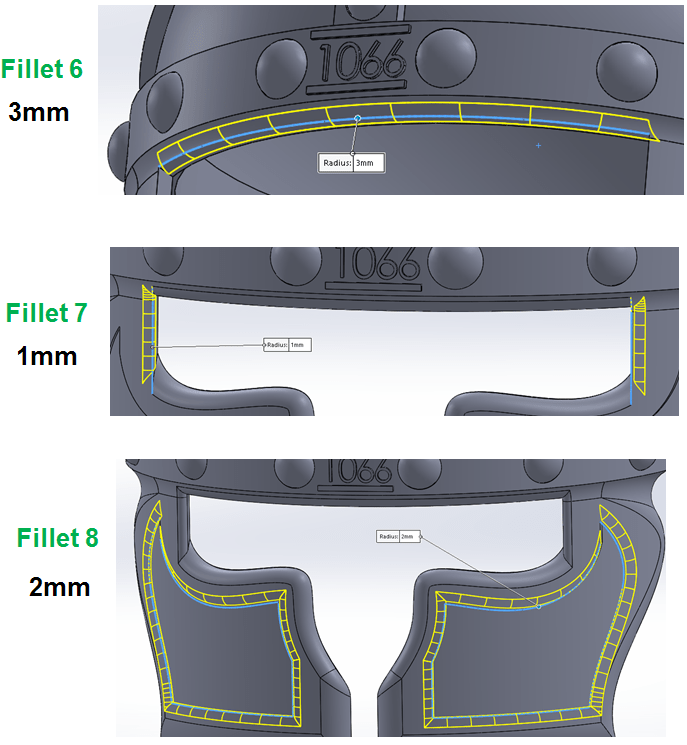
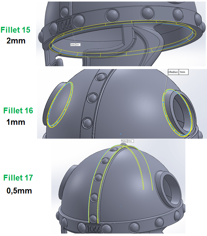
STEP 25.
Start adding fillets as follows:

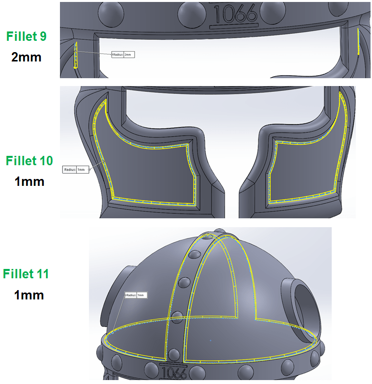


STEP 26.

In the Model Tree group all the fillets in a new folder as shown:
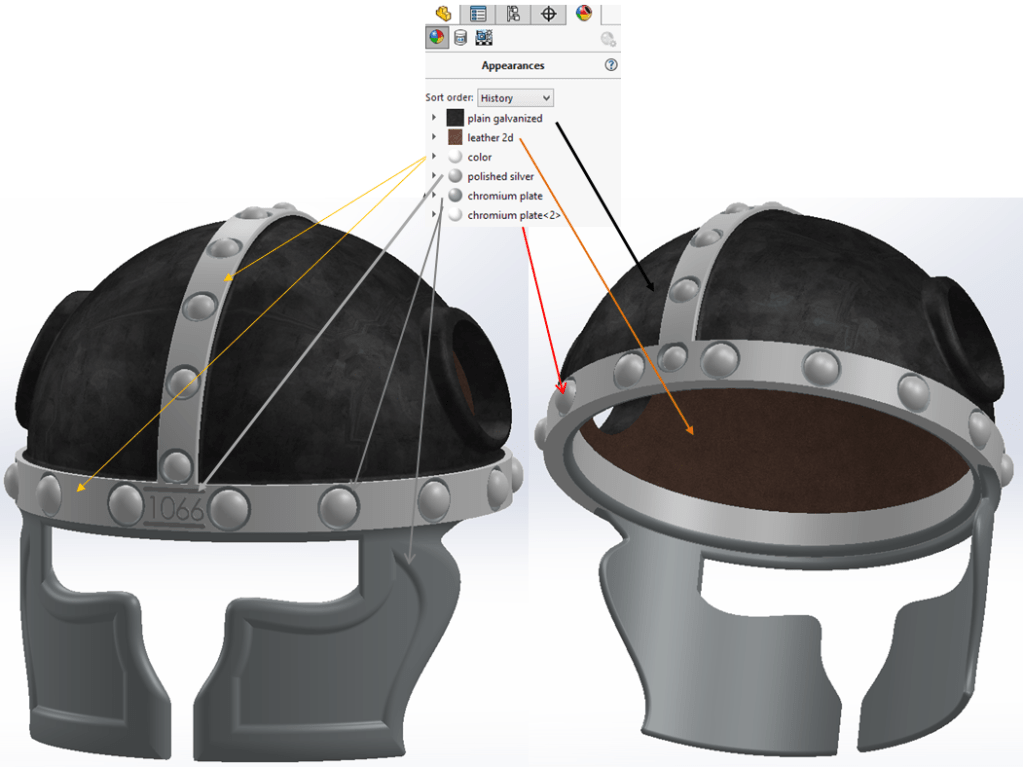
STEP 27.
Add appearances as follows:


THE HORN
STEP 1.

Create a new part
STEP 2.

Create a reference plane with 70mm offset from Top Plane
STEP 3.
Prepare the reference sketches for a Lofted Boss by drawing the following 3 profiles:

…and now click on the Lofted Boss icon and enter the parameters as follows:

STEP 4.
In the sharped side create a small Dome of 0.5mm
STEP 5.
To improve the esthetics a little bit, apply a 30mm Fillet as shown:

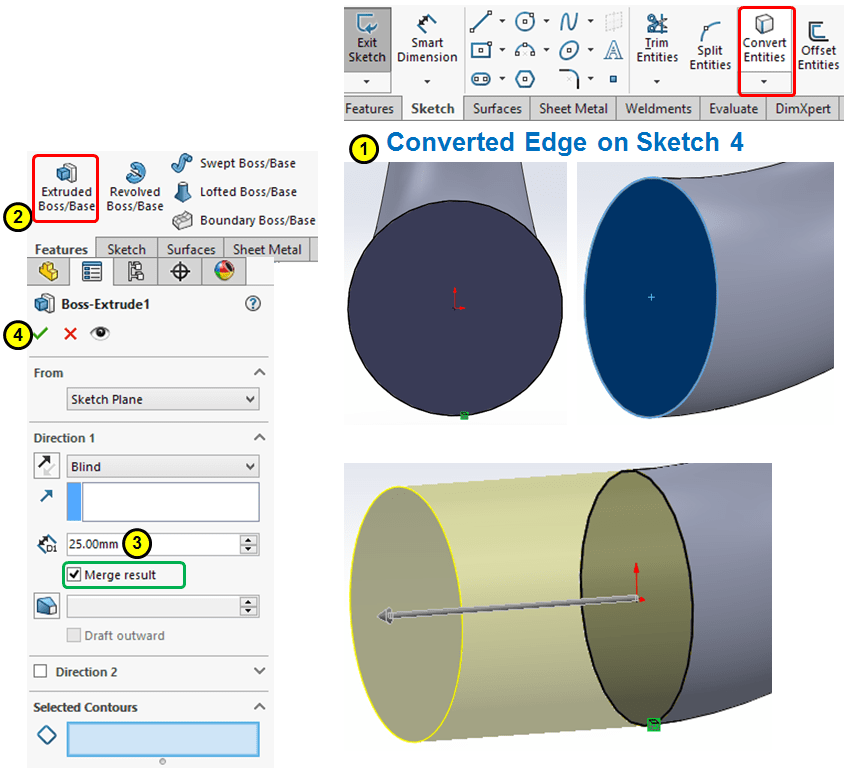
STEP 6.
Extrude the Horn base with 25mm thinkness:
STEP 7.
Generate a half-sphere on the Extruded base with a sketch on the Right plane as revolved surface:

STEP 8.
Cut the excess material with a Split feature as shown:

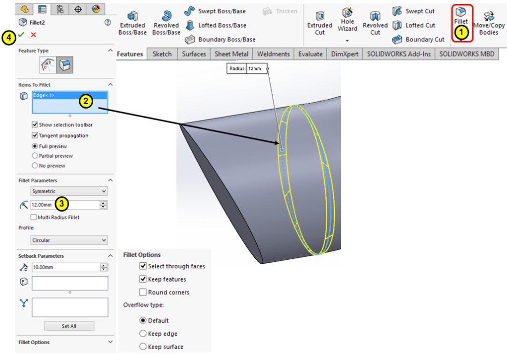
STEP 9.
Improve the esthetics with a 12mm Fillet as shown:
STEP 10.
Add appearance:

THE VIKING HELMET ASSEMBLY
STEP 1.

Create a new assembly
STEP 2.
When the assembly is created, SolidWorks asks you to upload the 1st component. Insert the component Helmet as shown:

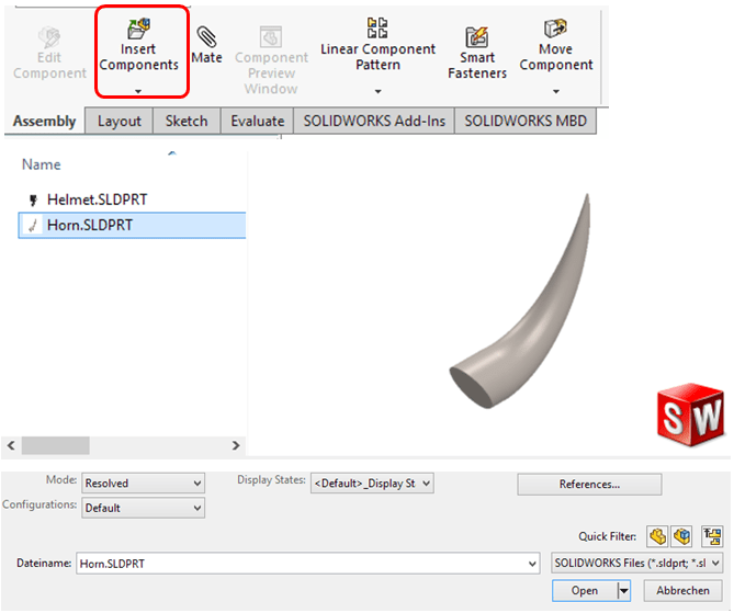
STEP 3.
Add the 2nd component, the Horn:
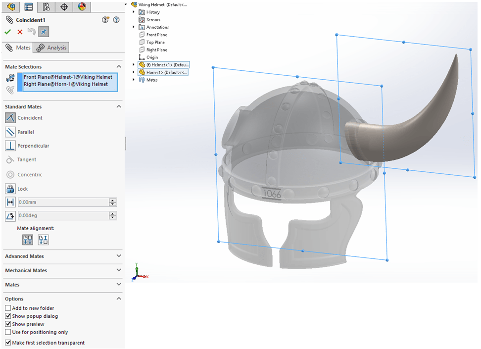
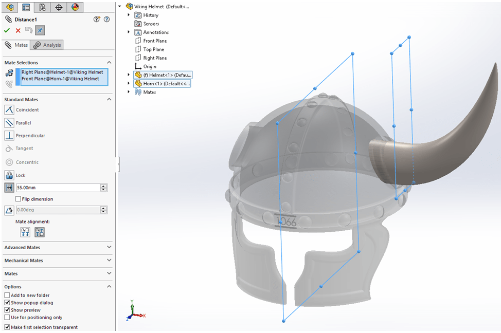
STEP 4.
Define the constrains between the components by clicking on the icon “Mate” and enter the parameters as shown:

STEP 5.
Continue adding constraints until the components are fully constaint:
STEP 6.
Mirror the horn as shown:

The final Viking Helmet product is ready.
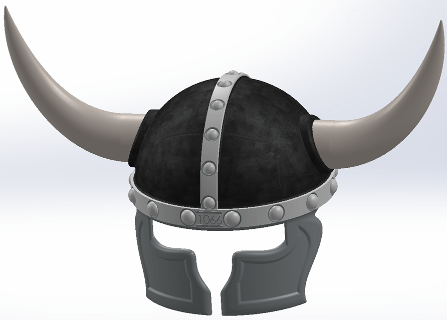

With Keyshot rendereing, the Helmet design can have a better appearance as shown:

This design work is also available as video version on my YouTube channel as embedded below:

I adore how your unique personality shines through in your words. It feels like we’re having a meaningful dialogue.
LikeLike