CREO PARAMETRIC 6.0 – KATANA SWORD DESIGN_Part 1 – Blade Design

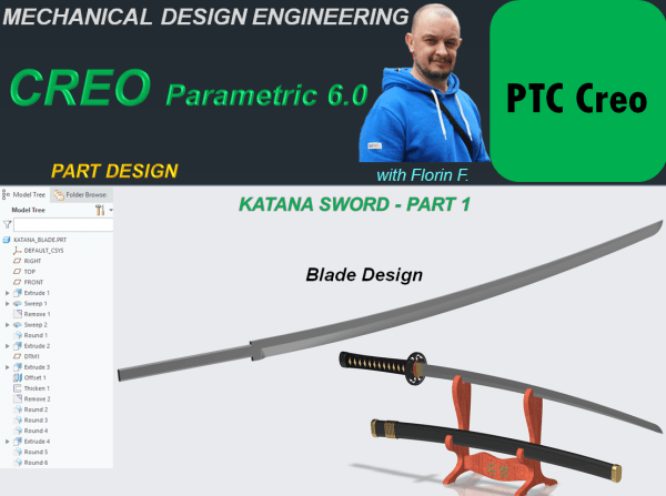
Katana Swords are one of the national symbols in Japan. Their story is trully fascinating and amazing. Having observed how this swords are made I've designed a Sword concept with CREO Parametric. My design process for such object goes as follows: KATANA BLADE STEP 1. Create New Part STEP 2. In Model Workbench click on... Continue Reading →

CREO PARAMETRIC 6.0 – SKATEBOARD DESIGN_Part 7 – Final Assembly

THE SKATEBOARD FINAL PRODUCT STEP 1. Create New Assembly and rename it Skateboard STEP 2. In Assembly Environment click on Assemble Icon and browse for the part called "Board" in project folder. Put the constraint on it as Default and click OK. Everything added afterwards will be refered to Board part. STEP 3. Continue to... Continue Reading →

CREO PARAMETRIC 6.0 – SKATEBOARD DESIGN_Part 6 – Sub-Asseblies

To create a product you must first design the component which are later put together in the final product assembly. But when every component is ready also it makes very much sense to group some components in a sub-assembly which will be part of the final one. Therefore let's create the sub-assemblies necessary for the... Continue Reading →

CREO PARAMETRIC 6.0 – SKATEBOARD DESIGN_Part 5 – Metalic Parts Design

An Assembly is a product made of single components joined to work together. Fixation elements are mandatory for every mechanical product to work as intended. So let's design the specific components and at the end we'll use the standard parts which are largelly available to download online. THE FIXATION PIN STEP 1. Create a New... Continue Reading →

CREO PARAMETRIC 6.0 – SKATEBOARD DESIGN_Part 4 – Rubber Parts Design

THE WHEEL STEP 1. Create a New part and rename it Wheel. STEP 2. In Model Environment click on Revolve icon and on Front Plane sketch the profile as shown, then revolve it around vertical axis. STEP 3. Apply rounds: STEP 4. Add rubber appearance: The Part looks like this: THE RUBBER BUSH I STEP... Continue Reading →

CREO PARAMETRIC 6.0 – SKATEBOARD DESIGN_Part 3 – Main Axle Design

The design procedure of the Main Axle of a skateboard done with CREO Parametric goes as follows: STEP 1. Create a new Part and rename it Main Axle STEP 2. Create 2 new datum planes with an offset of 65mm from the Front Plane on each side. STEP 3. On Front Plane Create the following... Continue Reading →

CREO PARAMETRIC 6.0 – SKATEBOARD DESIGN_Part 2 – Wheels Plate Design

The plate design for wheels of a Skateboard done in CREO parametric goes as follows: STEP 1. Create a New part and rename it WheelsPlate STEP 2. Click on Extrude icon and use the Sketch option from far upper right in Extrude window to create a center rectangle of 55x80 on the Top Plane and... Continue Reading →

CREO PARAMETRIC 6.0 – SKATEBOARD DESIGN_Part 1 – Board Design

This is Part 1 of the design work for Skatebord product. As usual I start this work by designing each component and later I will generate the final product assembly. The first component is the BOARD. STEP 1. Create a new part and rename it "Board" STEP 2. In Model Workbench click on Sweep icon... Continue Reading →

SOLIDWORKS – Pirate Ship Wheel Design

Let's design a Pirate Ship Wheel STEP 1. Create a new CAD file STEP 2. On Right Plane, sketch the 2 profiles for outer and inner wheel at a distance from each other of 360mm as shown: STEP 3. In the Features toolbar, click on Revolved Boss/Base icon and revole everithing completelly. STEP 4. On... Continue Reading →

SOLIDWORKS – Thor Hammer Design

Let's Design the Thor Hammer with SOLIDWORKS PART 1 - Handle STEP 1. Create New Part STEP 2. On the Right Plane draw the sketch as shown: STEP 3. In Featrues toolbar, click on Revolved Boss/Base icon and revolve the sketch completely. STEP 4. On Top Plane create a sketch as shown: STEP 5. In... Continue Reading →

Website Built with WordPress.com.

Up ↑