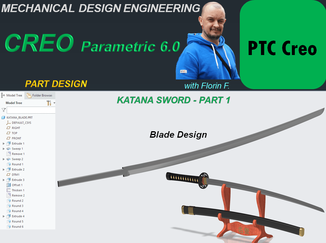
Katana Swords are one of the national symbols in Japan. Their story is trully fascinating and amazing. Having observed how this swords are made I’ve designed a Sword concept with CREO Parametric. My design process for such object goes as follows:
KATANA BLADE
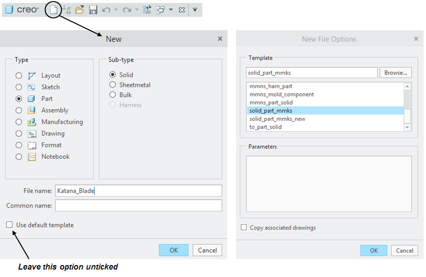
STEP 1.
Create New Part
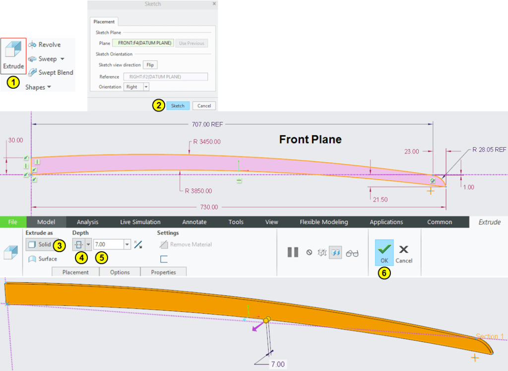
STEP 2.
In Model Workbench click on Extrude icon and on Front plane draw the sketch as shown and extrude it by mid-plane with 7mm.
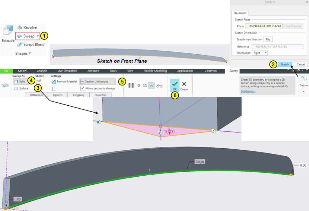
STEP 3.
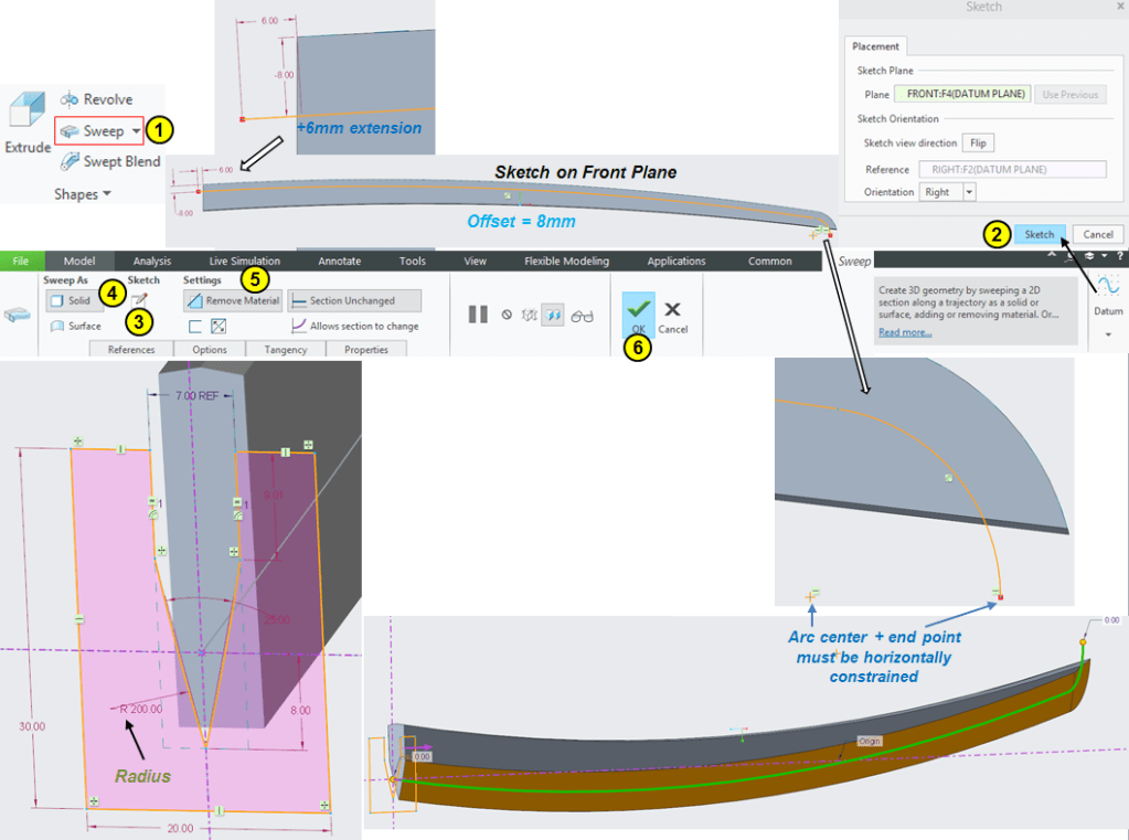
Click on Sweep icon and 1st create the Sweep trajectory as sketch on Front Plane by projecting the inner radius from the previous feature, then back in Sweep dialog box click on Sketch icon (n°3) and draw the sweep profile and click OK.
STEP 4.
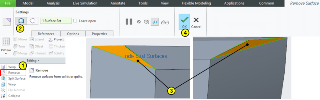
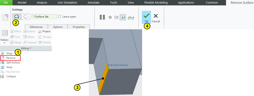
Because the Sweep is done normal to it’s trajectory as result the additional surfaces are created. In Editing ribbon, click on Remove icon and select the 2 end surfaces created by the sweep.
STEP 5.
Click on Sweep icon again and on front plane create a sketch by offsetting the outer profile at 8mm inwards. Then adjust the length with 6mm on handle side and on the tip constrain the end point horizontal with the arc center. Then back in Sweep dialog box click on the sketch icon (n°3), draw the skech as shown and click OK.
STEP 6.
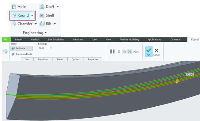
Round the middle side edges at 10mm
STEP 7.
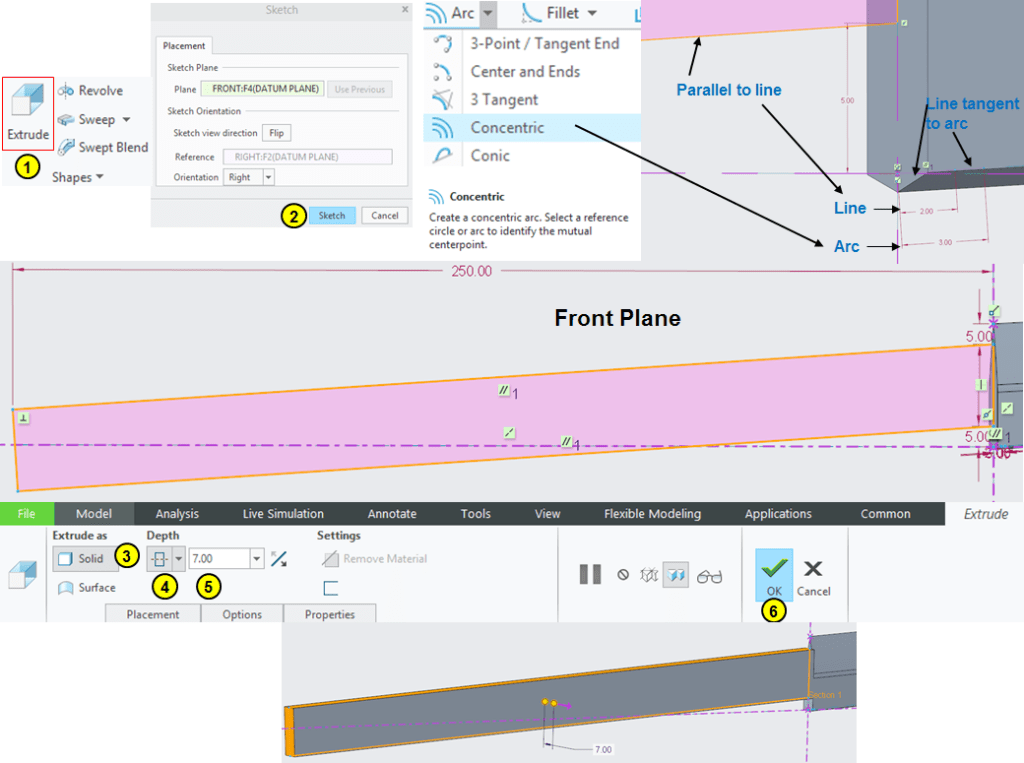
To create the handle side click on Extrude icon pay attention on how you create the sketch on the front plane. Do as follows: put both horizontal and vertical centerlines on the sketch center by default.
Then create a small concenric arc with the lower sidewise edge for instance with a 3mm length. Then starting from the origin point draw a small line of 2mm length and make it tangent with the arc and make both as construction elements. (dotted lines)
The lower edge of the handle must be parallel with the small line of 2mm. Then enter the rest of dimensional constrains as shown:
STEP 8.
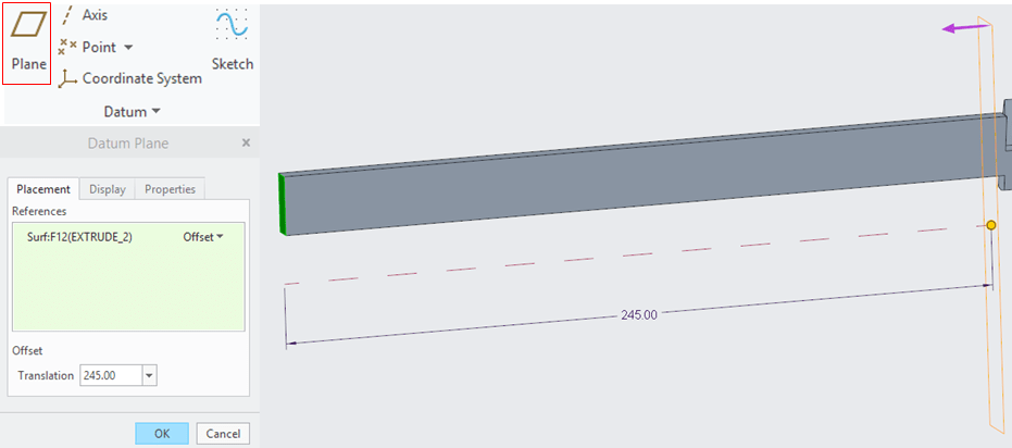
Create a new Datum plane (DTM1) as shown:
STEP 9.
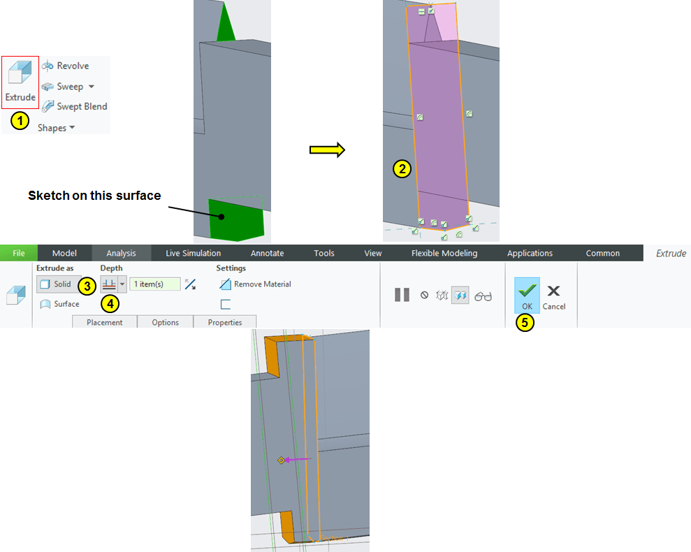
Click on Extrude icon and choose the surface available between blade and handle, sketch the shown profile and extrude it up to DTM1.
STEP 10.
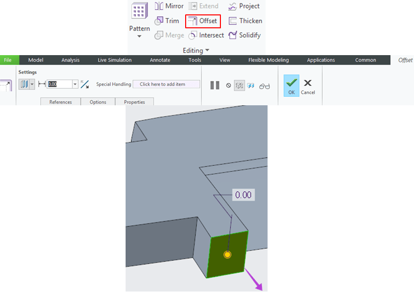
Create a new surface on the bottom using the Offset icon and keep it at 0 mm.
STEP 11.
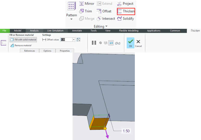
Thicken the previously extracted surface with 1.5mm.
STEP 12.
Remove the unnecessary surface created by the Thinken feature from the previous step.
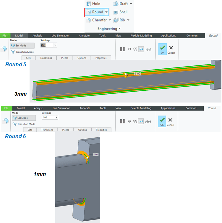
STEP 13.
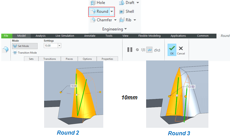
Add 2 Round features of 10mm as shown:
STEP 14.
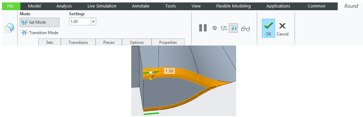
Add a Round of 1mm on the bottom side.
STEP 15.
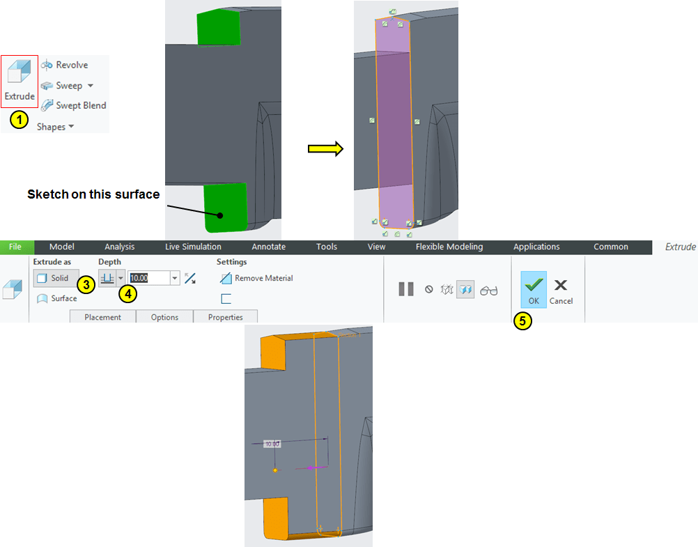
Add some extra volume on the surface between blade and handle. Click Extrude icon and sketch the profile as shown and extrude it 10mm.
STEP 16.
Add the last 2 rounds on the handle.
STEP 17.
Add steel appearance:
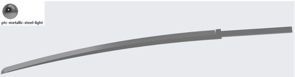
…and the Blade Design is now finished.
This assembly work is also available as video version on my YouTube channel as embedded below:

Leave a comment