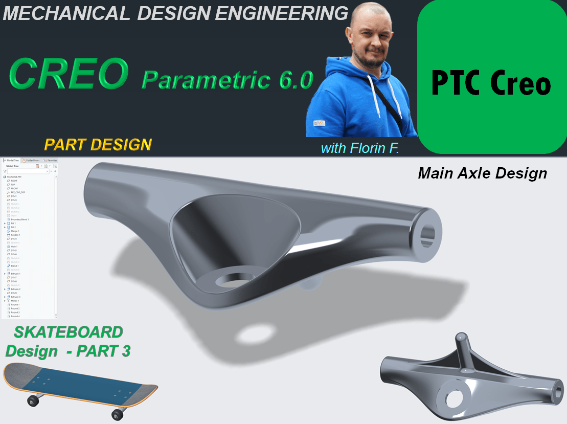
The design procedure of the Main Axle of a skateboard done with CREO Parametric goes as follows:
STEP 1.

Create a new Part and rename it Main Axle
STEP 2.

Create 2 new datum planes with an offset of 65mm from the Front Plane on each side.
STEP 3.
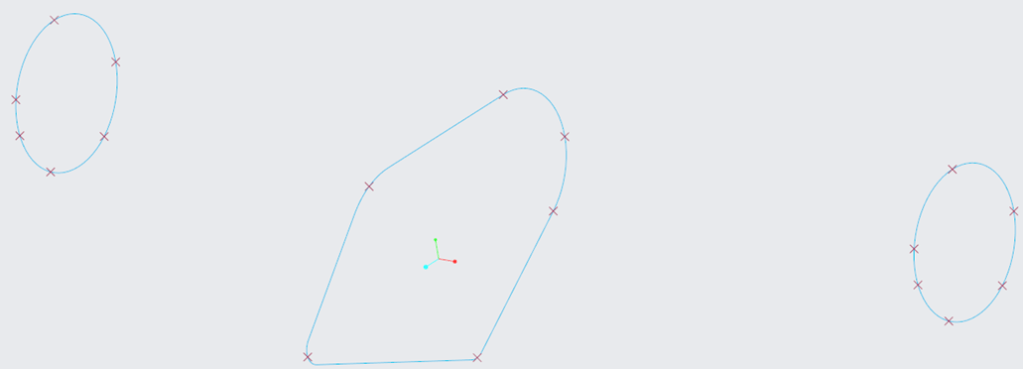
On Front Plane Create the following sketch including the 6 additional datum points as shown:

STEP 4.
On both Datum plane DTM1 and DTM2 create a sketch as shown:

After all the elements (profiles and datum points) are created in sketch environment, the result is this:
STEP 5.
On Surface ribbon, click on Style icon to enter the Style workbench and create 6 curves as shown:

After all 6 curves are created, click OK to exit the Curve Environment and click on Curve Edit icon to edit the tangency at the end points, as shown:

Just to see the comparision between the curves with default tangency vs. edited tangency, the wireframe has a better design for edited version.

Once the curves are correctly defined, in Style Workbench click the OK icon to return in Model Workbench and continue with the design work.
STEP 6.
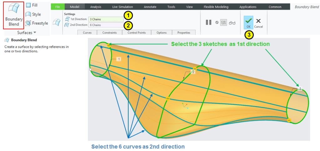
Create the surface that blends the wireframe boundaries. Click on Boundary Blend icon and do the necessay selections:
STEP 7.
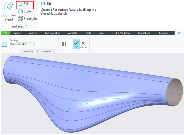
On both sides the previously created blend surface has open areas. Click on Fill icon and create a flat surface on each side.
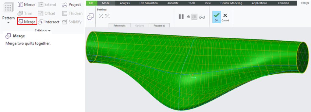
STEP 8.
Select all 3 created quilts and click on Merge icon to create a single element made of them.
STEP 9.
Keep the Merge feature selected and click on Solidify icon to add volume.

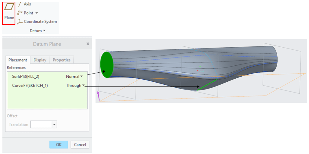
STEP 10.
Create a new Datum Plane having as reference one of the sidewise quilt and the bottom straight line from the middle sketch.
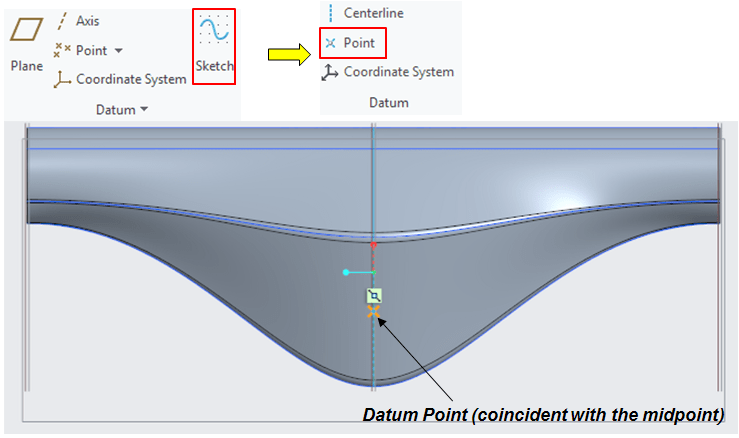
STEP 11.
On the previously created datum plane (DTM3), sketch a new datum point conicident with the middli point of the straight line.
STEP 12.
Use the datum point to create a hole with the following characteristics:

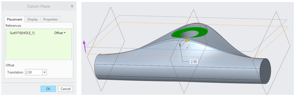
STEP 13.
Create a Datum Plane (DTM4) with an offset of 2,5mm downwards from the bottom of the counterbore.
STEP 14.
Create another Datum Plane (DTM5) with an offset of 25mm downwards from the previous Datum Plane.

STEP 15.
On Datum Plane DTM4 sketch a circle with the same diameter like the counterbore and divide it in 4 egual segments.

STEP 16.
On Datum Plane DTM 5 sketch an Elipse of 27mm width and 62mm length and divide it in 4 egual segments.
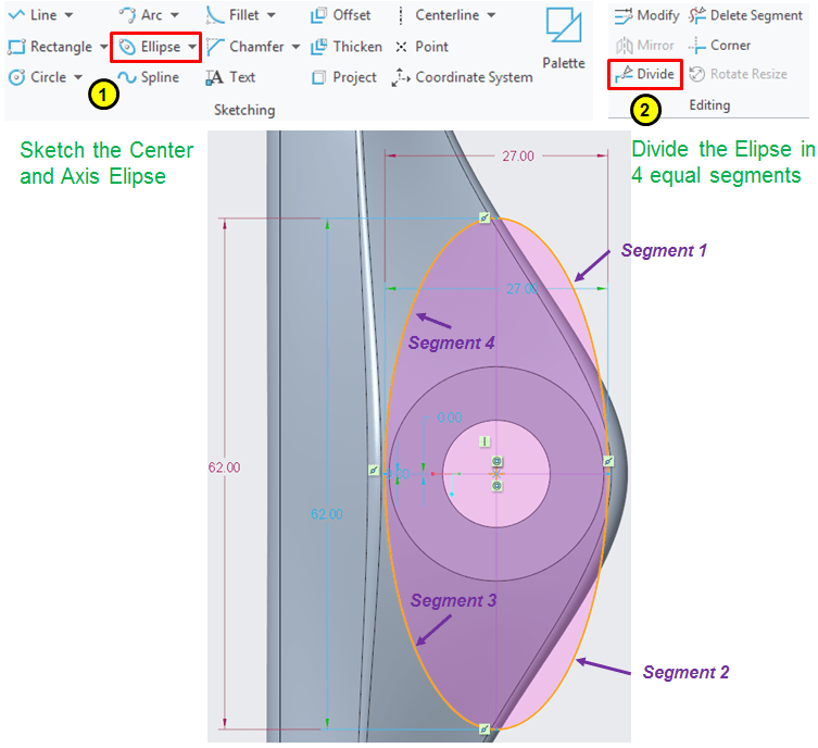
STEP 17.
Create a Blend between the circle from STEP 15 and the Elipse from STEP 16 as removed material.

STEP 18.
On one of the side surfaces create a sketch as circle for a Through All Extrude.
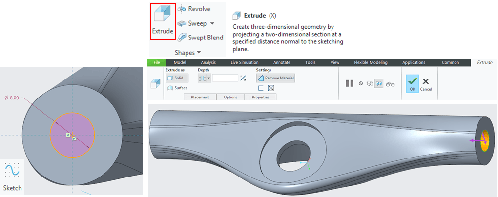
STEP 19.
Create a Datum Plane (DTM6) rotated at 12° around the Axle axis versus the Top Plane.

STEP 20.
Create the Datum Plane (DTM7) with an offset of 5mm from DTM6.

STEP 21.
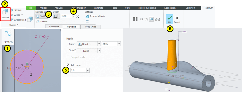
On datum plane DTM 7 (from STEP 20) first sketch a circle of 11mm diameter with its center point coincident with the origin point then extrude the circle upwards with 35 mm and add a taper of 2°.
STEP 22.
Create the Datum Plane DTM 8 rotated around Axle axis at 12° versus the Right Plane.

STEP 23.
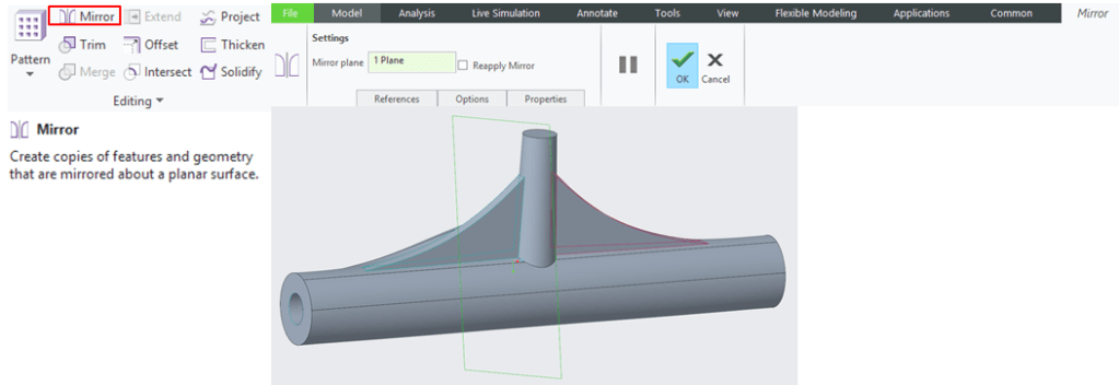
On Datum plane DTM8 create a sketch made of 2 lines and a spline, in the sketch mode first choose the right references then draw the sketch, define the constrains; exit the sketch mode and use this profile to create an extrude by mid plane of 3mm thinkness.

STEP 24.
Mirror the last extrude versus Front Plane.
STEP 25.
Add the radius of 1.25mm in 2 sets, set1 for 3 edges as circular and set 2 for 1 edge as conic with a 0,5 conic parameter.

STEP 26.
Add the final radius on edges as shown:
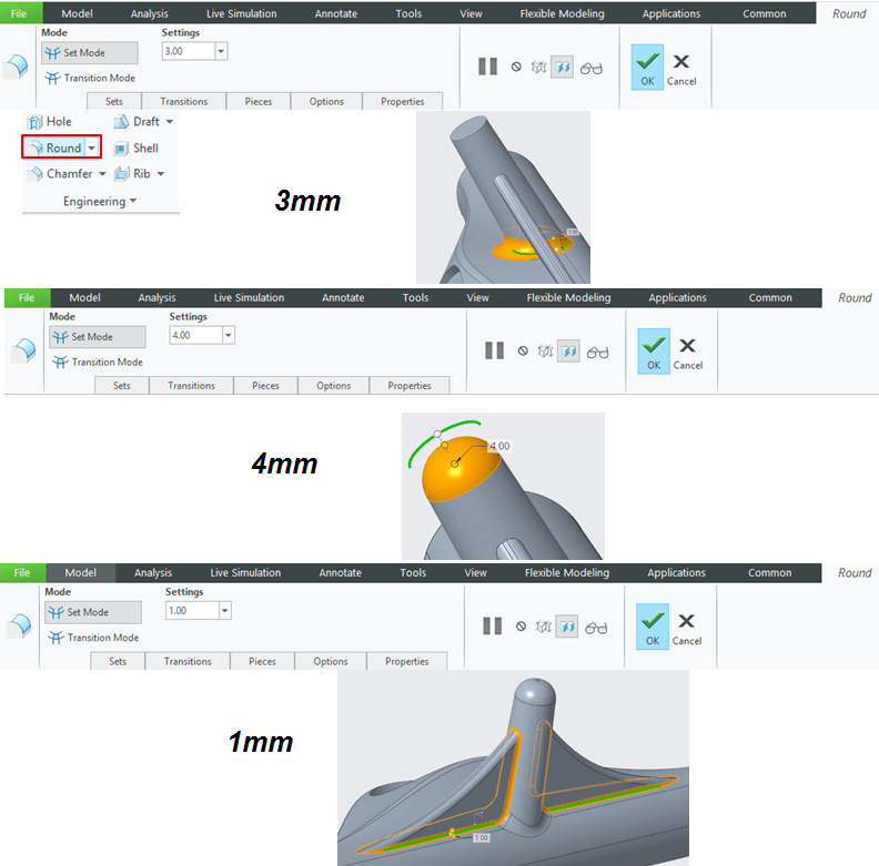
STEP 27.
Add appearance to make the part look more realistic.

The final design looks like this:

This design work is also available as video version on my YouTube channel as embedded below:

Leave a comment