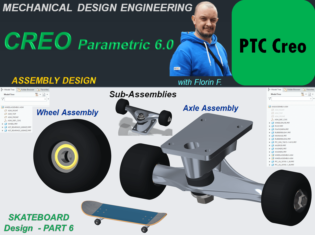
To create a product you must first design the component which are later put together in the final product assembly. But when every component is ready also it makes very much sense to group some components in a sub-assembly which will be part of the final one. Therefore let’s create the sub-assemblies necessary for the Skateboard product, namely The Wheel Assembly and The Axle Assembly.
THE WHEEL ASSEMBLY
STEP 1.

Create a New Assembly and rename it WheelAssembly.
STEP 2.
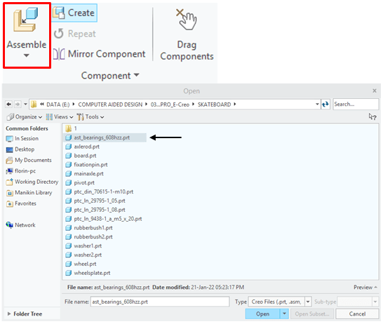
In Assemby Enviroment, click on Assemble Icon from Component ribbon, and browse for the part called Wheel in project folder, then click Open.

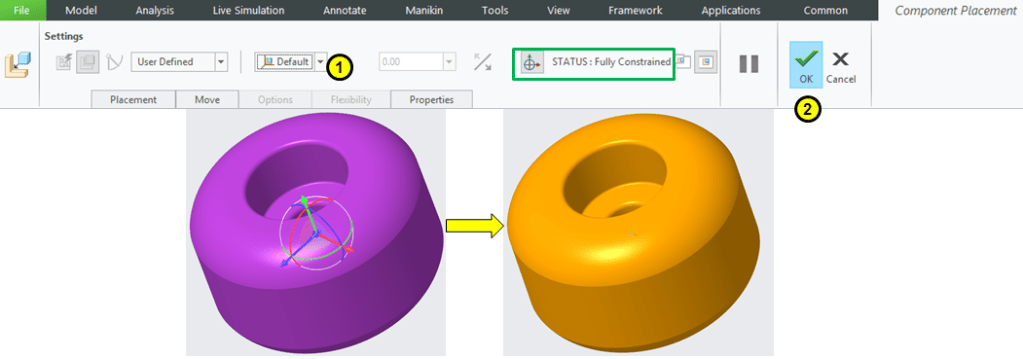
In Component Placement dialog box select the Default constraint and click OK. The Wheel is now the default reference in the assembly. Everything you add later will be refered to the Wheel position.
STEP 3.
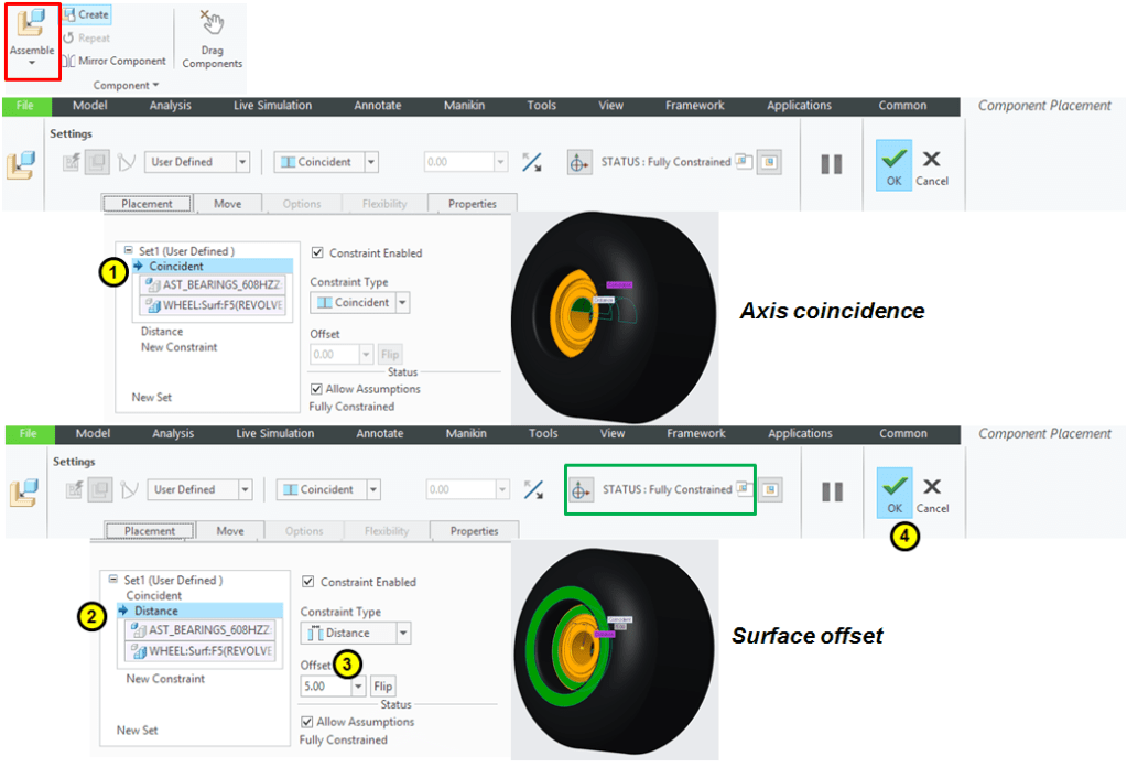
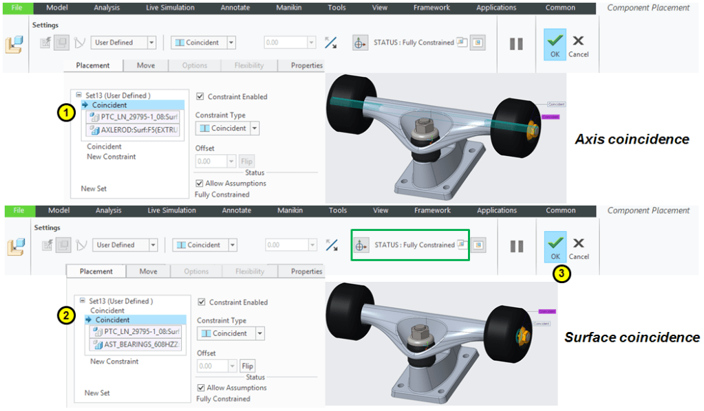
Keep clicking on the Assembly icon to add the rest of components. Add the 1st Ball Bearing and define the constraints as shown:
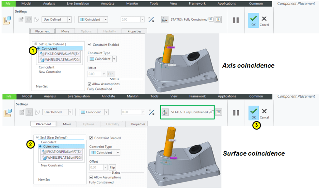
Always check the STATUS and make sure is “Fully Constrained” before to click OK.
STEP 4.
Repeat the procedure from STEP 2 for the 2nd Ball Bearing.
After everything is added and fully constrained the Wheel Sub-Assembly looks like this:

THE AXLE ASSEMBLY
STEP 1.
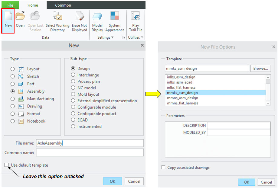
Create a New Assembly and rename it AxleAssembly.
STEP 2.
In Assemby Enviroment, click on Assemble Icon from Component ribbon, and browse for the part called Wheelplate in project folder, then click Open.
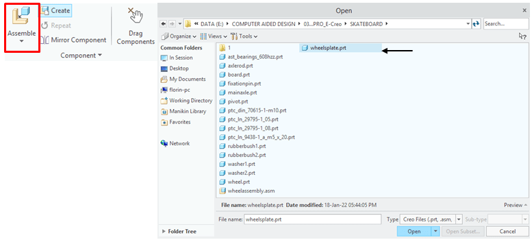
In Component Placement dialog box select the Default constraint and click OK. The Wheelplate is now the default reference in the assembly. Everything you add later will be refered to the Wheelplate position.

STEP 3.
Keep clicking on the Assembly icon to add the rest of components. Add the Pivot Part…
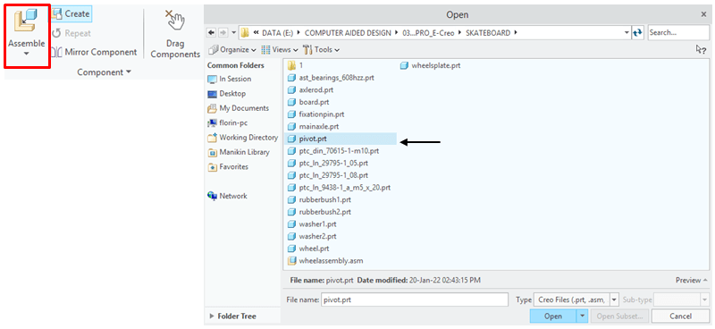
… and define the constraints as shown:

STEP 4.
Add the Fixationpin…

… and define the constraints as shown:
STEP 5.
Add the RubberBush1…
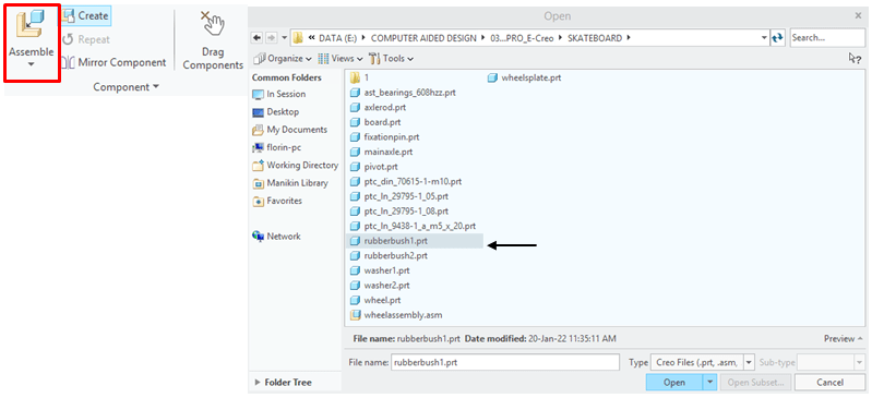
… and define the constraints as shown:

STEP 6.
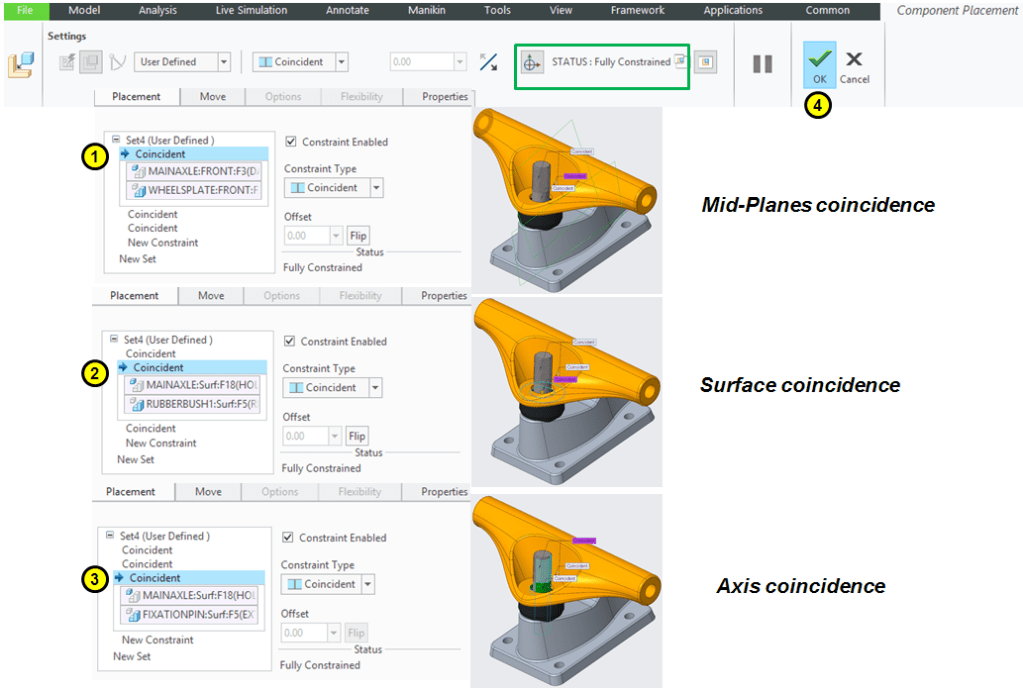
Add the MainAxle…
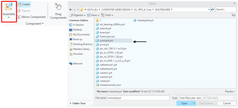
… and define the constraints as shown:
STEP 7.
Add the RubberBush2…

… and define the constraints as shown:

STEP 8.
Add the Washer1…
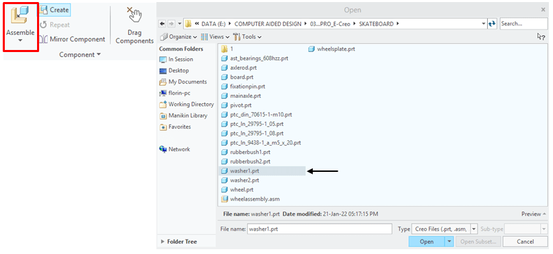
… and define the constraints as shown:

STEP 9.
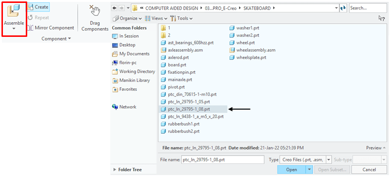
Add the Fixation M10 Nut …

… and define the constraints as shown:

STEP 10.
Add the AxleRod…
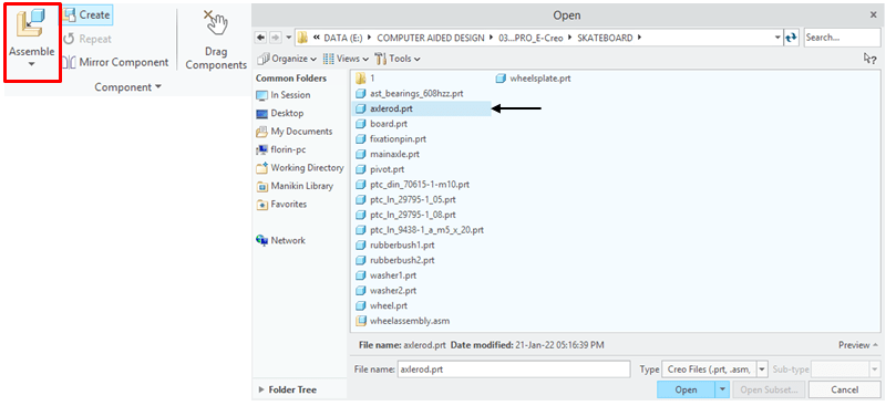
… and define the constraints as shown:

STEP 11.
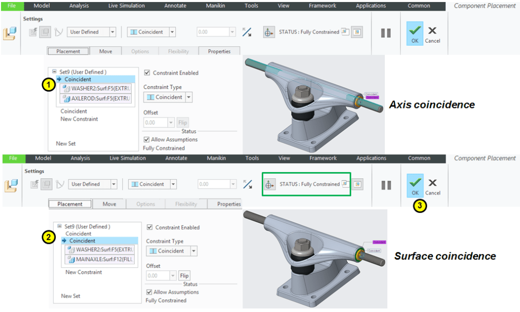
Add the Washer2…

… and define the constraints as shown:
STEP 12.
Repeat the procedure from STEP 11 to add the 2nd Washer2 on the other side.
STEP 13.
Add the 1st Wheel Sub-Assembly…
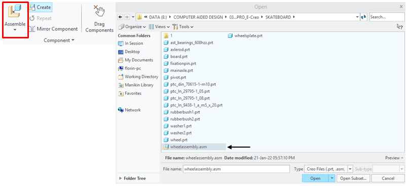
… and define the constraints as shown:

STEP 14.
Add the 2nd Wheel Sub-Assembly…

STEP 15.
Add the 1st M8 Nut…
… and define the constraints as shown:
STEP 16.
Repeat the procedure from STEP 16 to add the 2nd M8 Nut…
The Axle Sub-assembly is finished and looks like this:

This design work is also available as video version on my YouTube channel as embedded below:

Leave a comment