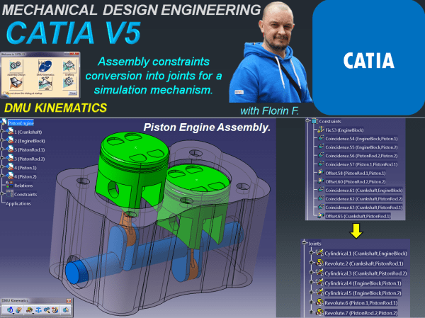
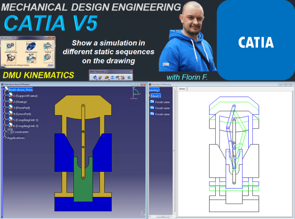
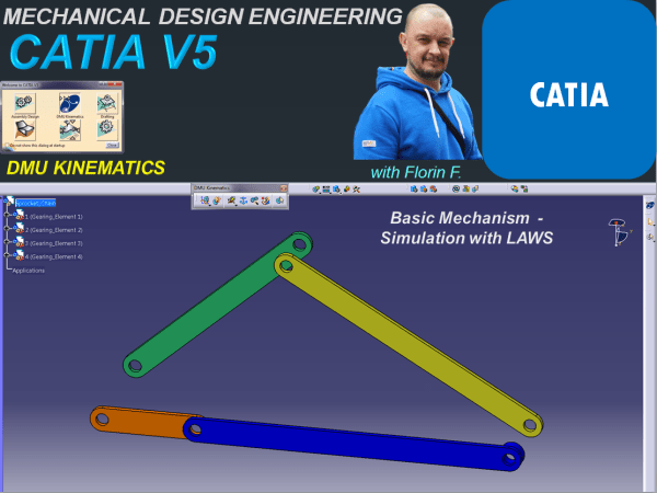
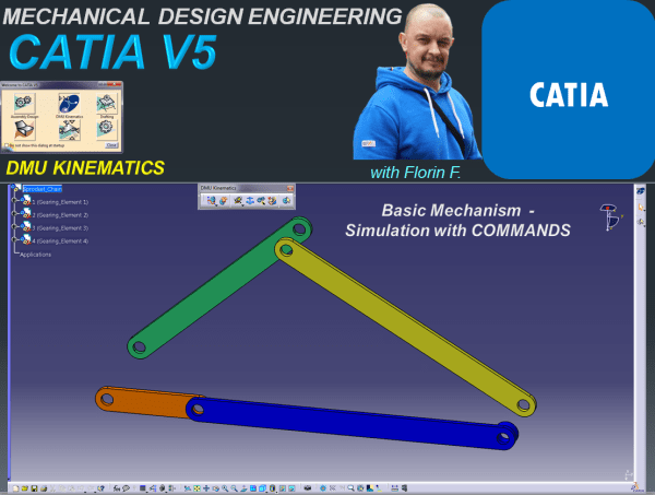
The best option to simulate a mechanism with CATIA V5 is of course by using the dedicated one named DMU Kinematics Workbench. But as CATIA is a very interactive and versatile CAD software some simulation can be also done in other workbenches. For example sketch animation is sometimes a very useful feature and this can... Continue Reading →
CATIA V5 _DMU KINEMATICS_Assembly constraints conversion into joints for a simulation mechanism.
In most cases when you want to do a mechanism simulation with CATIA V5, you perform this, using the DMU KINEMATICS Workbench where you initially prepare your assembly mechanism by only arranging the parts in an approximate position without defining the constraints. This is because in DMU Kinematics before to simulate your mechanism you must... Continue Reading →
CREO PARAMETRIC 6.0 – PART DESIGN_Revolved part
A very frequent type of feature used in mechanical design development is the Revolved feature. There are many common working approaches with the Extruded part but as we are dealing with a different shape in this post I will show you how specifiaclly a Revolved part is created with CREO Parametric 6.0. STEP 1: As... Continue Reading →
CREO PARAMETRIC 6.0 – PART DESIGN_Extruded part
In the past a job as mechanical designer was a little bit of more hard work to do becasue products were first drawn by hand using large sheets of paper and many hours to put all the technical and geometrical specification on it which then had to be used in production. Today things are completelly... Continue Reading →
CATIA V5 _DMU KINEMATICS_Generate a tracking line in a 3D simulation_WindShield Wiper
For this exercise I am gonna show you how to generate a tracking line in a 3D simulation which can be very useful in many situations. Let´s say for example the windshield wiper: You simulate its motion but you also want to see exactly the area in which the wiper moves. For this is very... Continue Reading →
CATIA V5 _DMU KINEMATICS_Clash detection in DMU Kinematics simulations_Hinge assembly.
It is often the case that you want to make sure your mechanism works properly without clashes between its component parts. DMU Kinematics offers you the possibility to check your mechanism during simulation and easily detect any possible clash that might occur when you put your mechanism at work. Actually this is a very simple... Continue Reading →
CATIA V5 DMU Kinematics_Show a simulation in different static sequences on the drawing.
In this post I will show you how can you present different simulation stages of a mechanism in few static sequences drawing. Obviously before to create a drawing you must have your 3D available. So let's create the mechanism first. For this exercise we'll do a simulation with basic design of a Hold Down Press.... Continue Reading →
CATIA V5 DMU Kinematics_Basic Mechanism – Compile simulation for Replay and export your file as video format.
After we have seen how a simulation can be done with CATIA DMU Kinematics; let's see how to replay it anytime we want to see it again. Or we can even generate multiple replays in case we want to see multiple simulations with the same mechanism. Additionally it is also possible to compile a simulation... Continue Reading →
CATIA V5 _DMU KINEMATICS_Basics Simulation with Laws
In my previous post I showed how the Simulation with commands works in CATIA V5. For this type of simulation there is no time related function versus the command value, therefore all what you need for this is to define a driven command, create the kinematic joints and simulate the mechanism by changing the command... Continue Reading →
CATIA V5 _DMU KINEMATICS_Basics Simulation with Commands
In order to generate a simulable mechanism in Catia V5 you need to define 3 basic things: Define a fixed part.Define a gear which will be driven by a command.Define the kinematic joints between the elements of your assembly. It can be the case, that in an assembly you might need to simulate more than... Continue Reading →