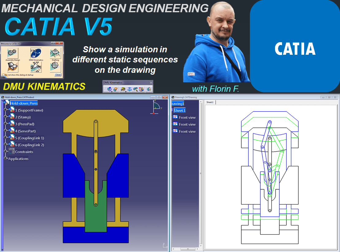
In this post I will show you how can you present different simulation stages of a mechanism in few static sequences drawing. Obviously before to create a drawing you must have your 3D available. So let’s create the mechanism first.
For this exercise we’ll do a simulation with basic design of a Hold Down Press. If you wish you can also Create the parts by yourself and then arrange them in an assembly more or less as shown (don’t put any constrains for now-that will be generated when we create the kinematic joints).
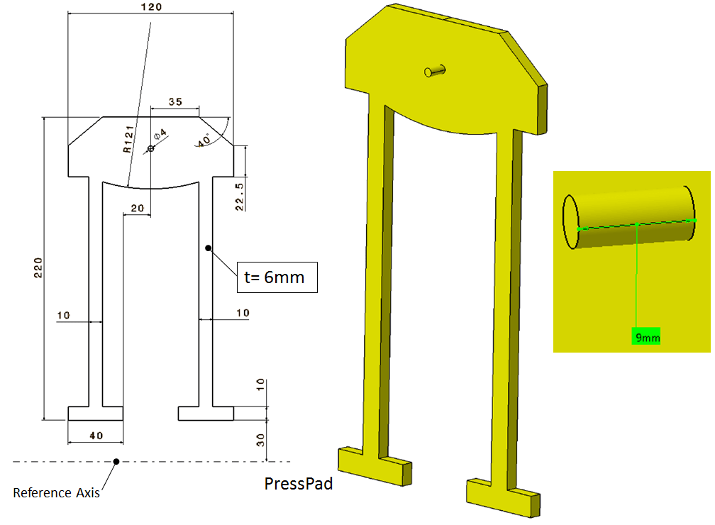
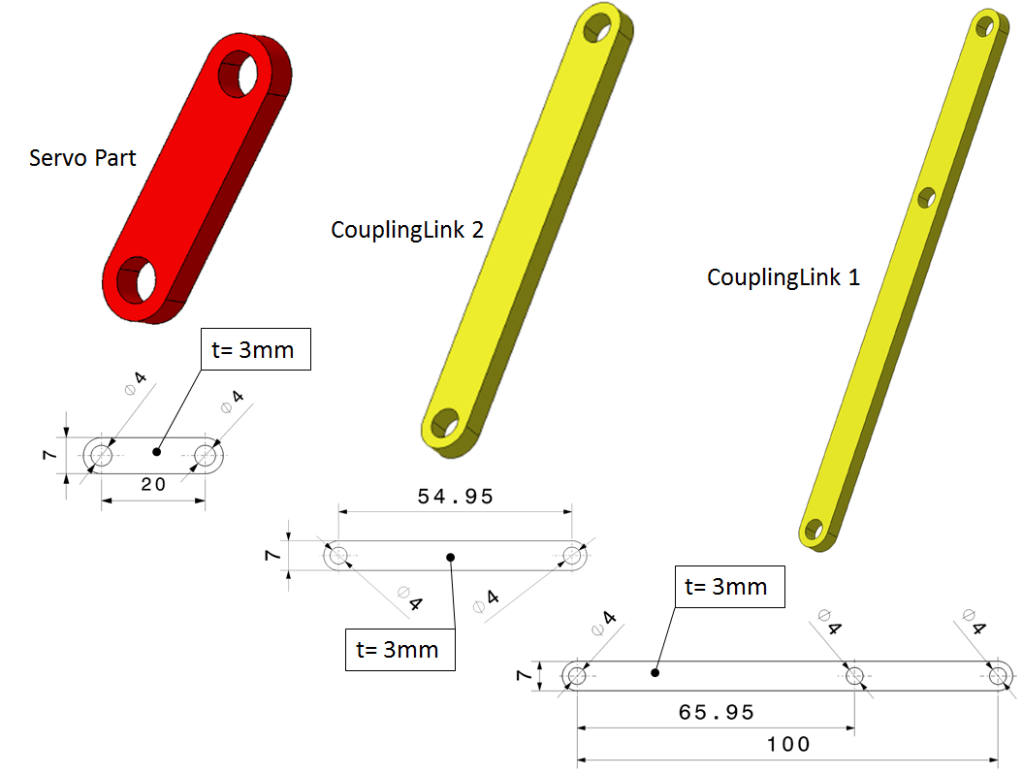
The 6 parts I used have the following geometry:


STEP 1.
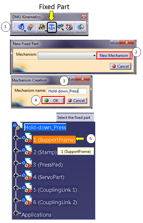
Once your assembly is ready for simulation let’s start by creating the mechanism and fix the reference part. On the DMU Kinematics toolbar click on the Fixed part icon and follow the settings as shown.
STEP 2.

Let’s create the necerassy Revolute Joints. On the Kinematic Joints toolbar, click the Revolute Joint icon and do the settings as show. For the first one tick on “Angle Driven” option too.

If you did you settings correctly Catia will inform you that “The mechanism can be simulated”. Click OK but don’t simulate anything yet. You must create all the kinematic joints first.
In this exercise we will need only 2 types of joints: Revolute Joint and Planar Joint.
Step 3.
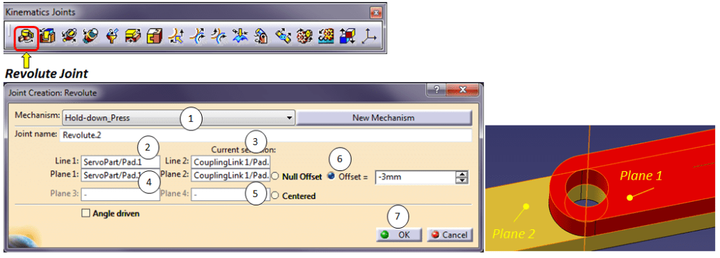
Continue with the rest as shown, Do it for Revolute Joint 2 between the ServoPart and CouplingLink 1
Step 4.
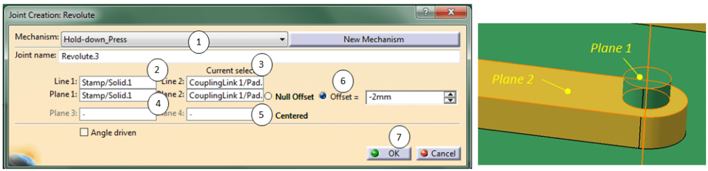
Revolute Joint 3 between the Stamp and CouplingLink 1
STEp 5.
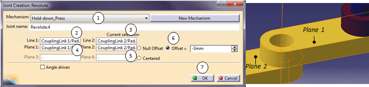
Revolute Joint 4 between the CouplingLink1 and CouplingLink 2
step 6.
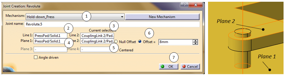
Revolute Joint 5 between the PressPad and CouplingLink 2
step 7.

Now continue with the Planar Joint.6 between the SupportFrame and Stamp
step 8.

Repeat Step 7. for PlanarJoint 7.
If you’ve done everything correctly Catia will inform you again that “The mechanism can be simulated”
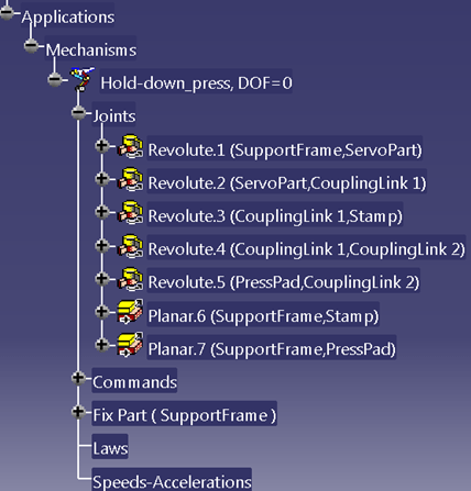
Everything is now added in the specification tree as shown. Simulation can now be created.
step 9.
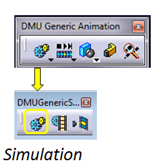
In the generic Animation toolbar click on the “Simulation” icon

In case the simulation object not already selected in the SpecificationTree, select it in this dialog box and click OK.
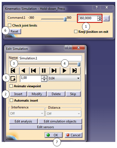
Of course you can be creative here and use as many simulation sequences as you want. Just do the settings for each of your prefered sequence in the shown order from Step 1 to Step 5. In this example I ‘ve used only one simulation sequence for the Command.1 at at 360°. So type the value, click Enter and continue with Step 2 until Step 5 , check the result and when you’re done proceed with step 6 and 7.
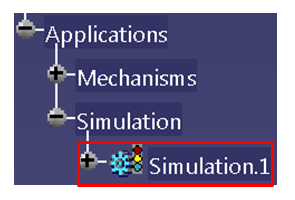
The simulation is created and available in the specification tree.
step 10.

Now once everything’s clear with the 3D let’s create the 2D and show the mechanism in different static simulation sequences. On the Standard toolbar, click on the Icon “New”

Do the settings as shown.
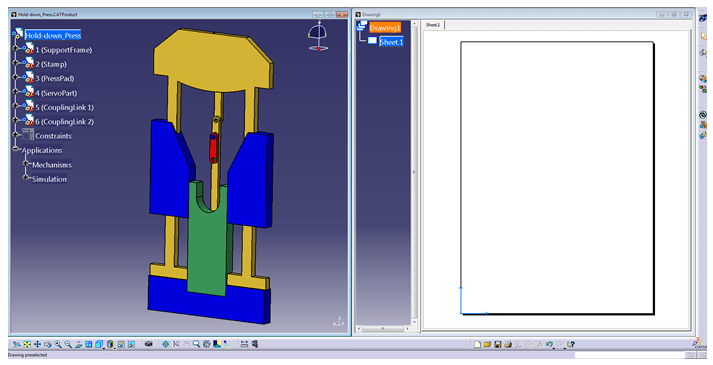
Your screen should be ready and look like this:
step 11.

While you are active in the Drawing, in the Views toolbar click on the “Front view” icon.
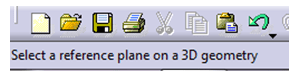
Catia will now ask you to select a reference plane on a 3D geometry.

Select the 3D reference plan and drop the view on the drawing. It should look like this.
By default CATIA will project your 3D on 2D at 1:1 Scale. But it can often happen that it could be too big. So in this case do a right click on the active view and from the drop down menu click on Properties and change the scale at 1:2 as shown.

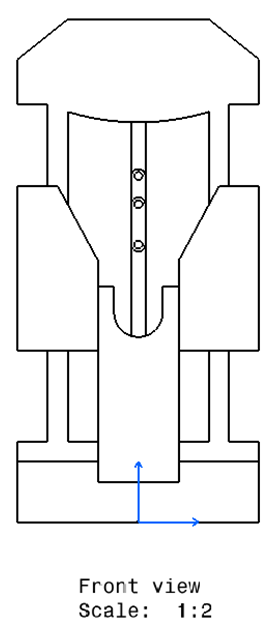
The part is now displayed smaller.
step 12.
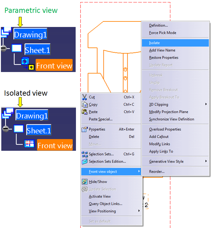
In order to show multiple static sequences of a simulation of one mechanism, you can do this by isolating the views you put on the drawing. So again, while on the active view right click on the ViewFrame (marked red) and from the drop down menu click on Isolate as shown.
step 13.
Let’s say you want to see the mechanism at command position = 0°, 120° and 210° and put that on a drawing. For this you must alternatively work with 3D and 2D.
In the 3D, click on the Simulation with command icon, and type 120 in the command value and close the dialog box. Create a new front view with this on 2D. Repeat the settings for the command value 210.

At the end you will put these 3 view on the drawing and isolate them as mentioned at Step 12.

step 14.
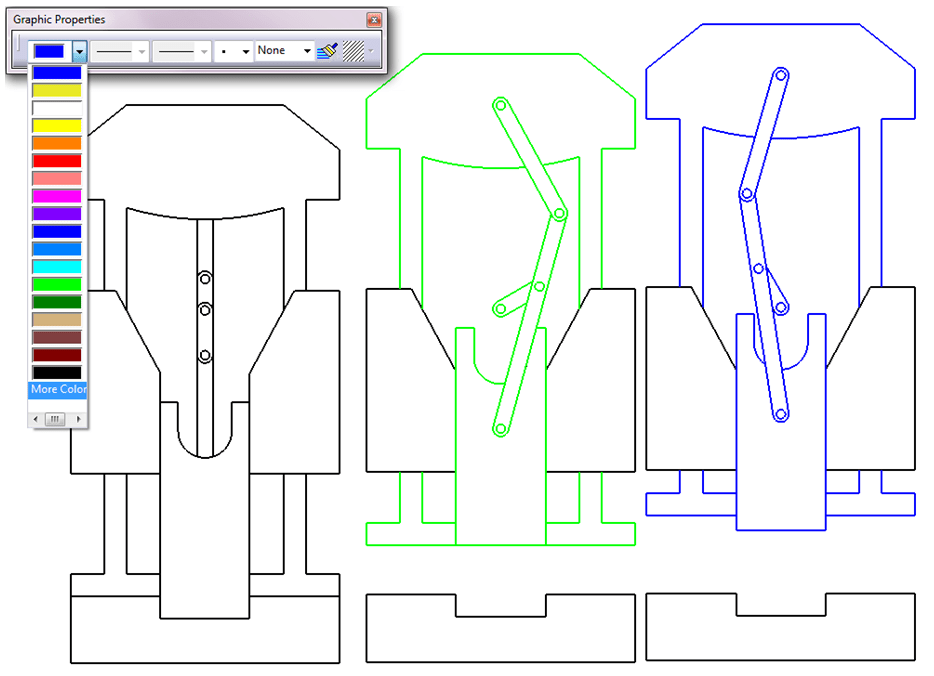
In the Graphing Properties toolbar it will be helpful to change the color for the mobile parts for example as shown:
step 15.
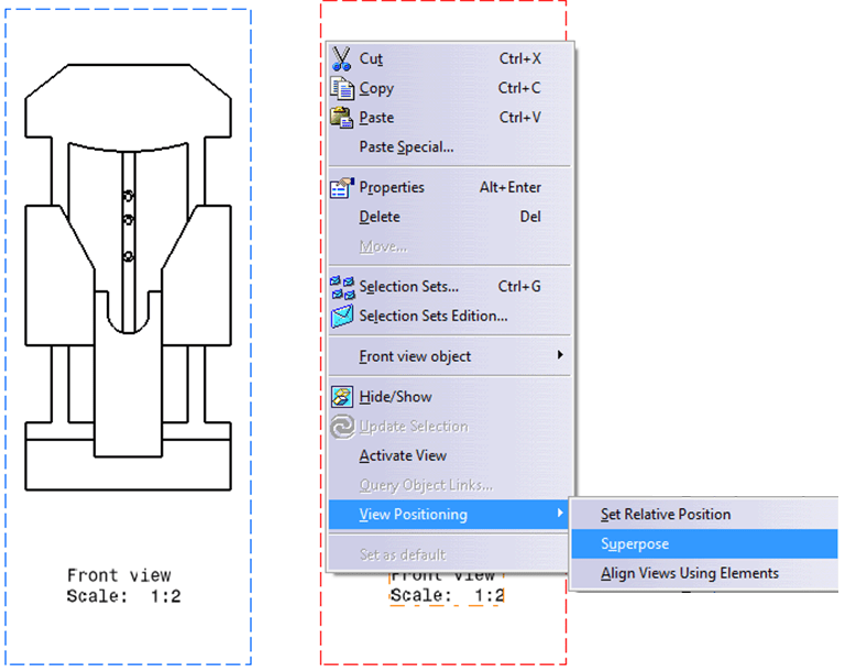
Now all what you have to do in oder to see the mechanim in its defined sequences is to supperpose all 3 views. To do this drag the main view (the one showing the mechanism at its starting point 0°) and superpose the other 2 over this main one; Right-click on the active view (red marked frame) and from the drop down menu choose “Superpose”
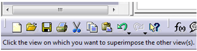
Catia will now ask you to point the view you want to superimpose other view(s).

…..and here you are, this is the result.
You can also follow this exercise in the video below.

Leave a comment