
For this exercise I am gonna show you how to generate a tracking line in a 3D simulation which can be very useful in many situations. Let´s say for example the windshield wiper: You simulate its motion but you also want to see exactly the area in which the wiper moves. For this is very useful to generate a tracking line which makes the view clearly defined, and then it can also be helpful to show this in a 2D drawing. Let´s start.
The template assembly I use in this exercise is made of 6 elements and in its initial state looks as shown below.

If you wish, to try this from scratch, you can create the elements by yourself and at the end just arrange them in the same way as just shown without putting any constraints. The constraints will be automatically generated when we will define the joints between the components.
Element 1 = The Frame

Element 2 & 3 = Transmission element 2 & 3
Element 4 = Transmission element 4
Element 5 = Transmission element 5
Element 6 = Transmission element 6
Now let´s proceed with the 3D simulation first.

Once your assembly is ready, open the file…

As usual, the first thing to do when you create a simulation is to define the fixed part. In the DMU Kinematics toolbar, click the icon “Fixed part”

Follow the settings as shown in order to define the fixed part, which is the 1st Element (Frame)
Then you can proceed with joints definitions. The 1st one is a Revolute joint between The Element 1 (The Frame) and the Element 2 (Transmission Element 2). Do the settings as shown below:

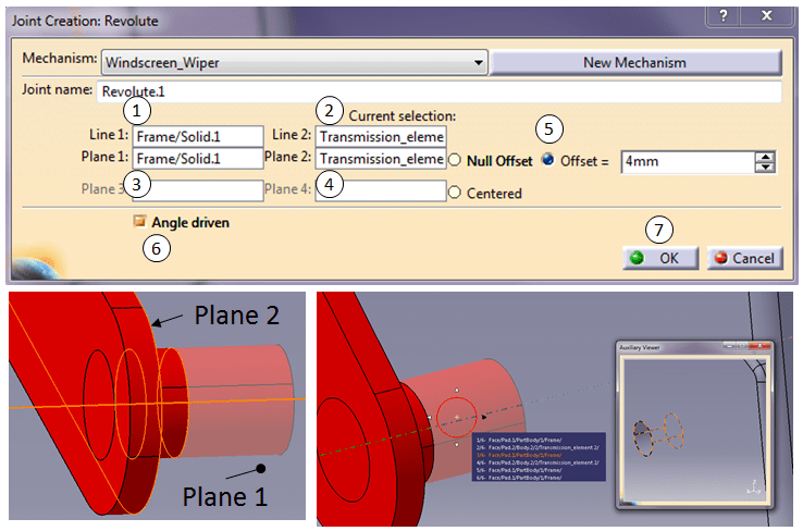
When you select the axis for the Frame you can either hide the Transmision element 2 (red part) in the SpecTree or there is an additional tool that can help with this, which is not shown by default and is pretty useful. Simply check “Display auxiliary viewer for preselection navigator” in the options panel (Tools > Options > General > Display > Navigation), as shown in the dialog box below.

Now when you use the up/down arrow keys from the keyboard, a small graphics window is shown which displays just the component that owns the currently highlighted element, updating as you scroll through the list. You can navigate within this window, spin, zoom etc. to be sure you accurately identify the precise entity you wish to select.

After you´re done with the 1st joint, Catia already informs you that “The mechanism can be simulated”, just click OK, don´t simulate anything yet. Continue the joint definition until all joints are complete.

Create the 2nd joint (Revolute.2) between the Element 2 and Element 3.

Create the 3rd joint (Revolute.3) between the Element 3 and Element 4.
Create the 4th joint (Revolute.4) between the Element 4 and Element 1 (The Frame).


Create the 5th joint (Revolute.5) between the Element 4 and Element 6.

Create the 6th joint (Revolute.6) between the Element 5 and Element 6.
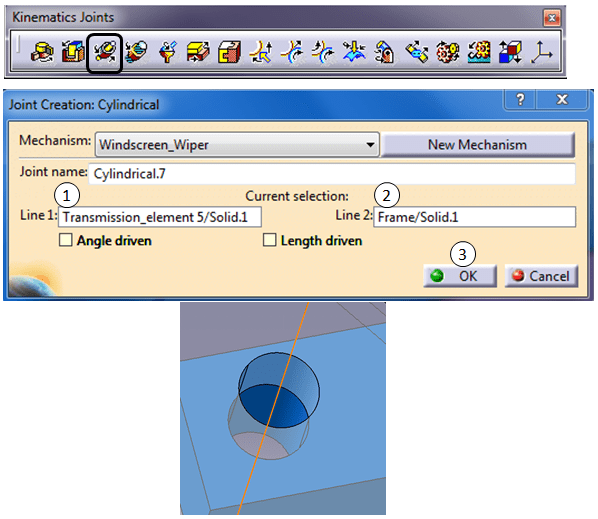
Create the 7th joint (Cylindrical.7) between the Element 5 and Element 1.

Catia now informs you again the mechanism ca be simulated.
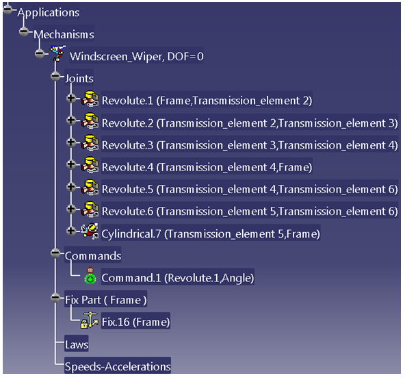
All the defined joints are added in the Specification Tree.

In the DMU Generic Animation toolbar click on the simulation icon, select the simulation object and click OK.

Do the settings from step 1 until Step 4 and check if everything works as expected. If yes, continue until step 7 and close both dialog boxes.

The simulation is created and added in the specification tree.

You can also generate the replay. For a better accuracy of your tracking line I suggest you to choose the smallest Time step (0,02 usually works well, but if that´s not as you expect then put the minimum at 0.01)
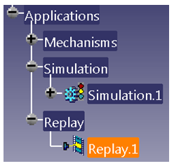
Which is added to Specification Tree accordingly.
Now once the simulation is correctly done and working we can proceed and create the tracking lines. In the DMU Generic Animation toolbar, click on the Trace icon as shown below and follow the settings accordingly.
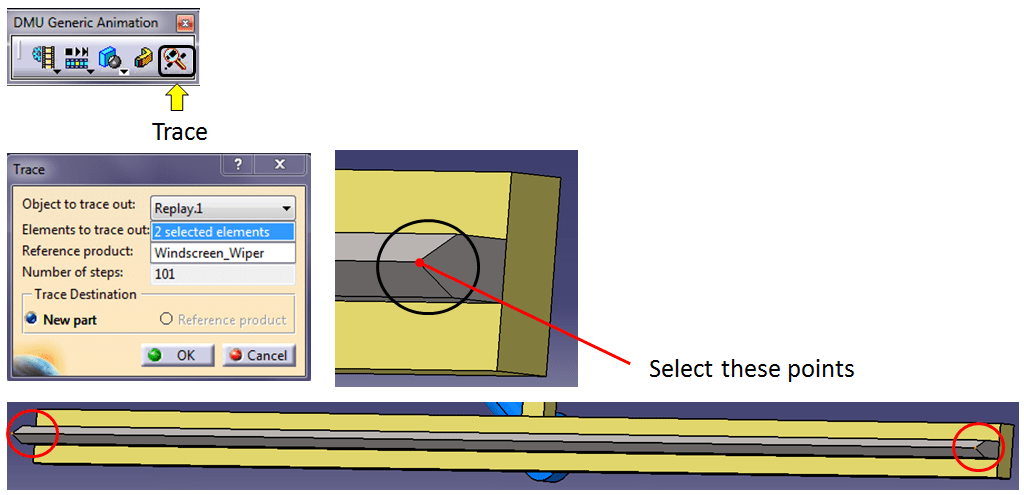

After you click ok in the Trace dialog box, Catia generates a new WireFrame Part called by default Trace1.CATPart which show the trajectory lines of the wiper motion.
Stay on this new Catpart and create 2 more additional lines using the Part Design workbench as shown below:

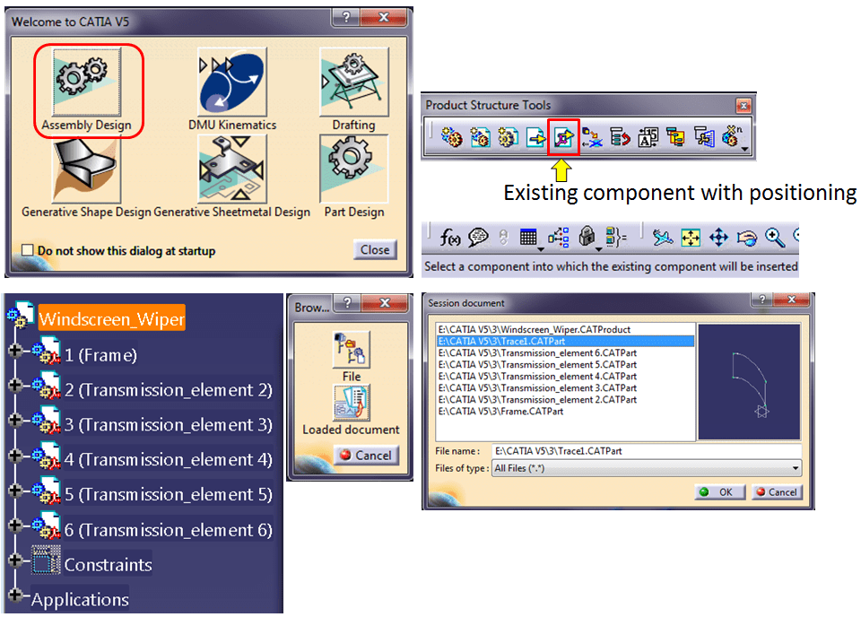
After the 2 additional lines are created, put all the generated points on hide mode and don´t forget to save the Trace1.CATPart. And then Switch to Assembly Design workbench.
In the Assembly Workbench click on the “Existing component with positioning” icon and then in the Browse dialog box click on the “Loaded document” icon, select the Trace1.CATPart and click OK.
In case you didn´t save yet the Trace1.CATPart and you still want to proceed Catia won´t add anything and it will warn you to save it.

Like that you have added in your simulation assembly also the trace lines showing the area in which the wiper acts. The only remaining thing is to also show this on the drawing. This is very simple task.
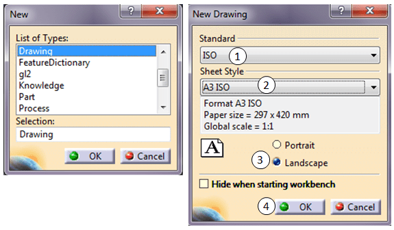
Just create a new drawing (or open the existing one where you wish to show the tracking lines).
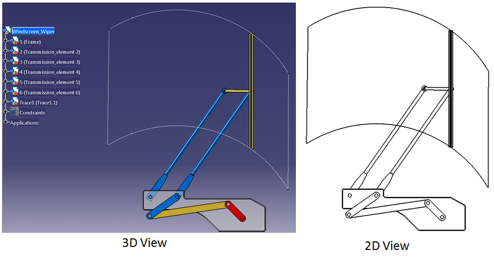
Click on the Front View icon to create a new view and then chose the front plane, for example the perpendicular view on the element 1 (The Frame). By default Catia creates a view at 1:1 scale. If that´s too big, click on the active view frame, go to properties and change the scale to 1:5

The result in 3D and 2D will look like this:
You can also follow this exercise in the embedded video as follows:

Leave a comment