In most cases when you want to do a mechanism simulation with CATIA V5, you perform this, using the DMU KINEMATICS Workbench where you initially prepare your assembly mechanism by only arranging the parts in an approximate position without defining the constraints. This is because in DMU Kinematics before to simulate your mechanism you must define the proper joints which in turn create the necessary set of constraints afterwards.
But what if your assembly has already all the parts fully constrained and you wish to try a simulation with it? Should you delete all the constraints and define them again when you create the joints in DMU Kinematics? Of course NO. If the constraints in your assembly are fully and correctly defined, NO need to delete anything to make it useful for DMU Kinematics. You can easily convert the defined constraints in DMU anytime later in case you wish to simulate your mechanism. In this post I show you How does this work.
Mechanism used in Assembly Design Workbench
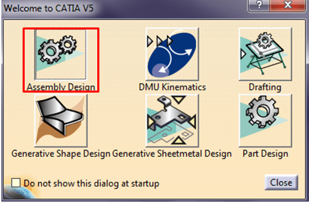
Assemblies in CATIA V5 are usually created and used in Assembly Design Workbench. So, activate this and let´s see how this can be useful to manipulate parts.
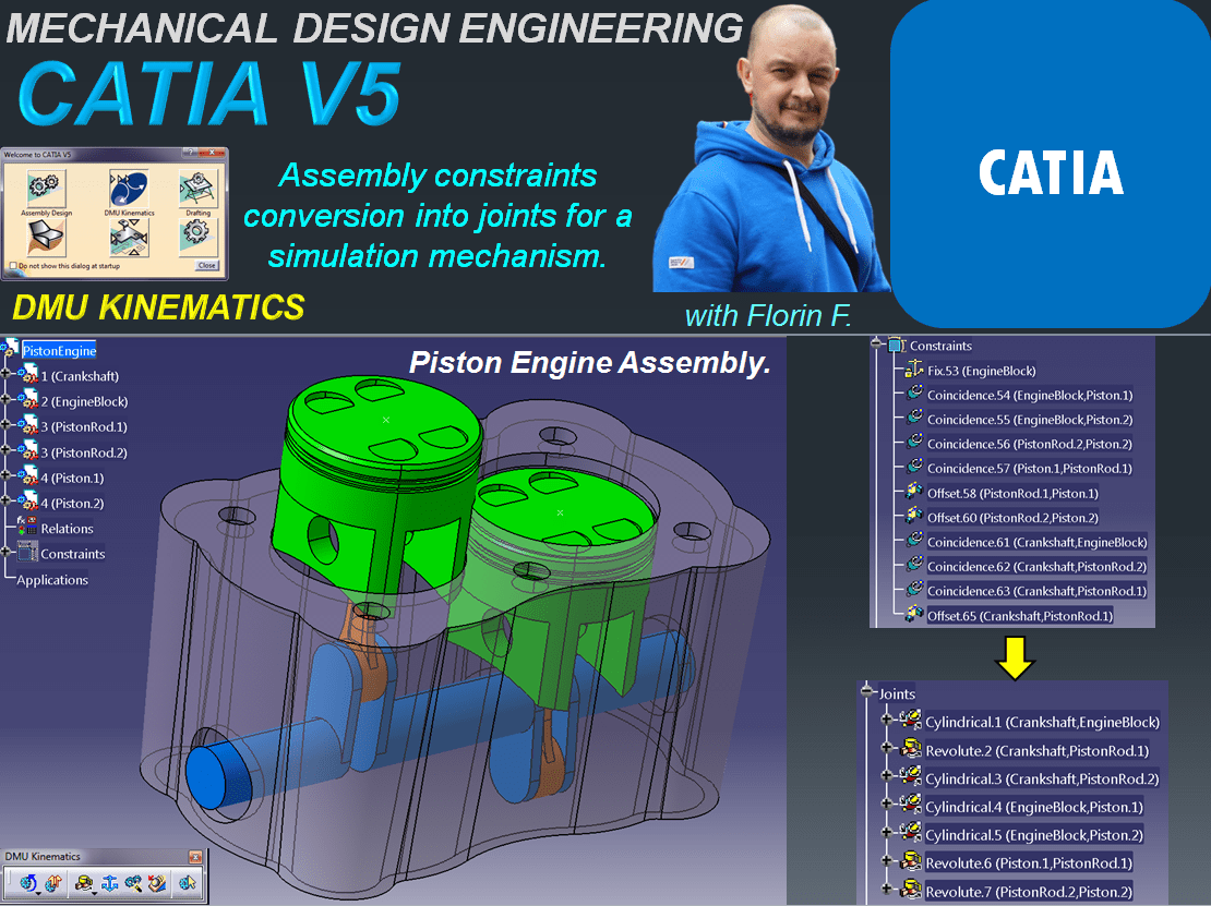
For this example I already have my PistonEngine Assembly fully defined as shown:

In Assembly Design Workbench once all the component parts are constrained, in case the designer wish to see a quick mechanism simulation, the component parts of the assembly can be easily manipulated anytime later.

To do this, just click on “Manipulation” icon in Move Toolbar and choose the direction in which you wish to manipulate a part. If the move must be in respect with the defined constraints just keep this option selected and manipulate the part as shown. In this example I rotate the Part CrankShaft (blue part) around Y axis.
Mechanism used in DMU KINEMATICS Workbench

However for a proper mechanism simulation you must put your assembly into DMU Kinematics Workbench.
This time you can create a Simulation based on the previously defined assembly. So for this, keep the Assembly open and just switch from Assembly Design Workbench to DMU Kinematics workbench. On the DMU Kinematics Toolbar click on the Assembly constraints conversion icon and do the settings as shown below:
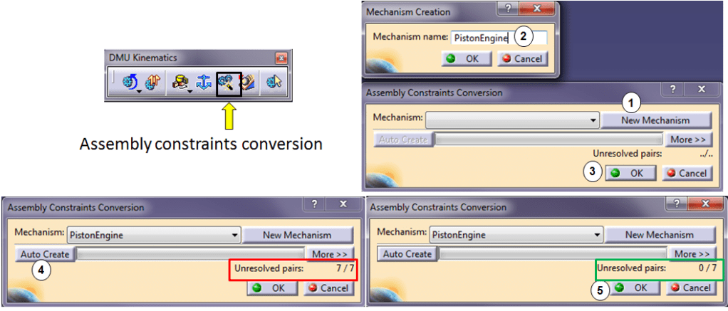
At step Nr.4 Catia tells you that 7 new joints will be created for this assembly, click Auto Create and then Click Ok.(Step 5).
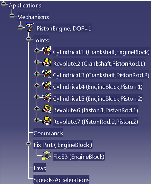
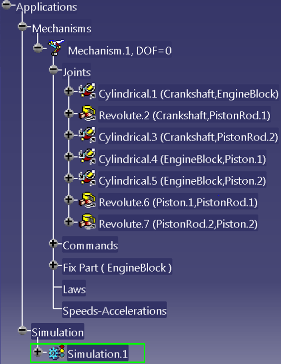
All the new joints are now available in the Applications Tree Structure. The fixed part is the one that was already fixed in the assembly before to use it in DMU. In my case here it´s the part EngineBlock.
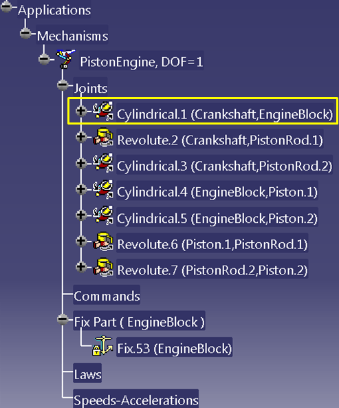
The conversion is done but this is still not sufficient to perform the simulation. You must also define at least a command. For this assembly the command is to rotate the Crankshaft around its axis. Therefore I make a double click on the 1st Joint named Cylindrical.1
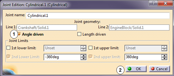
Then do the necessary clicks as shown and done.
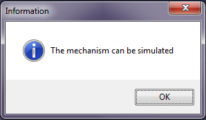
A short Information is displayed telling you that everything is ok.
The next step is to perform the simulation. In the DMU Generic Animation toolbar, click on Simulation icon and do the settings as shown:
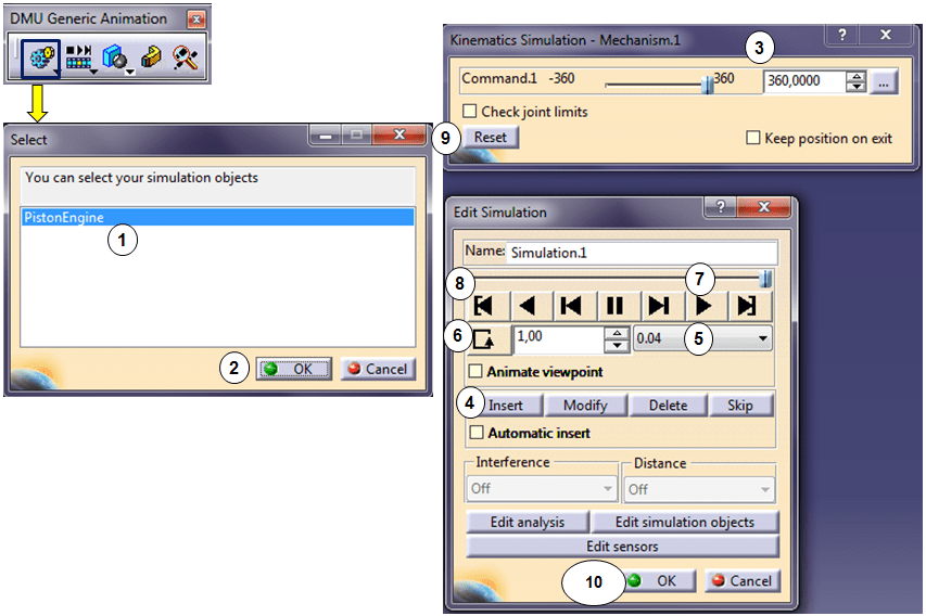
If the result is the expected one, after you click OK the Simulation is added in the Application Tree and available again anytime later.
You can also follow this exercise on my YouTube Channel as follows:

Your words have a way of paint vibrant images in my mind. I can imagine everything you portray.
LikeLike
That’s exactly what I am trying to do. I am glad to know you enjoy reaiding my stuff. Thank you so much.
LikeLike