
It is often the case that you want to make sure your mechanism works properly without clashes between its component parts. DMU Kinematics offers you the possibility to check your mechanism during simulation and easily detect any possible clash that might occur when you put your mechanism at work. Actually this is a very simple excercise but extremelly useful. In complex assemblies I highly recommend to do it with clash detection feature activated. Let´s see how this works below.
My assembly is already prepared so the from File Menu I click “Open…”
The assembly I use here is a hinge type, often used for different sort of mobile modules (maily for doors). To begin of course you must already have the CATProduct data available and parts freely arranged as displayed below.

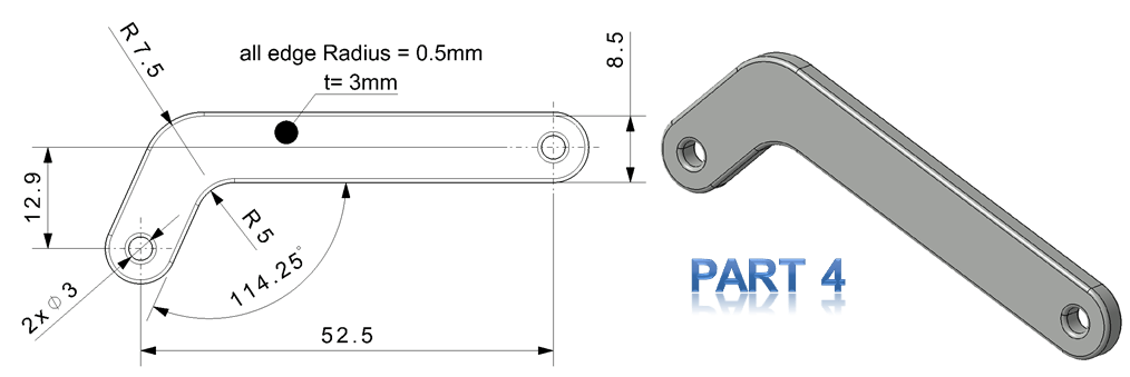
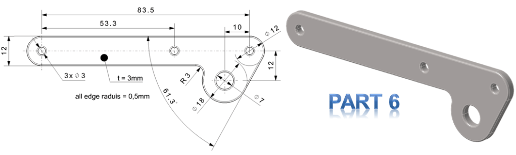
If you want you can create your own assembly as well, by creating the individual parts as follows:


Before to simulate anything, as usual you have to define the fixed part. For this, just follow the steps as shown
Continue with all joints definitions. Start with the 1st joint as Revolute Joint between Part 1 and Part 5, follow the steps as shown.
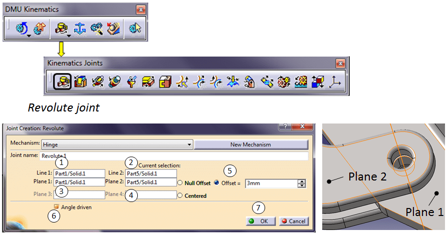

After the 1st joint definition Catia informs you that the mechanism can be simulated. Just click OK and continue with the definition of the rest of the joints.
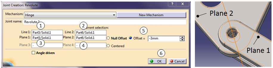
Create the 2nd joint as Revolute between Part 5 and Part 6.
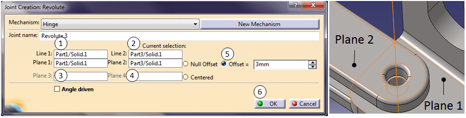
Create the 3rd joint as Revolute between Part 1 and Part 3.

Create the 4th joint as Cylindrical between Part 3 and Part 6.

Create the 5th joint as Revolute between Part 3 and Part 4.

Create the 6th joint as Revolute between Part 4 and Part 2.

Create the 7th joint as Cylindrical between Part 2 and Part 6.

When all joints are done, Catia informs you again that you can simulate. All the created joints are also available in the Specification Tree.
Do the simulation as follows:

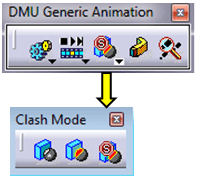
Just for info: The same clash mode options are also available in DMU Generic Animation toolbar (but not really useful for this exercise).
Pay attention to the Number of steps as shown at setting 2, the bigger the number the slower the motion is. If 200 is to slow, try with 80, or even 40 or 20 or lower. Before to play the simulation at setting 7, you can eventually change the values in the slider command.1 dialog box as shown at setting 5. Modifiy the value at setting 6 and give it a try by clicking play as shown at setting 7. Don´t close any dialog box until you are satisfied with what you see. When a Clash is detected the simulation is stopped and the area where the clash occurs is highlighted with red lines as shown in the screenshot above. The simulation can will only continue if you modify the parameters. You can play with it as much as needed, and before to close the dialog boxes don´t forget to click the Reset Button as shown at setting 8 and DONE.
You´ve successfully performed a clash detection in DMU Kinematics.
There is also another way to check assemblies for clashes but this is mostly a basic check and is done in Assembly Design Workbench, yet the principle is similar with the DMU Kinematics simulation case as just shown above. With the same assembly you can try it out as well. Switch to the Assembly Design and in the Move toolbar activate both icons for “Manipulation” and “Stop manipulate on Clash”, do as shown below and try to move the parts manually. When a clash is detected Catia will highlight the part in collision as shown in the screenshots below.

You can also watch this Clash Detection Simulation exercise on my YouTube Channel at the link embedded as follows:

Leave a comment