
In order to generate a simulable mechanism in Catia V5 you need to define 3 basic things:
- Define a fixed part.
- Define a gear which will be driven by a command.
- Define the kinematic joints between the elements of your assembly.
It can be the case, that in an assembly you might need to simulate more than one mechanism. But no matter how many mechanisms you need to simulate with your assembly, you always MUST to do the 3 basic settings as just mentioned.
Depending on the type of mechanism you want to simulate, you can have of course multiple driven commands between the parts in your assembly, but you must always define at least one driven command for the main gear which will generate the motion between the parts, otherwise your mechanism won´t be simulated. However try to not load your assembly with too many driven commands. In many cases 1 driven command is sufficient.
In this post I will show you the basics, you can anytime use this material, to practice your skills with DMU Kinematics in Catia V5. In my future I posts, will show you more complex simulations in, but for now let´s do the basics.
Before to start, I just want to tell you that with Catia V5 you there are 2 different simulation modes possible, as follows:


In this simulation mode the mechanism can be directly simulated by changing the values of the defined command(s) directly in its dialog box. By using „Simulation with commands“ there is NO dependent function between Command(s) and TIME.

In this simulation mode there is a dependent function between command(s) and TIME, and this can be simulated in Catia by using rules and formulas as motion laws. Your mechanism can be simulated by playing with speed and acceleration and you can even set different simulations for the same mechanism applying different laws.
That being said let´s do first the exercise applying the “Simulation with Commands” mode. For this I assume you already have the basic knowledge in Catia for Part and Assembly Deign workbenches, so before to create the simulation mechanism you must define your Parts and then put them into an assembly (without putting any constraints between the parts).
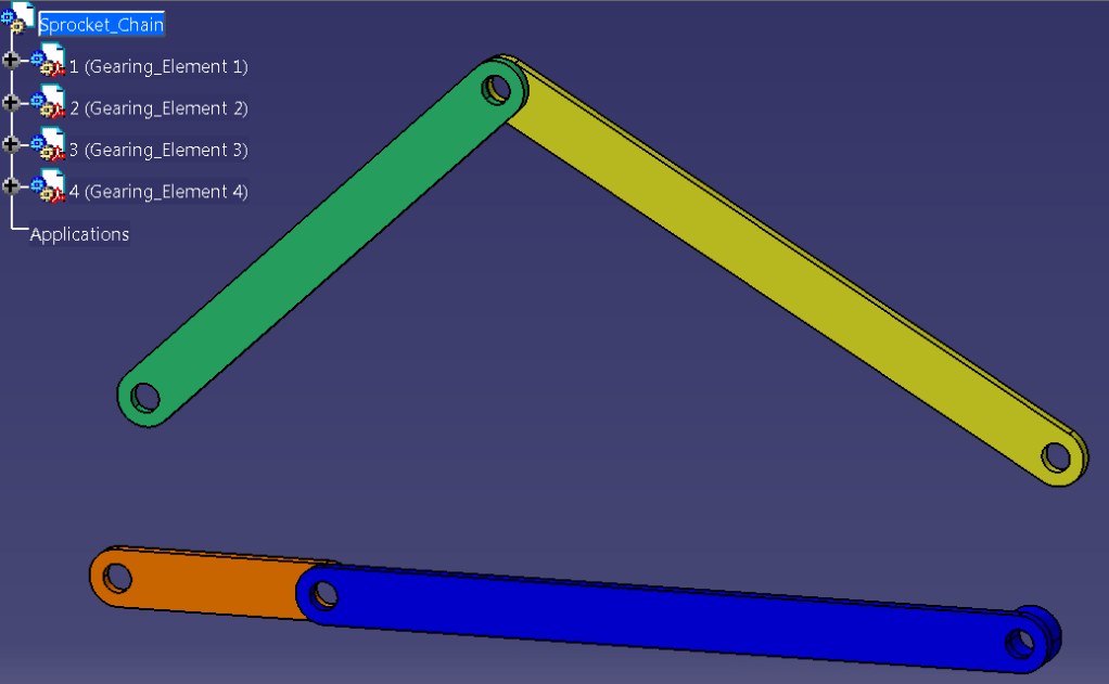
Let´t call our assembly: Sprocket Chain. To have the mechanism for that, just create the 4 parts as shown:

Once you have the parts, put them into an assembly and save it approximately as shown below:
Now let´s create first the mechanism and finally the simulation.
Step 1.

Once you have saved your assembly and it´s still open you can directly proceed. If you´ve closed it Open the assembly data: “Sprocket_Chain.CATProduct” again and put it in the DMU Kinematics Workbench. Your screen should look like this:

Step 2.

In the DMU Kinematics toolbar click on the Fixed Part icon and define which component you want to fix in order to create a simulable mechanism.

In the opened dialog box click on “New Mechanism” button.

By default Catia generates the new mechanism as “Mechanism.1”, you can either keep it or rename it as you like (my recommendation here is to give it a proper name – it will really help in case you will work with multiple mechanisms) and click “OK”.

After you click OK on Mechanism Creation dialog box , Catia informs you in the status bar that you must now select the part you wish to fix.
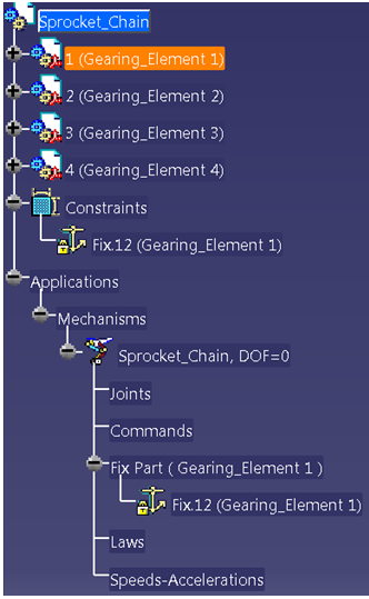
Go ahead and click on the part of your choice. In this exercise we choose the 1st gearing element (the blue part) either by selecting it in the SpecificationTree or directly pick it in the geometrical view.
The constraint is then automatically created both under the Constraints tree and Applications tree as shown.
Step 3.
Now you can start creating the kinematic joints between the components. You MUST pay attention how you do this, I would NOT recommend to do it randomly. For an efficient workflow you must follow an order in which you connect the parts. Always start by connecting your next element to the previous one taken as reference. You must follow a sort of serial connection.
In our example we have an assembly made of 4 parts. Because the Gearing Element 1 was already chosen to be the fixed one, we will connect the other 3 parts to this one on in a successive order. The parts are already arranged in this way in the SpecificationTree, so the order is already defined, we just need to create the joints. We take one after another.
For this CATIA offers you a lot of options to create simulation joints as shown in the “Kinematics Joints” toolbar.

On the DMU Kinematics toolbar, if you click on the little black arrow attached to the “Kinematic Joints” icon, CATIA will show you different possibilities to create Joints (currently 17 different types of Joints). I will show all these in detail in my future posts related to DMU Kinematics with CATIA, but for now we will only use 2 of them. The Revoute Joint and The Cylindrical Joint.

The Revolute Joint defines a connection between 2 parts, that allows a rotation on the chosen axis without allowing a slide along the axis or sidewise. The DOF (Degrees of Freedom) number for such a mechanism = 1. Meaning that only 1 relative rotation is possible between the 2 joined parts. For such type of joint you need to chose an axis and a planar surface for each of the 2 parts you want to join.

The Cylindrical Joint defines a rotary thrust between 2 parts. Hence, with this type of joint a rotation and a slide along in the direction of the same axis is possible. The DOF number here = 2. To create the joint in this case you only need to select an axis on each part.
So let´s start with the 1st connection., which is a Revolute Joint between Element 1 (fixed part) and Element 2.
Click the Icon for Revolute Joint.

In the Joint Creation dialog box select the corresponding axis and plane for both parts and also tick the option “Angle Driven” in order to create the necessary command for simulation.
At this stage you also have the option to define an offset between the parts. You can do it in 3 ways:
- Null Offset
- Offset = 0 mm
- Centered.
For exercise let´s take an Offset = 8mm and click OK.

If you´ve done all these steps until now correctly, Catia will shortly inform you that your mechanism can be already simulated. Click OK on that but DON´T Simulate anything yet until you completely finish all the necessary joints.
Step 4.
Create the 2nd joint between the Element 2 and Element 3.
Click again on the icon for Revolute Joint

Define the 2 lines and 2 planes necessary but this time chose the option “Null Offset” and let the “Angle driven” option unticked. Then Click OK.
Step 5
Create the 3rd joint between the Element 3 and Element 4. Just repeat Step 4
Step 6
Create the last joint (the 4th) as Cylindrical Joint between the Element 4 and Element 1 (fixed)
Click the icon for Cylindrical Joint.
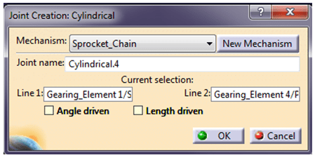
In the dialog box for Joint Creation select the 2 necessary lines(axis), let the rest untouched and click OK.

At this stage after you´re done with joints creation, Catia informs you again that the mechanism can be simulated. Click OK one more time and you are all set. You can now run the simulation for your mechanism.
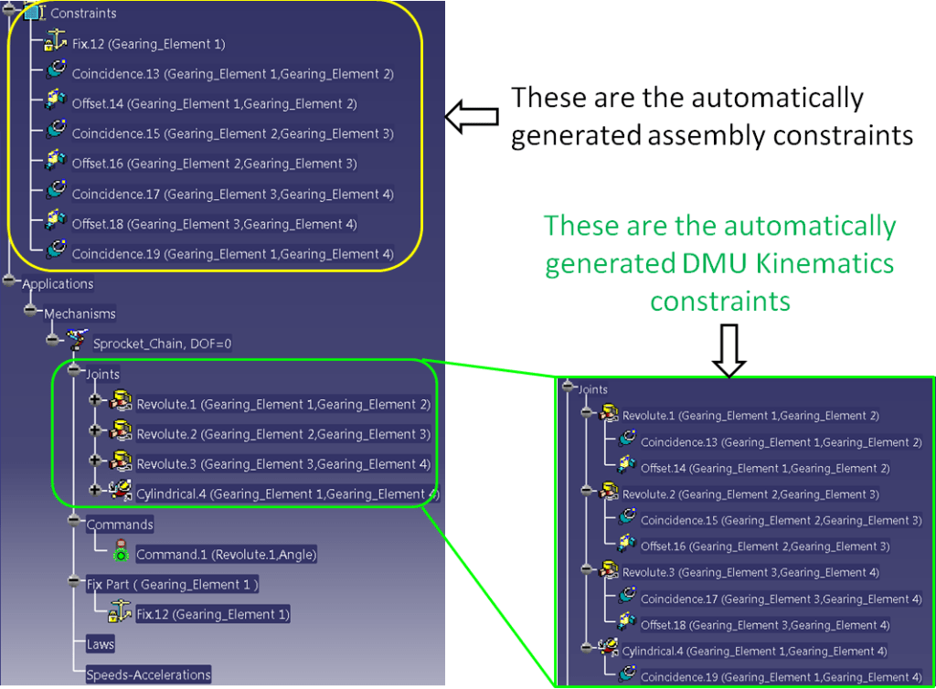
In the specification tree all the joints and related constraint will be automatically displayed. By double-clicking on any of them you can edit their values and update your mechanism anytime. Your SpecificationTree will look like this:
Simulation with commands
Step 1.
Once you have the mechanism fully defined, you can have a first overview with a quick simulation using the mode “Simulation with commands”

In the DMU Kinematics toolbar click on the icon “Simulation with commands”
In the dialog box if necessary click on the More>> button to expand the dialog box and see all the available settings. Very important to notice that in case you work with multiple mechanisms in the same assembly you must be careful and always select the proper Mechanism before you proceed with any other settings. Make sure you have the right one selecting it by clicking the little black arrow pointing downwards on the far right of the Mechanism Name. In this exercise we only have 1, Mechanism : Sprocket_Chain. So in this case no need to worry. You can simulate easily.

IMPORTANT : Keep this dialog box open all the time when you perform a “Simulation with Commands”.
Step 2.

Choose which type of simulation you wish to perform: “immediate” or “on request”
Step 3.
If you choose “immediate” option” you can directly simulate by changing the command value.

Because our defined driven command is “Angle Driven” the displayed values are in the range from -360° to 360°. You can play with values in this range by changing the command initial value. The command value can be changed in 3 ways:
- By moving the slider in the command line, to the left or to the right (you must click on it and you can either move it with the mouse- hold the left click and drag it or just click on it and move it with left & right arrows on your keyboard)
- By manually changing the value
- By clicking the little up & down black arrows next to the initial value
Additionally you can set the Slider lowest, highest and spin box increments by clicking the far right 3dots button.
Step 4
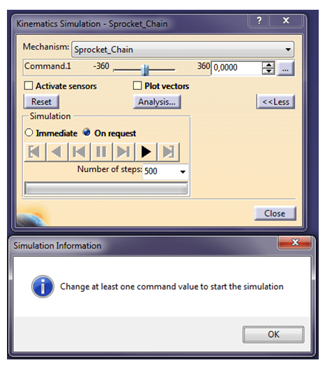
For simulation “on request” you MUST first change the command value. Initially the slider is positioned in the middle, so just click on it and change its position or type manually another value. Otherwise simulation cannot be performed. Catia will give you a short notification to do it anyway. If that happens, just click ok and change the command value as requested.
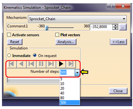
Once you change the value for “on request” simulation you will activate the video switching panel, allowing you to play with your mechanism as much as you like. Here you can also adjust the number of steps you want to see in the simulation.(for example 500) These steps will directly influence the speed of motion of your mechanism. The bigger the number of steps, the slower the motion of your simulation will be.

The video switching panel works exactly the same like on any other video player.
Just below the Command line there are 2 additional functions which for now you can let them unticked. “Activate sensors” + “Plot vectors” and Analysis button ( But I will talk about these 3 in another exercise).

After you´ve successfully done your simulation, I highly recommend you to click the Reset button before you close the Simulation with Command Mode. Like that, in case you want to redo the simulation later you can be 100% sure that your mechanism will always be in the starting position.
Exercise DONE. This is how “Simulation with commands works” in CATIA V5.
In the video below you can also watch how I did this exercise with the steps I´ve just described above. In The next one I will show you how to create a Simulation with Laws.

This is very interesting, You’re an overly skilled blogger.
I have joined your rss feed and stay up for seeking more of your wonderful post.
Also, I have shared your website in my social networks
LikeLike
I appreciate this. ;-). Thanks a lot.
LikeLike
Everytime I create a joint, a new command.x appears. How do I only limit myself to only 1 command appearing?
LikeLike