
In my previous post I showed how the Simulation with commands works in CATIA V5. For this type of simulation there is no time related function versus the command value, therefore all what you need for this is to define a driven command, create the kinematic joints and simulate the mechanism by changing the command value in the dialog box when Similaton with command icon is clicked. Once you close the dialog box you close the simulation too. If you want to see it again you must repeat the procedure and click again on the simulation with commands icon.
In this post I present you the second possibility to simulate a mechanism with Cata DMU Kinematiscs. This is:
Simulation with laws
For this one additionally to the command value used for Simulation with commands mode we can use the Time parameter to define the simulation rules. In order to create such rules we must first create a formula in which we put the command value in relation with the time parameter. It is also possible that our assembly can have multiple mechanisms or we can have multiple driven commands but for this exercise we use only one driven command which is “Angle driven”.
We will simulate with laws playing with the mechanism at different angles of motion. Let´s start.
Step 1.

Open the last CAD data we used at the previous exercise the “Sprocket_Chain.CATProduct”
Step 2.
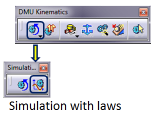
In the DMU Kinematics toolbar we will use the Simulation with laws icon, but not yet, because it won´t do anything until the rule is created.
In case you still click on this Simulation with laws icon, CATIA won´t let you simulate anyway and it will even notify you to create the formula first. Without formula all what you get is this message:

Then do as requested.

To create the relation between a command and the time parameter in the Knowledge toolbar click on the Formula Icon
In this dialog box do the workflow as follows:

In the Filter Type make sure the type Angle is selected. If it´s not, then expand the drop-down menu by clicking the little black arrow pointing downwards and in the list pick Angle. Do the same checking for the new parameter type which must be Time and then click Add Formula button (or double-click on the previously selected parameter “Sprocket_Chain\Command.1\Angle” in the parameter window)
A new dialog box will be opened which is a window in 3 columns, do the selection as shown here:

By double-clicking on the selected line in Members of Time column this will appear as the first part of formula to which we manually add /1s*360deg which will define the relation between time parameter and command value, therefore corresponding to a 360° angle per second.
In the bottom line of this dialog box the same line is shown having the editable time value at 0s (if you wish to define a different time for your simulation you can change the value here but for this exercise just keep it as it is), then click OK.
The Formula Editor dialog box will be closed and now you are back to the previous dialog box which now looks like this:

The formula has been created and displayed as Active (yes) in the Formulas dialog box. You can now change it anytime later if you wish, just open this dialog box again and double-click on the formula line, the Formula editor dialog box will be open and you can edit the formula with a new mathematical relation.
In case you don´t need a parameter of a formula anymore, you can always delete it by clicking the Delete Parameter or Delete Formula buttons. But for us we all is good here, click OK.
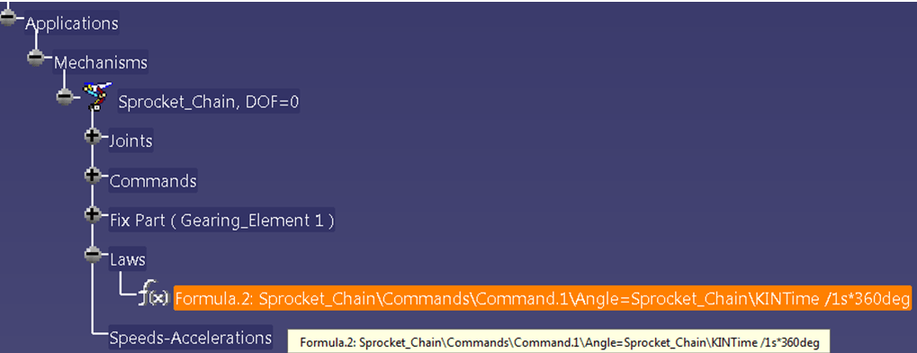
The Rule is now displayed in the SpecificationTree as feature under ApplicationTree as shown.
Now we can do the Simulation with laws.
Step 3.

In the DMU Kinematics toolbar, click on the icon Simulation with laws.
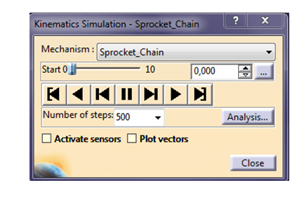
In the dialog box if you have multiple mechanisms in your assembly very important first thing to do before anything else, is to make sure you are doing the simulation for the right mechanism, therefore check in the first line the Mechanism name if that´s the one you want to simulate, if not pick the right one from the drop-down list activated by the small black arrow.
In our case we have only 1 mechanism so, we can directly continue the workflow. In my previous post about Simulation with commands in a similar dialog box we did the simulation by changing the command value. For this one the value we change is the time parameter. But the working procedure is the same. (If that´s not really clear review my previous post about DMU Kinematics)
You can change the time parameter values either by dragging the slider to the right (or left), or manually insert the wanted value or by using the little black up & down arrows next to the displayed value.
Because in this simulation mode is time related, there are no negative values, therefore the range of values starts from 0 (Zero). In our example the default time range is defined from 0 to 10 seconds.

If you are not satisfied with the 10s default time for your simulation, click the 3 dots button on right side in dialog box and change the maximum time bound with the value you need.

Depending on how fast you wish to do the simulation you can also adjust the number of steps. You can either pick one of the available numbers or you type in the number you want. The bigger the number, the slower the simulation will be.
The Video Switching panel is always on, you can play the simulation and if that runs not really as you expect, you can anytime adjust the values at your best convenience.
Again, in this dialog box the same like we have seen at Simulation with commands, there are 3 additional setting option such as “Activate sensors” and “Plot vectors” plus Analysis… button, but for now just leave then unchecked (these will be discussed in another post).
Once you´re done with the simulation I recommend you to always put the time setting back to 0 (zero). This will surely help later when you want to redo the simulation from its initial position. So set the time parameter to zero and close the Kinematic Simulation dialog box.
At this stage the only difference between the 2 simulation modes (with commands and with laws) is the formula creation for time dependence for the Simulation with laws. But once you close the dialog box the simulation is still not added as feature in the Specification tree. To add the simulation with law in the specification tree we must edit it first.
Editing the Simulation.
In the two simulation scenarios we have seen, we have changed only 1 value, either the command value in Simulation with commands which was the Angle or the Time parameter in Simulation with laws. But using the Simulation Editor we can also apply different values for a command or time parameter and therefore do a complex simulation with multiple motion sequences by putting the mechanism in different positions.
We will do a simple simulation in which our mechanism will run with multiple values of commands, one after another.
For example , the mechanism will run from the starting position to 90° angle clockwise and then back counterclockwise with 60°. Finally it will run up again with 60°clockwise and back to initial position to zero 0°.
Let´s see how it works.
With this function we have the possibility to initiate and demonstrate a simulation for a mechanism in different positions and we can generate a complex motion sequence. The chosen positions and their corresponding motion can be easily played using the video switching panel.
Step 1
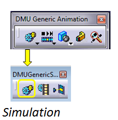
In DMU Generic Animation toolbar Click the icon Simulation

In the dialog box select the simulation object and click OK. ( If you preselect the object in the SpecificationTree before to click the Simulation Icon, this selection dialog box won´t be displayed, you will directly see the two editing dialog boxes).
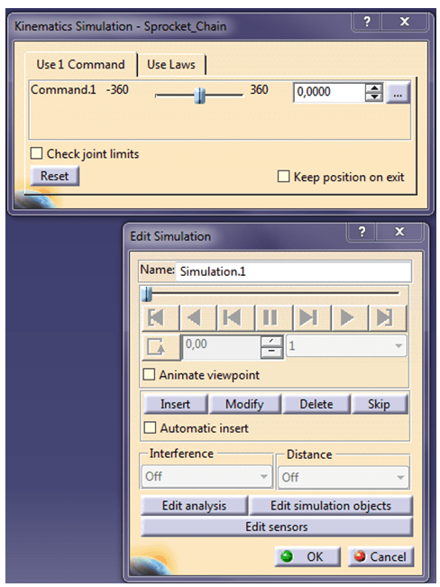
Two new dialog boxes will be simultaneously displayed as shown.
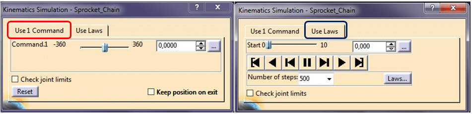
The Kinematic Simulation dialog box has 2 tabs but for this exercise you must stay on the left side Use 1 Comand tab. The one on the right side is similar with the dialog box which opens when you click on Simulation with laws icon (as I ´ve showed you earlier) with the exception of Laws… button which I will present in another post. For now leave the right side untouched, stay on the left side.
As you have already noticed at the first view the slider in the Kinematic Simulation dialog box is positioned in the middle and the Edit Simulation dialog box is inactive, so all what you can do in order to see a motion is to move the slider in the first dialog box to the left and to right but that doesn´t help you much. To preform a useful simulation you must insert at least one value. As I´ve mentioned earlier with this function we can simulate a mechanism in different positions all in one session. So let´s insert 4 values.

The values must be successively inserted, so In the Kinematic Simulation dialog box:
– type 90, press enter and click Insert in the Edit Simulation dialog box.
Repeat the procedure with: 30, 90, and 0.

When all the values are inserted, your Edit Simulation Dialog box will look like this. The interpolation step is often by default set on 1 but this is too fast. You will usually play the simulation much better with lower values so take 0,04 or even 0,01.
The video switching panel is now active and you can play the simulation with the 4 inserted positions.
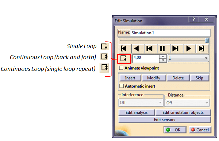
Also important and useful option is the Change Loop Mode button. With a single click on it you can chage the loop mode you wish to see your simulation.
If you wish to review the 4 positions you have inserted you can do this by clicking the up & down black arrows next to the amount of inserted values. Don´t type it manually and click enter because you will close the simulation without seeing it first.
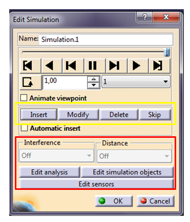
In case the inserted values must be adjusted you can easily Modify, Delete or Skip but clicking on any of this buttons.
The 2 extra options “Animated viewpoint” and “Automatic insert” are not important now so leave them unticked
The same with the 3 available buttons on the bottom, we´ll take later about these.
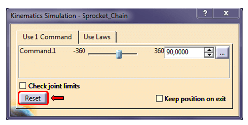
The same recommendation in this case as well, whenever you finish a simulation don´t forget to press the Reset button before you close the dialog box. Then click OK.

Your simulation is now available and added in the Specification tree as feature under Application tree, which now looks like this.
Exercise DONE. This is how “Simulation with laws” works in CATIA V5.
In the video below you can also watch how I did this exercise with the steps I´ve just described above. In the next one I will show you how to create a replay and how to compile your simulation in video file.

Good job Florin
LikeLike
Thank you very much ;-).
LikeLike