
A very frequent type of feature used in mechanical design development is the Revolved feature. There are many common working approaches with the Extruded part but as we are dealing with a different shape in this post I will show you how specifiaclly a Revolved part is created with CREO Parametric 6.0.
STEP 1:

As usual every new part starts with the definition of the working file. So click on “New” icon, select the type Part, rename your file and click ok.
Creo will put you by defaut in Model workbench. On the Shapes ribbon click on the Revolute icon.

Creo will open a new workbench where you must define the Revolve parameters. Select the options as shown and click Sketch.
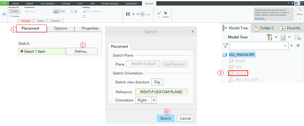

In the Sketch workbench most probably your view is not oriented parallel to the screen, so click in Sketch View in order to have it so.
STEP 2:
In the Sketch workbench all the time when you intend to create a revolved part I suggest you to start with the Centerline. You must create and define the rotating axis for your part. So click on “Centeline” icon and draw a horizontal centerline. If that must be coincident with the reference axis just click again on the line, click on the “Coincidence” icon and finally click on the reference line. Creo will make your center line coincident with the horizontal axis.

In case more Centerlines are needed to define your sketch, you can draw as many as needed but then you must define which one must be taken as “Axis of Revolution”.

To designate which centerline shoud be the Axis of Revolution, click on the line and hold right click on it. Creo will open a drop down list of commands where you have the option to Designate the main axis. Click on this option and continue your sketch.
STEP 3:
In this exercise, the is no need to have multiple centerlines, so create only one and make it coincident as expalined above. Then click on “Line” icon and draw the profile as shown.

By default Creo will create your profile with weak dimension, meaning the sketch completelly free of constraints. It can move anywhere on the screen. To have a fully defined one you must define the dimensions. So modify your sketch entering the dimensions as shown below.

Even is you modified the values your sketch is only temporary defined. Meaninng that it shows you how the part profile looks like but if you click and drag a point or a line in your sketch the dimension will move accordinly. So to be sure nothing moves, left click on each dimension and use the “Toggle Lock” icon in order to lock the dimension and prevent any accidental change.
STEP 4:

Once the sketch is fully constrained, in order to avoid surprises , it is always good to inspect your work by clicking the “Feature Requrements” icon. Creo will tell you if everything is alright oor not. (This is very useful command mainlw for beginners – but in many cases vey helpful for advanced designers).
STEP 5:
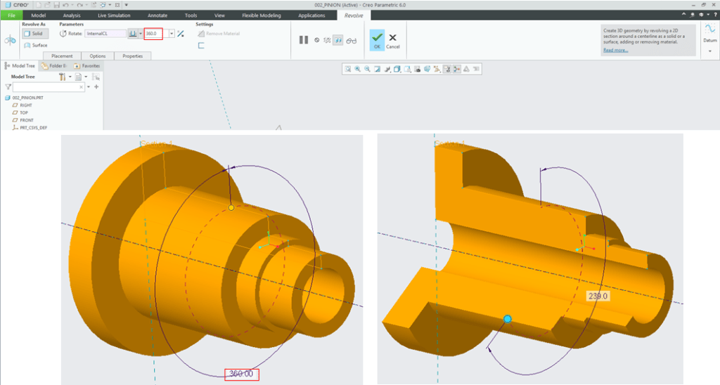
After the sketch definition, Creo will put you back in Revolve workbench where among few other parameters you must define how your part must revolve. In this case it’s a full shaft, therefore keep the 360° rotation angle, and click OK.
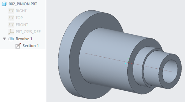
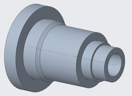
This is the resulted Revolved part.
STEP 6 (additional; just for practice):

In case you want to add new lines in the sketch definition, as the Revolve feature is added in the Specification Tree, do a left click in Section1 under Revolve1 feature and choose Edit Definition icon.
STEP 7(related to step 6):
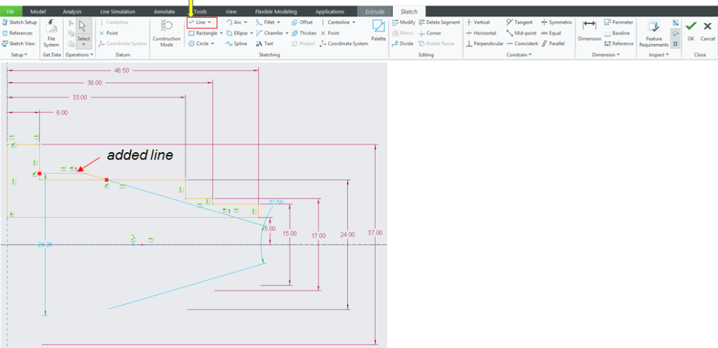
Creo will put you back in the sketch workbench. Here click on the Line icon and add 2 new lines as shown.
STEP 8 (related to step 6) :
As you see by the addition of the 2 new lines, Creo doesn’t know anymore how to generate a full profile, therefore 2 red points are highlighted on the sketch wireframe, meaning the you must clean it up before to exit the Sketch workbanch. For this click on the Delete Segments icon and trim the extra lines as shown.

STEP 9 (related to step 6) :
Now as the sketch is clean again, Creo can generate the Revolved part. Before to exit, click the “Dimension” icon and modify the new dimensions as shown.

It can happen that during the sketch definiton some constraints are added by default, and when you want to define a new one, Creo will notify you that the sketch is overconstrained. Therefore you either transform some solid constrains as reference only or you completelly delete the unnecessry one.


When everything is clear with all the dimension, do a final inspection one more time and if all is good , click close and click OK to exit the sketcher workbench.
This is your final revolute part.
You can also follow this exercise on my YouTube Channel as follows:

Leave a comment