Blog Feed

CREO PARAMETRIC 6.0 – Audi Wheel Rim Design

A wheel rim design can be done in different ways, depending on the wanted pattern and the used CAD software. In this example I show you a version of Wheel Rim used on AUDI cars and how to do it in CREO Parametric CAD software. A wheel rim can also be done in 1 piece... Continue Reading →

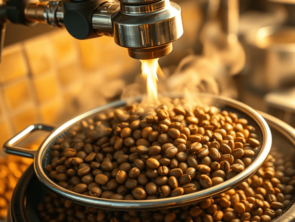
The Art of Coffee – How to make a good coffee?

After, Water and Tea, the 3rd one most consumed refreshment drink must be the COFFEE. At some point I am tempted to put coffee in the same position with tea as both being the 2nd most consumed drinks on the planet, but I guess Tea better deserves the 2nd place. Like Tea, making a good... Continue Reading →

THE ART OF TEA – How to make a good Tea?

I am sure most people will say, what's so much of science to make a good tea? Should not be a big deal, simply take a bag of tea or tea leafs and put it in a cup with boiled water, then add some sweetener and done. The tea is ready. Right? Well... things are... Continue Reading →

SOLIDWORKS – Bug Rover _ Part 4 – Assembly Design

As we've already seen in the previous posts, The Bug Rover is made of various components. In this post we'll put everything together in the final product. But before to create the final assembly, let's create first the Sub-Assembly called Carterpilar which will be later used as multiple instances for the final assembly. Let's start:... Continue Reading →

SOLIDWORKS – Bug Rover _ Part 3 – Carterpilar Design

In this Part of Bug Rover design work, I'll show you the 3 main components of the Carterpilar assembly. These are: The Star Gear, The Gear Cap, The Wheel and The Carterpillar. Let's start: THE STAR GEAR STEP 1 Create a new part STEP 2 On Front plane draw the following sketch and revolve it... Continue Reading →

SOLIDWORKS – Bug Rover _ Part 2 – Lever Design

In this 2nd part of design work for the Bug Rover, I'll show you the next 2 main components: The Lever and The Lever Cap. Let's start: THE LEVER STEP 1 Create new part STEP 2 Create the following 2 sketches: STEP 3 Use the previous 2 sketches to create a Project Curve STEP 4... Continue Reading →

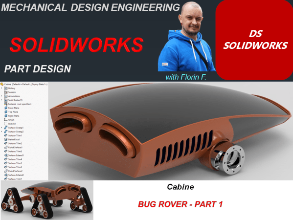
SOLIDWORKS – Bug Rover _ Part 1 – Cabine Design

A rover design work implies a lot of details and components. In this article I want to present you a simplified version of a reover concept I did, which is inspired from the insects world. It really looks like a bug, so I name it Bug Rover. I will only put here the main bodies... Continue Reading →

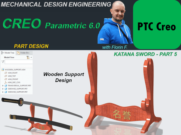
CREO PARAMETRIC 6.0 – KATANA SWORD DESIGN_Part 5 – Wooden Support Design + The Final KATANA SWORD Product.

A Katana Sword is not just a regular object. It is a symbol of honor and respect, it's almost like a medal. Therefore it must have a specific way of storing. The most common is a wooden support which serves either for the sword inside the scabbard or both the sword and scabbard seperatelly. In... Continue Reading →

CREO PARAMETRIC 6.0 – KATANA SWORD DESIGN_Part 4 – Scabbard Design

When a samurai doesn't use his sword he let it in scabbard. The work design for this element goes as follows: STEP 1. Create new part in Assembly workbench as shown: STEP 2. In Model workbench, click on Sweep icon and then create the trajectory in a sketch on DTM3. Just project the upper top... Continue Reading →

CREO PARAMETRIC 6.0 – KATANA SWORD DESIGN_Part 3 – Handle Design

Let's continue with Katana Sword design. Handle design is done as follows: TSUKA - HANDLE STEP 1. The design work must continue in the same Top-down approach, like we did in Part 2. This means that the new parts are created directly in the Ansembly file using the original reference system form Blade part. Therefore... Continue Reading →

Website Built with WordPress.com.

Up ↑