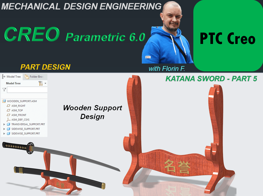
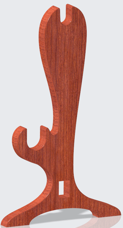
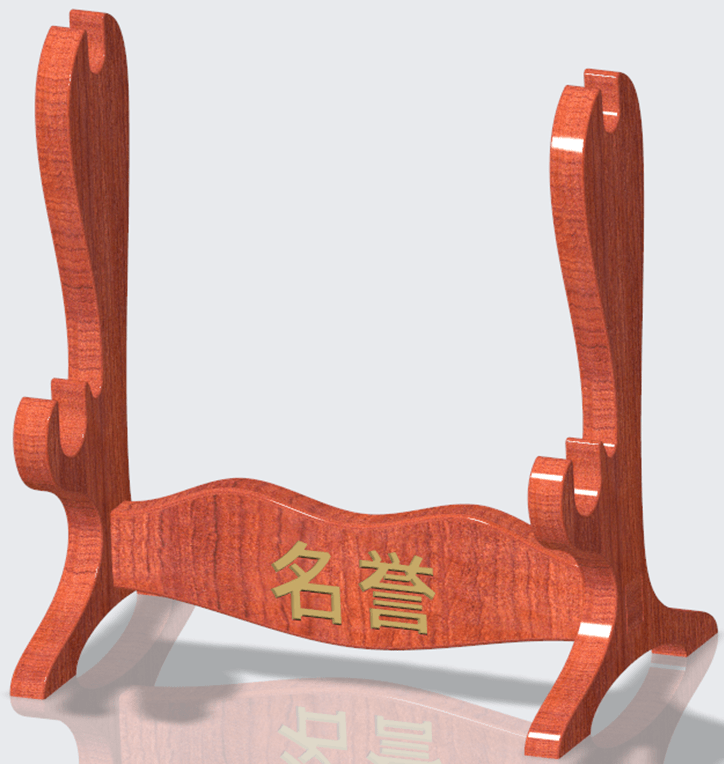
A Katana Sword is not just a regular object. It is a symbol of honor and respect, it’s almost like a medal. Therefore it must have a specific way of storing. The most common is a wooden support which serves either for the sword inside the scabbard or both the sword and scabbard seperatelly. In this part I’ll show you how I did the wooden support with CREO Parametric. The work goes as follows:
The wooden support is actually made of 2 different sub-elements. 1 Transversal part and 2 Sidewise Supports.
TRANSVERSAL SUPPORT.
STEP 1.
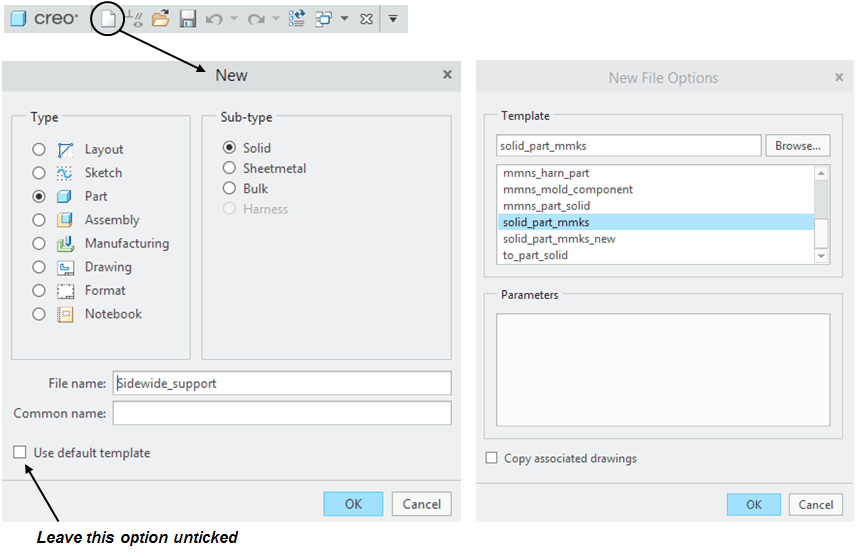
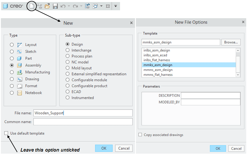
Create New part
STEP 2.
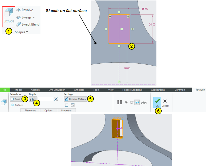
Click on Extrude icon and on Right Plane Sketch the following profile, then extrud it 15mm by mid-plane:
STEP 3.
Now to insert the japanese script engraving the best way to do it is to convert a image file (such as png format) into dxf file. From the variety of conversion sofwares available, I highly recommend you to use Inkscape. Just go to the download page, download the exe file and install it on your PC.
then, using Inkscape convert the following script from png file to dxf file.
STEP 4.
Once the dxf is available, sometimes you can use it directly in CREO sketches but in this case I suggest you to create an additional sketch file where you make the clean version before to use it in CREO part file. This is becasue, the conversion creates a raw sketch made of lines and a lot of inflexion points which won’t really give you the result you expect on the 3d Part.
Therefore insert the dxf into a new sketch file and based on the conversion result remove all the inflexion point and redraw the script using only arcs and lines as shown:
… then save the sketch file as it is.
STEP 5.
Click on Extrud icon and select the flat surface a reference for sketch plane. In sketch workbench click on File System icon (n°3) and open the previosly saved Sketch file. Then adjust the position + scale and remove 2mm of material as show:
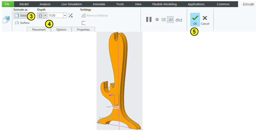
STEP 6.
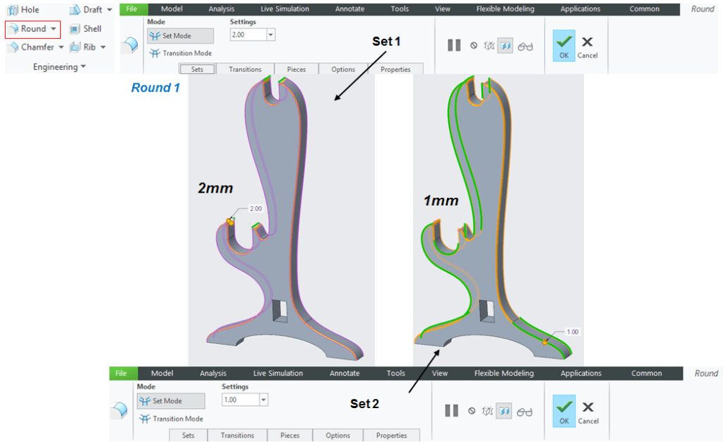
Add rounds as shown:
STEP 7.
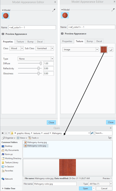
Add appearances
SIDEWISE SUPPORT.
STEP 1.
Create a new part.
STEP 2.
Click on Exrude icon and on Front Plane draw the following sketch:
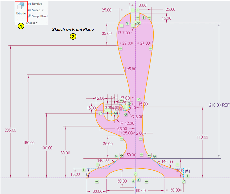
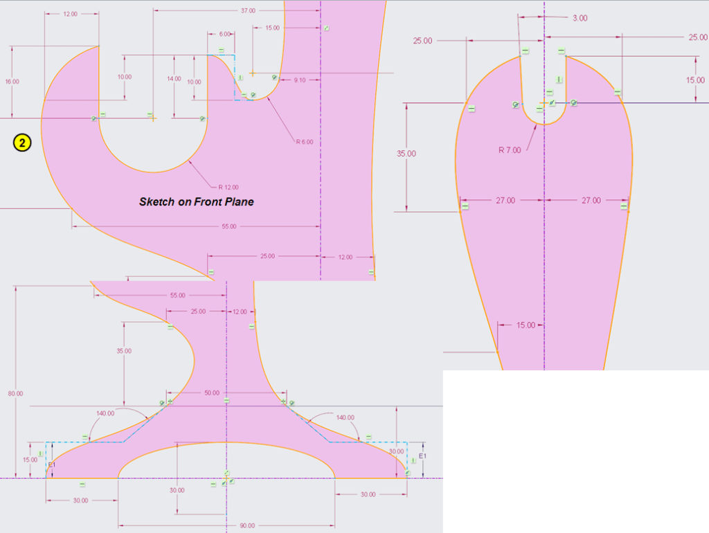
… then extrude it 15mm by mid-plane.
STEP 3.
Click again on Extrude icon and on the flat suface sketch a rectangle as shown:
STEP 4.
Add one round feature in 2 sets as shown:
STEP 5.
Add appearance:
The part design is finished.
WOODEN SUPPORT ASSEMBLY
STEP 1.
Create a new Assembly
STEP 2.
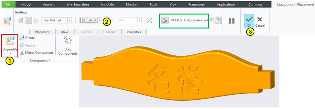
In Assembly workbench, click on Assembly icon and make the Transversal support the default part.
STEP 3.
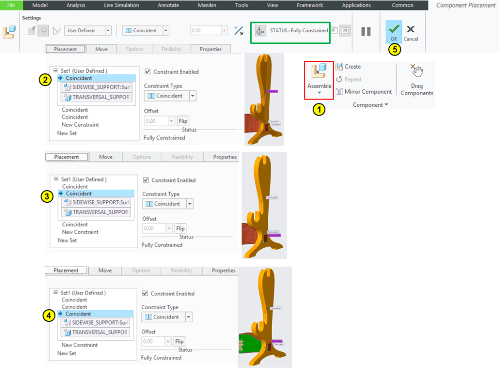
Add the 2 Sidewise supports:
KATANA SWORD – THE FINAL PRODUCT.
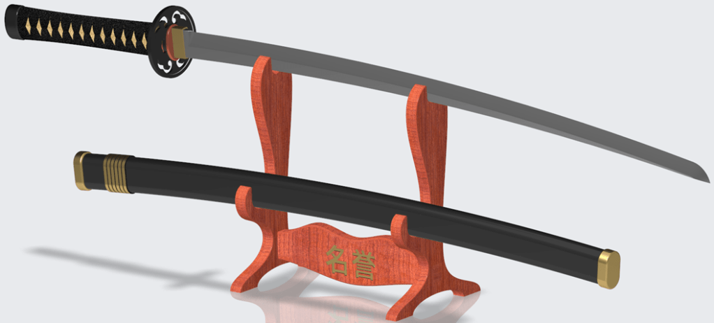

This design work is also available as video version on my YouTube channel as embedded below:

Leave a comment