MECHANICAL DESIGN ENGINEERING – GD + T – General terms about geometric characteristics and their attributes.

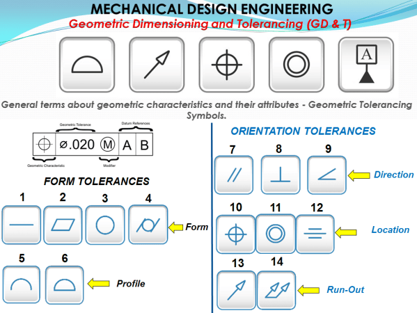
Geometric Dimensioning And Tolerancing defines a functionality of a part and because the part drawing is the first tool people use in order to manufacture a part, the designer must clearly specify all the necessary characteristics which will communicate further how that part must be produced and how it will finally work. The part drawing... Continue Reading →

CATIA V5 DMU Kinematics_Show a simulation in different static sequences on the drawing.

In this post I will show you how can you present different simulation stages of a mechanism in few static sequences drawing. Obviously before to create a drawing you must have your 3D available. So let's create the mechanism first. For this exercise we'll do a simulation with basic design of a Hold Down Press.... Continue Reading →

CATIA V5 DMU Kinematics_Basic Mechanism – Compile simulation for Replay and export your file as video format.

After we have seen how a simulation can be done with CATIA DMU Kinematics; let's see how to replay it anytime we want to see it again. Or we can even generate multiple replays in case we want to see multiple simulations with the same mechanism. Additionally it is also possible to compile a simulation... Continue Reading →

MECHANICAL DESIGN ENGINEERING – When do we use GD + T and How does it work?

The term "Product Design" covers a large area of possibilities for different applications. We have Product Design in Mechanical Engineering but this is also done in Software Engineering (i.e App development, WebSites, AI applications, etc), Electrical Engineering (i.e. PCB design, Semiconductors, Superconductors,), Nanotechnology, etc, all these have their own Product Design guidelines and norms. But... Continue Reading →

MECHANICAL DESIGN ENGINEERING – Why you MUST apply Geometrical Dimensioning and Tolerancing on your Product Design?

In product development environment there is nowadays a commonly and often mentioned acronym as CAD which stands for: Computer Aided Design. That is to say that the convetional way how mechanical engineering was done in the past can now be done with assisted by a computer programm. And that is excelent. It clearly speeds up... Continue Reading →

CATIA V5 _DMU KINEMATICS_Basics Simulation with Laws

In my previous post I showed how the Simulation with commands works in CATIA V5. For this type of simulation there is no time related function versus the command value, therefore all what you need for this is to define a driven command, create the kinematic joints and simulate the mechanism by changing the command... Continue Reading →

CATIA V5 _DMU KINEMATICS_Basics Simulation with Commands

In order to generate a simulable mechanism in Catia V5 you need to define 3 basic things: Define a fixed part.Define a gear which will be driven by a command.Define the kinematic joints between the elements of your assembly. It can be the case, that in an assembly you might need to simulate more than... Continue Reading →

Website Built with WordPress.com.

Up ↑