Geometric Dimensioning And Tolerancing defines a functionality of a part and because the part drawing is the first tool people use in order to manufacture a part, the designer must clearly specify all the necessary characteristics which will communicate further how that part must be produced and how it will finally work. The part drawing is the birth certificate of a part, everyone involved in its development & production process must have a good understanding how this will happen and therefore creating and reading the part drawing is essential in order to understand all the details. For this reason GD & T is the international communication language in product development. It helps to read drawings for engineers, designers, manufacturers etc. what surface has to be machined carefully.
The benefits of using GD& T have a huge impact on the quality, functionality and lifetime of a part. These benefits are:
- Geometric Tolerancing reading helps to understand, to specify and control the form, location and orientation of the features of components and manufactured parts.
- Geometric Dimensioning and Tolerancing is an efficient method for describing the tolerancing mandated by the designer of the part. The Datum axis or Datum planes are to be used for locating other features.
- With GD&T all inspection will result in the same result. It will help to understand if the dimension is within or out of tolerance.
- Geometric Dimensioning and Tolerancing forces the designers to totally consider functions, manufacturing processes, and inspection methods.
These explanations would be good answers to why GD&T should be used. The chosen geometric tolerance and modifier/modifiers will be shown in Tolerance Feature Indication/Feature Control Frame.
There are several standards available worldwide to describe the symbols and the rules. These are:
The American Society of Mechanical Engineers, ASME Y14.5M-2009, (GD&T – Geometric Dimensioning and Tolerancing) and
International Organization for Standardization, ISO/TC 213, (GPS – Geometrical Product Specification) and ISO/TC 10 Technical Product Documentation.
Dimensional tolerances are most important specifications for the practice of engineering drawings. However, there are also products for whose function and cost-effectiveness of manufacture it is essential to enter additional form and position tolerances. The term “form and position tolerance” is used as a generic term for the geometric features of form, direction, location (i.e. position) and runout. In the GPS (Geometrical Product Specification) standard DIN EN ISO 1101, the principles of symbolic representation and entry on drawings as well as the establishment of geometric definitions are given.
For a further understanding of form tolerancing, it is helpful and important to consider simple basic geometric bodies. Therefore, a product is made up of individual parts: lines, planes, circles, cylinders, spheres and cones. The GPS standard ISO 14660 provides the basic terms and definitions for geometric elements.
An element or geometry element is: a point, a line or a surface.
A complete geometry element is a surface or a line on a surface.
A derived geometry element is a center point, a middle line, or a middle surface that is derived from one or more complete geometry elements.
A geometric form that is defined by a length or angle is called a dimensioning element. In connection with the term dimension tolerance, the term nominal dimension was defined. The term “nominal geometry element” is defined accordingly.
A nominal complete geometry element is a theoretically accurate, complete geometry element defined by an engineering drawing or other means.
A derived nominal geometry element is a center point, a middle line or a middle surface which is derived from one or more theoretically accurate complete geometry elements. In addition, it is noted in ISO 14660 that derived nominal geometric elements on the technical drawings are generally represented by dash-dotted lines.
In the GPS standard DIN EN ISO 1101, the definitions of the tolerance terms are given as follows: “A form and position tolerance of an element defines the zone within which all elements of a geometric element (point, line, surface, center line) must lie.This zone is called the tolerance zone. The tolerated element can assume any form and any direction within the tolerance zone, unless a restrictive specification is made, e.g. as a specification with notes (words).
An nominal element is approximated by measuring it in individual points. Using mathematical methods, a geometric form that optimally passes through the measured individual points is calculated. For example a line, a plane or a cylinder jacket. In this context, optimal means that a previously agreed dimension for the perpendicular distances between the individual points and the calculated geometric form is minimal. If the perpendicular distances between the individual points in front of the calculated geometric form (line or surface) are equal to or smaller than the specified tolerance, then the manufactured part is assumed to be flawless.
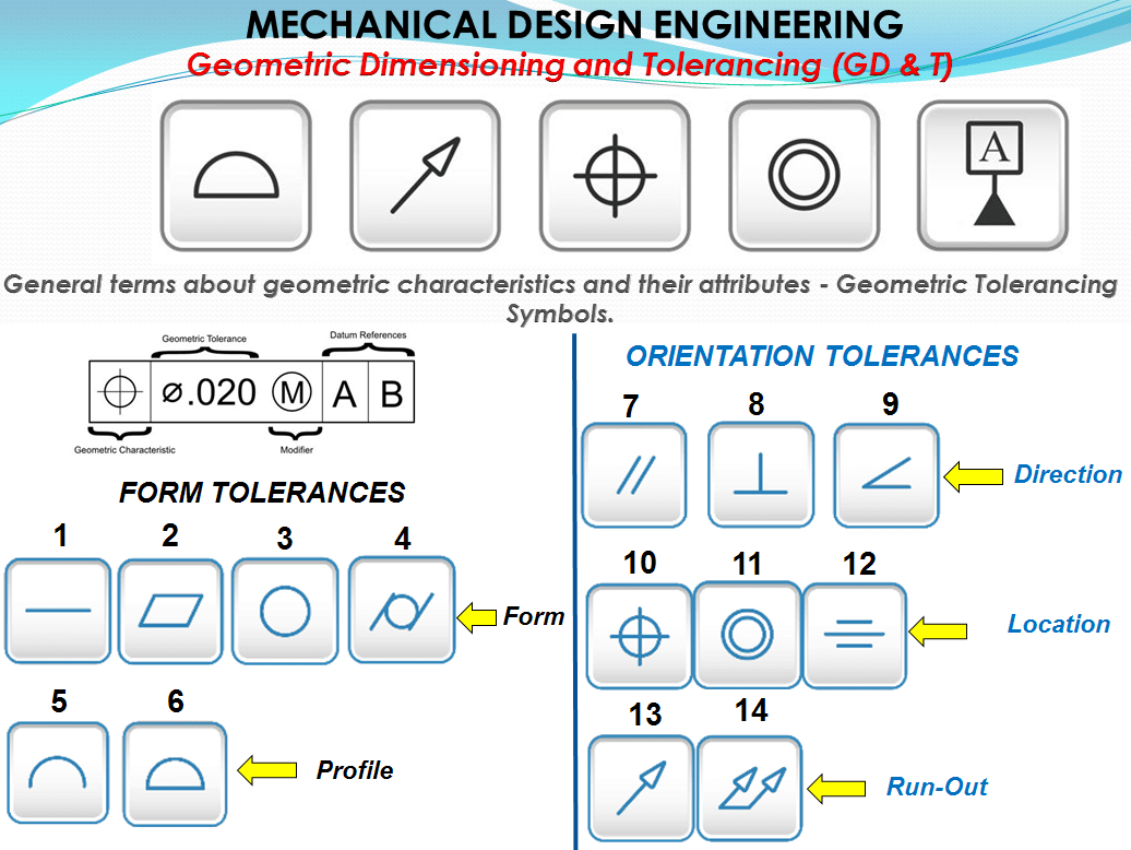
Geometric Tolerance Groups.
DIN EN ISO 1101 contains 14 tolerances which are divided into 2 large groups. These are:
Form tolerances which relate to a single geometric element
Orientation tolerances in which at least 2 geometry elements are involved
Therefore, the position and orientation of the tolerated element generally relates to the reference element; these are also referred to as related tolerances. Profile tolerances can, however, appear either as pure form tolerances or with reference elements, i.e. as position tolerances.
Tolerance zones.
The tolerance zones of the different types of tolerance, generally have the ideal form of the tolerated geometry element.The latter must be completely within the tolerance zone. In terms of their form, two different types of tolerance zones dominate:
Straight-line tolerance zones = are limited either by 2 planes (in the limiting case, 2 straight lines) or by a circular cylinder (small tube). They occur with “flat” form tolerances, with directional and location tolerances. Tolerated geometry elements are therefore straight lines (real straight lines and axes) and planes (also real and central planes).
Ring-shaped tolerance zones = lie between concentric circles, coaxial circular cylinders, etc. They occur with “round” form tolerances and runout tolerances, and in practice only with real geometric elements with (at least partially) circular cross-sections.
Therefore, there are close relationships between the above-mentioned tolerance groups. For now I am just introducing the concepts of reading these tolerances and later I will talk more specific about each of these 14 tolerance characteristics.
Reference datum planes.
As a reference for a tolerated element, the geometric element should be chosen as much as possible as the one, which also serves as starting point for the function of the workpiece. Hence we can have: Primary Datum, Secondary Datum, and Tertiary Datum Planes: These Datum Planes must be perpendicular to each other.
Primary Datum Plane: The primary datum is selected to provide functional relationships, standardization and repeatability between surfaces. A standardization of size is desired in the manufacturing of a part. Consideration of how parts are orientated to each other is very important. The chosen primary datum must insure precise measurements.
Secondary Datum Plane: Secondary datums are produced perpendicular to the primary datum so measurements can be referenced from them.
Tertiary Datum Plane: Tertiary datum is always perpendicular to both the primary and secondary datums ensuring a fixed position from three related parts.
These planes are illustrated as follows:

The Feature Control Frame/Tolerance framework.
Tolerance control frame is a rectangular symbol which contain indications which define the geometrical tolerance for features. Geometric Tolerance defines the form and the size of a tolerance zone.
The tolerance zone may be one of the followings:
- the area within circle,
- the space between 2 coaxial cylinders,
- the area between 2 parallel lines,
- the space within a cylinder,
- the space between 2 parallel surfaces or 2 parallel planes,
- the space within a geometrically square or rectangular prism or a solid with 6 faces,
- the area between 2 concentric circles
The geometric tolerances are indicated in a rectangular frame, which is divided into 2 / more boxes. These boxes contain, from left to right:
- The symbol for the property to be tolerated.
- The tolerance value in the unit of the length dimensions, diameter Ø or spherical diameter SØ
- Letters for reference elements and additional modifiers if necessary
As Fig.2 shows, the feature control frame is divided into compartments expressing the following, sequentially from left to right:
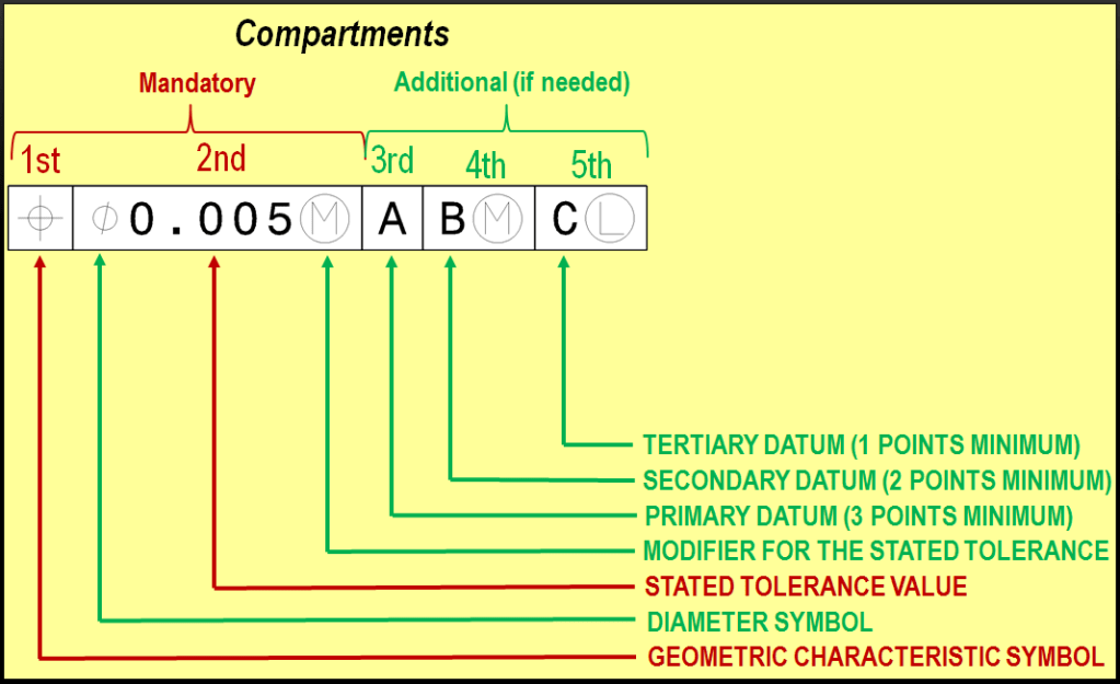
The 1st compartment contains a geometric characteristic symbol specifying the type of geometric control.
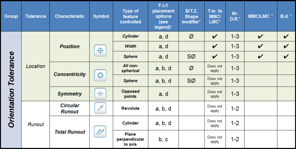
These are the 14 symbols as shown in the Table 1 (ref. ASME Y14.5M and ISO/TC 213)

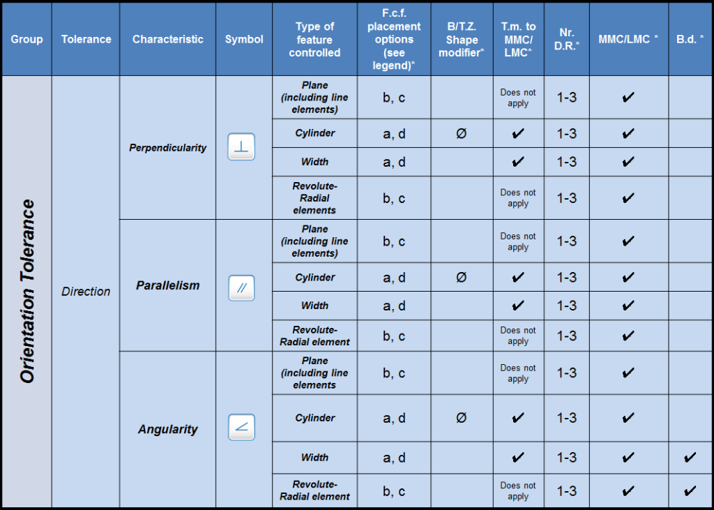
Legend:
- F.c.f. placement options = Feature control frame placement options
- B/T.Z. Shape modifier = Boundary/Tol.zone Shape modifier
- T.m. to MML/LMC = Tolerance modifiable to MMC or LMC
- Nr. D.R. = Number of datum references allowed
- MMC/LMC = material allowed for datum reference(s)
- B.d. = Basic dimensions requested
- a = place the frame below or attached to a leader-directed callout or dimension pertaining to the feature.
- b = run a leader from the frame to the feature.
- c = attach either side or either end of the frame to an extension line from the feature, provided it is a plane surface.
- d = attach either side or either end of the frame to an extension of the dimension line pertaining to a feature of size.
Table 1 summarizes the application options and rules for each of the 14 types of geometric tolerances. For each type of tolerance applied to each type of feature, the table lists the allowable “feature control frame placement options.” Multiple options, such as “a” and “d” appearing in the same box yield identical results. Notice, however, that for some tolerances, the type of control depends on the feature control frame placement. For a straightness tolerance applied to a cylindrical feature, for instance, placement “b” controls surface elements, while placements “a” or “d” control the derived median line.
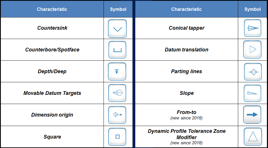
The 2nd compartment contains the geometric tolerance value. Many of the modifying symbols in Table 2 can appear in this compartment with the tolerance value, adding special attributes to the geometric control. These additional symbols also can be used on different features on the drawing not only in the Feature Control Frame.
These symbols are presented as follows (ref. ASME Y14.5M And ISO/TC 213):
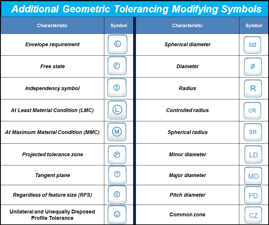

For instance, where the tolerance boundary or zone is cylindrical, the tolerance value is preceded by the “diameter” symbol Ø. Preceding the tolerance value with the “S˘” symbol denotes a spherical boundary or zone. Other optional modifying symbols, such as the “statistical tolerance” symbol, may follow the tolerance value.
The 3rd, 4th, and 5th compartments are each added only as needed to contain (sequentially) the primary, secondary, and tertiary datum references, each of which may be followed by a material condition modifier symbol as appropriate. Thus, each feature control frame displays most of the information necessary to control a single geometric characteristic of the subject feature. Only basic dimensions (which I will present in another post) are left out of the feature control frame.
Reading a Feature Control Frame
After learning the terms as mentioned above, it’s easy to translate a feature control frame into English (or any other language you speak) and read it aloud from left to right. Tables 1 and 2 show equivalent English words to the left of each symbol. Then, we just add the following English language preface for each compartment:
1st compartment—“The…”
2nd compartment—“…of this feature shall be within…”
3rd compartment—“…to primary datum…”
4th compartment—“…and to secondary datum…”
5th compartment—“…and to tertiary datum…”
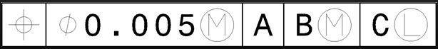
Now, read along with me Fig. 3’s feature control frame. It goes like this: “The position of this feature shall be within diameter 0.005 at Maximum Material Condition to primary datum A and to secondary datum B at maximum material condition and to tertiary datum C at maximum material condition.” No big deal, it´s easy.
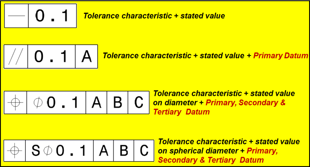
The most frequent examples are of course the simplest ones such as these shown below:
Tolerances that apply to more than one element must be entered with the number and “x”.
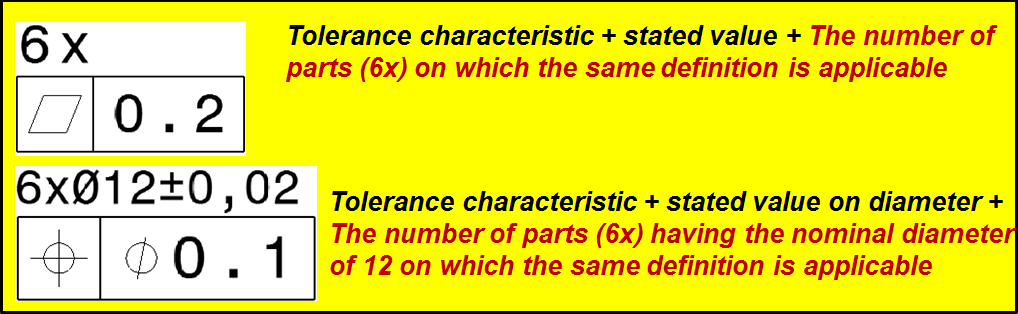
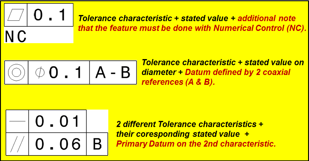
Information to describe further features within the tolerance frame must be entered near the tolerance frame. If several tolerated features are specified for an element, the tolerance specifications may be placed below one another as shown in these examples below:

Leave a comment