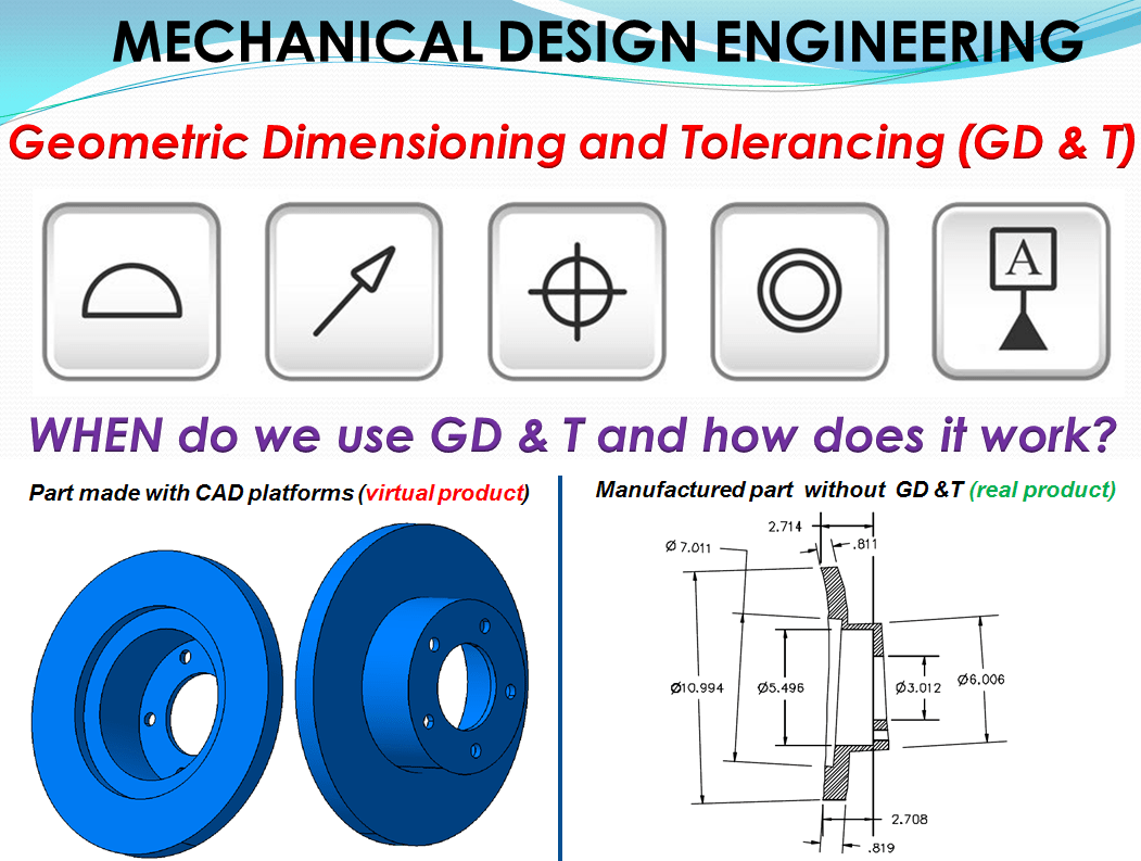
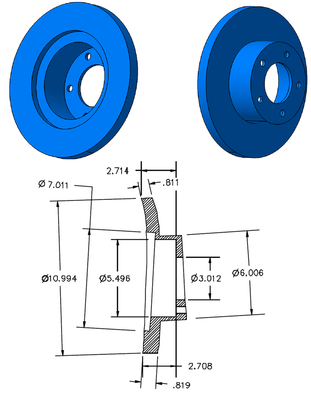
The term “Product Design” covers a large area of possibilities for different applications. We have Product Design in Mechanical Engineering but this is also done in Software Engineering (i.e App development, WebSites, AI applications, etc), Electrical Engineering (i.e. PCB design, Semiconductors, Superconductors,), Nanotechnology, etc, all these have their own Product Design guidelines and norms. But regardless of which type of product you create, you never achieve absolute accuracy. In Mechanical Engineeing the designe characteristics are communicated is a standardized laguage of graphical symbols and text known as Geometric Dimensioneing and Tolerancing (G.D.& T). With this you communicate the acceptable ranges of dimensions and geometries for your product to fullfil its purpose.
However tolerance ranges apply in the other engineering disciplines too. For instance in Electrical Engineering, Electrical tolerances are used to specify the allowable variation in the value of an electrical component. This information is crucial for ensuring the proper functioning of electronic devices, as components with values outside the specified tolerance range may cause the device to malfunction. Electrical tolerances are typically specified as a percentage of the nominal value of the component. For example, a resistor of 100 Ohms with a tolerance of 5% can have a value that is 5% higher or lower than the nominal value. This means that any resistor with a value in the range 95–105 Ω is acceptable. For critical components, one might specify that the actual resistance must remain within tolerance within a specified temperature range, over a specified lifetime, and so on.
Hence we can confidently say that GD & T is specifically a Mechanical Engineering thing. But let’s be clear on this, the GD&T It is not a creative design tool instead is a language for communicating engineering design specifications. For sure every type of product must follow specific guidelines and norms, but GD &T is not the standard for everything. Even in mechanical engineering Product Design doesn´t always follow the GD & T rules. So it´s very important to understand: WHEN DO WE USE GD &T? and how does it work?.
In the absence of GD&T specifications, a part’s ability to satisfy design requirements depends largely on the following 4 “laws.”
- Pride in workmanship. Every industry has unwritten customary standards of product quality, and most workers strive to achieve them. But these standards are mainly minimal requirements, usually pertaining to cosmetic attributes. Further, workmanship customs of precision aerospace machinists are probably not shared by ironworkers.
- Common sense. Experienced manufacturers develop a fairly reliable sense for what a part is supposed to do. Even without adequate specifications, a manufacturer will try to make a bore very straight and smooth, for example, if he suspects it’s for a hydraulic cylinder.
- Probability. Sales literature for modern machining centers often specifies repeatability within 2 microns (.00008″). Thus, the running gag in precision manufacturing is that part dimensions should never vary more than that. While the performance of a process can usually be predicted statistically, there are always “special causes” that introduce surprise variations. Further, there’s no way to predict what processes might be used, how many, and in what sequence to manufacture a part.
- Title block, workmanship, or contractual (“boiler plate”) standards. Sometimes these provide clarification, but often, they’re World War II vintage and inadequate for modern high-precision designs. An example is the common title block note, “All diameters to be concentric within 0,02mm”
Dependence on these four “laws” carries obvious risks. Where a designer deems the risks too high, specifications should be rigorously spelled out with GD&T.
The 3 main question I´ve frequently heard, and in my early engineering years I asked myself the same. The answers can be relative but at least gives a glimpse of clarity related to GT & T. So here are the topics:
Q: Should I use GD&T on every drawing?
A: Some very simple parts, such as a straight dowel, flat washer, or hex nut may not need GD&T. For such simple parts, Rule #1 (Overall Feature Form – For features of size that must achieve a clearance fit in assembly, the designer calculates the size tolerances based on the assumption that each feature, internal and external, is straight.) which pertains to size limits, may provide adequate control by itself. However, some practitioners always use GD&T positional tolerancing for holes and width-type features (slots and tabs). It depends primarily on how much risk there is of a part being made, such as that shown in Fig. 1, which conforms to all the non-GD&T tolerances but is nevertheless unusable.
Q: Can I use GD&T for just one or two selected surfaces on a drawing, or is it “all or nothing?”
A: On any single drawing you can mix and match all the dimensioning and tolerancing methods in Y14.5. or DIN EN ISO 1101. For example, one pattern of holes may be controlled with composite positional tolerance while other patterns may be shown using coordinate dimensions with plus and minus tolerances. Again, it depends on the level of control needed. But, if you choose GD&T for any individual feature or pattern of features, you must give that feature the full treatment. For example, you shouldn’t dimension a hole with positional tolerance in the X-axis, and plus and minus tolerance in the Y-axis. Be consistent. Also, it’s a good idea to control the form and orientational relationships of surfaces you’re using as datum features.
Q: Could GD&T be used on the drawings for a house?
A: Hmmm. It depends, which do you need, shanty or chateau? 🙂
How Does GD&T Work?—Overview
The goal of GD&T is: to guide all parties toward reckoning part dimensions the same, including the origin, direction, and destination for each measurement. GD&T achieves this goal through 4 simple and obvious steps.
- Identify part surfaces to serve as origins and provide specific rules explaining how these surfaces establish the starting point and direction for measurements.
- Convey the nominal (ideal) distances and orientations from origins to other surfaces.
- Establish boundaries and/or tolerance zones for specific attributes of each surface along with specific rules for conformance.
- Allow dynamic interaction between tolerances (simulating actual assembly possibilities) where appropriate to maximize tolerances.
Part Features
Up to this point, we’ve used the terms surface and feature loosely and almost interchangeably. To speak GD&T, however, we must begin to use the vocabulary as Y14.5 (or ISO 1101) does. Feature is the general term applied to a physical portion of a part, such as a surface, pin, tab, hole, or slot. Usually, a part feature is a single surface (or a pair of opposed parallel plane surfaces) having uniform shape. You can establish datums from, and apply GD&T controls to features only. The definition implies that no feature exists until a part is actually produced. There are two general types of features: those that have a built-in dimension of “size,” and those that don’t.
Q: Is a center line a feature?
A: No, since a center line or center plane can never be a physical portion of a part.
Q: Well, what about a nick or a burr? They’re “physical portions of a part,” right?
A: True, but Y14.5 doesn’t mean to include nicks and burrs as features. That’s why we’ve added “having uniform shape” to our own description.
Q: With transitions at tangent radii or slight angles, how can I tell exactly where one feature ends and the adjacent feature begins?
A: You can’t. The Math Standard (ASME Y14.5.1M-1994) points out, “Generally, features are well defined only in drawings and computer models.” Therefore, you are free to reckon the border between features at any single location that satisfies all pertinent tolerances.
Nonsize Features
A nonsize feature is a surface having no unique or intrinsic size (diameter or width) dimension to measure. Nonsize features include the following:
- A nominally flat planar surface;
- An irregular or “warped” planar surface, such as the face of a windshield or airfoil;
- A radius—a portion of a cylindrical surface encompassing less than 180° of arc length
- A spherical radius—a portion of a spherical surface encompassing less than 180° of arc length;
- A revolute—a surface, such as a cone, generated by revolving a spine about an axis
Features of Size
A feature of size is one cylindrical or spherical surface, or a set of two opposed elements or opposed parallel surfaces, associated with a size dimension. A feature of size has opposing points that partly or completely enclose a space, giving the feature an intrinsic dimension—size—that can be measured apart from other features. Holes are “internal” features of size and pins are “external” features of size. Features of size are subject to the principles of material condition modifiers, (which I will explain in one of my future posts on this topic).
“Opposed parallel surfaces” means the surfaces are designed to be parallel to each other. To qualify as “opposed,” it must be possible to construct a perpendicular line intersecting both surfaces. Only then, can we make a meaningful measurement of the size between them. From now on, we’ll call this type of feature a width-type feature.
Q: Where a bore is bisected by a groove, is the bore still considered a single feature of size, or are there two distinct bores?
A: A similar question arises wherever a boss, slot, groove, flange, or step separates any two otherwise continuous surfaces. A specification preceded by 2X clearly denotes two distinct features. Conversely, Y14.5 provides no symbol for linking interrupted surfaces. For example, an extension line that connects two surfaces by bridging across an interruption has no standardized meaning. Where a single feature control shall apply to all portions of an interrupted surface, a note, such as two surfaces as a single feature, should accompany the specification.
Screw Threads
A screw thread is a group of complex helical surfaces that can’t directly be reckoned with as a feature of size. However, the abstract pitch cylinder derived from the thread’s flanks best represents the thread’s functional axis in most assemblies. Therefore, by default, the pitch cylinder “stands in” for the thread as a datum feature of size and/or as a feature of size to be controlled with an orientation or positional tolerance. The designer may add a notation specifying a different abstract feature of the thread (such as MAJOR DIA, or MINOR DIA). This notation is placed beneath the feature control frame or beneath or adjacent to the “datum feature” symbol, as applicable.
Q: For a tapped hole, isn’t it simpler just to specify the minor diameter?
A: Simpler, yes. But it’s usually a mistake, because the pitch cylinder can be quite skewed to the minor diameter. The fastener, of course, will tend to align itself to the pitch cylinder. I’ve seen projected tolerance zone applications where parts would not assemble despite the minor diameters easily conforming to the applicable positional tolerances.
Gears and Splines
Gears and splines, like screw threads, need a “stand in” feature of size. But because their configurations and applications are so varied, there’s no default for gears and splines. In every case, the designer shall add a notation specifying an abstract feature of the gear or spline (such as MAJOR DIA, PITCH DIA, or MINOR DIA). This notation is placed beneath the feature control frame or beneath the “datum feature” symbol, as applicable.
Bounded Features
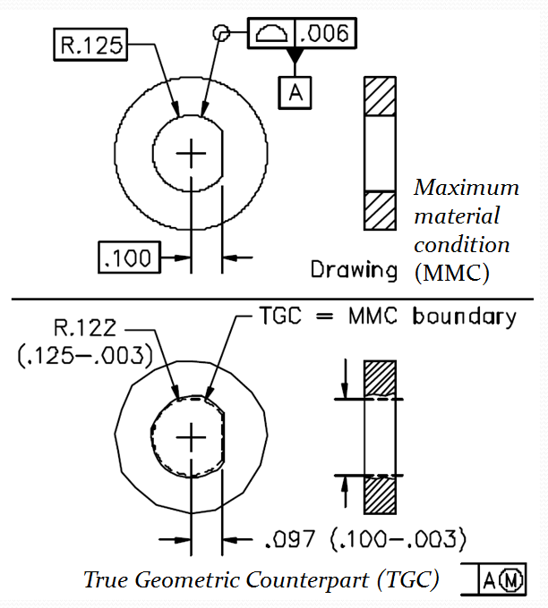
There is a type of feature that’s neither a sphere, cylinder, nor width-type feature, yet clearly has “a set of two opposed elements.” The D-hole shown in Fig. 2, for example, is called an “irregular feature of size” by some drafting manuals, while Y14.5’s own coverage for this type of feature is very limited. Although the feature has obvious MMC and LMC boundaries, it’s arguable whether the feature is “associated with a size dimension.” We’ll call this type of feature a bounded feature, and consider it a nonsize feature for our purposes. However, like features of size, bounded features are also subject to the principles of material condition modifiers, (I’ll explain this in a future post).
Symbols
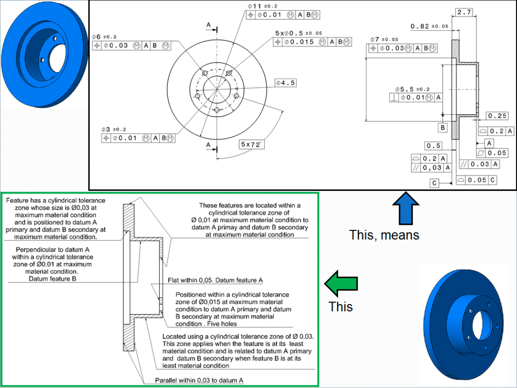
Of course depending on the spoken language in your country you are free to use any local language in order to put notes on your drawing, but if you work in an international environment English must be used too. Therefore the shortcomings of English as a main design specification language are essential. The lower view from Fig. 3 shows an attempt to control part features using mostly English. Compare that with the upper view, where GD&T symbols are used instead. Symbols are better, because of the following reasons:
- Anyone, regardless of his or her native tongue, can read and write symbols.
- Symbols mean exactly the same thing to everyone.
- Symbols are so compact they can be placed close to where they apply, and they reduce clutter.
- Symbols are quicker to draw and easier for computers to draw automatically.
- Symbols are easier to spot visually. For example, in Fig 3 upper and lower, find all the positional callouts.
In my following posts on GD & T topic, I’ll explain the applications and meanings for each GD&T symbol. Unfortunately, the process of replacing traditional words with symbols is ongoing and complicated, requiring coordination among various national and international committees. In several contexts, Y14.5 suggests adding various English-language notes to a drawing to clarify design requirements. However, a designer should avoid notes specifying methods for manufacture or inspection.

Leave a comment