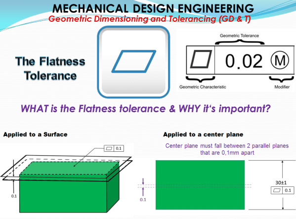
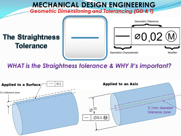
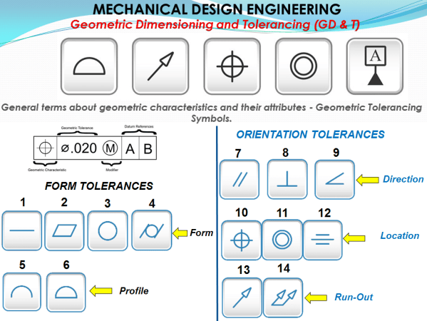
2 simple geometrical elements are responsible to describe any geometrical shape. These are the Straight Line and the Circle. If you connect a line with at least one external non-collinear point you get a plane. If you extrapolate a circle towards an external point in perpendicular direction to the center point you get a cylinder.... Continue Reading →
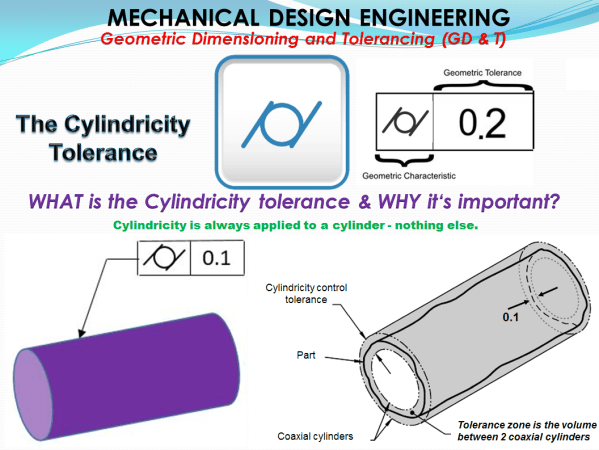
MECHANICAL DESIGN ENGINEERING – Geometrical Dimensioning and Tolerancing_What is the CYLINDRICITY tolerance?