All the time when you want to make sure something is accurately closed/sealed the parts that are joined in your mechanical assembly product must have a specified restriction for how tight that closure must be. For this reason is essential that these parts are designed by default with such important specification which in Mechanical Design Engineering is called FLATNESS. The standards which are famous for GD &T terms are of course the DIN EN ISO 1101 and ASME Y14.5M-2009). So let´t talk about it. What is FLATNESS?
Description
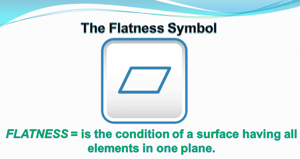
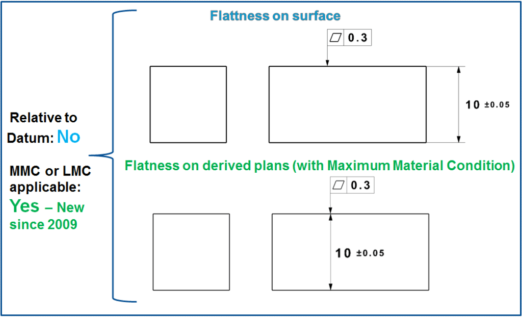
Flatness tolerance extends the straightness tolerance by one dimension. It is a straight forward geometrical condition of a surface in which all the points must be in one plane. Flatness is applied to an individual surface and it does not need to be related to a datum. It is always less than the dimensional tolerance associated with it.
The limitation of flatness deviations is necessary for many geometric elements, e.g. for clamping or support surfaces of workpieces, for dividing surfaces of housings or for sealing surfaces with flat seals. Often a flatness tolerance is necessary for reference surfaces.
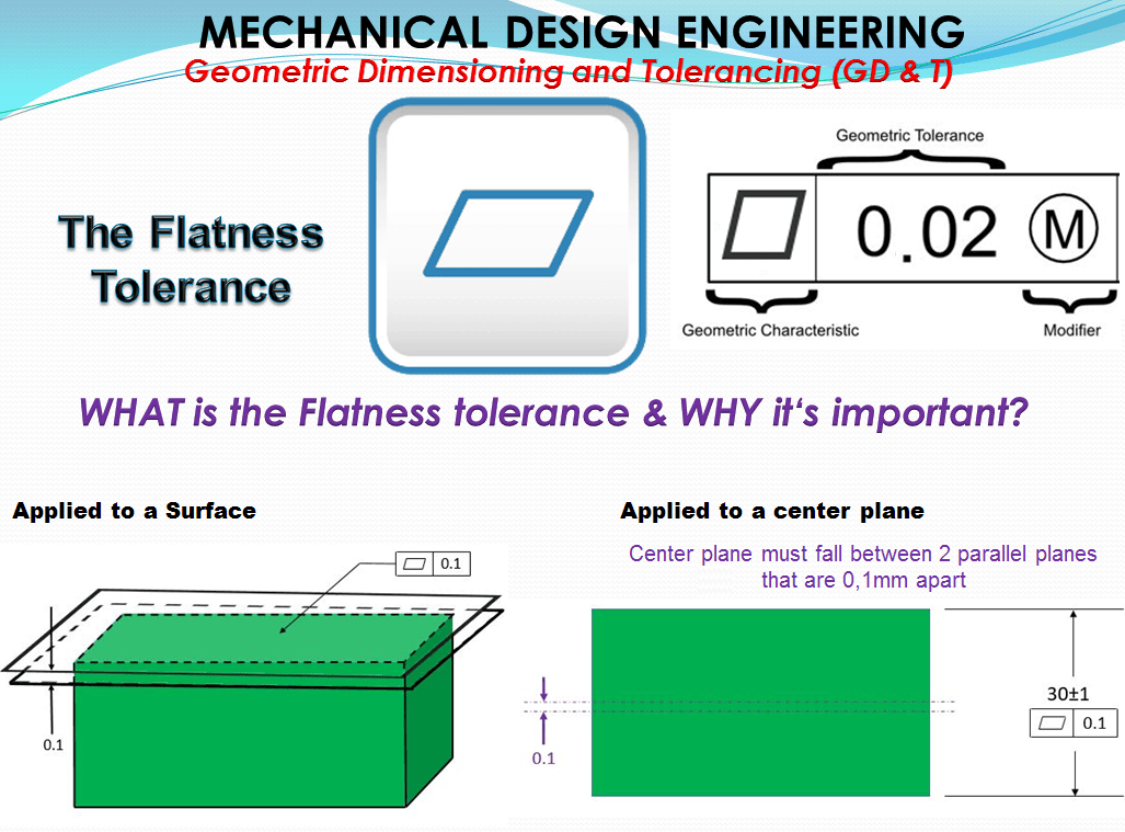
Symbol: The flatness symbol is a parallelogram, so to speak a “rectangle in an oblique view” specified in the left side compartment of the feature control frame.
Flatness is a common symbol that references how flat a surface is regardless of any other datum or features. It comes in useful if a feature is to be defined on a drawing that needs to be uniformly flat without tightening any other dimensions on the drawing.
A feature control frame is attached to the surface with a leader or extension line, in this case the tolerance applies to a single nominally flat feature.
The flatness tolerance can, like the straightness tolerance, refer not only to real planes (Figure 2.), but also to derived planes (middle-, symmetry planes). However, the flatness of derived planes is usually only found in connection with the maximum material condition.
When a feature control frame with a flatness tolerance is applied with a size dimension, the flatness tolerance applies to the median plane for a non-circular surfaces. The derived median plane is composed of all the midpoints of the actual local size. The median plane is not necessarily flat. The flatness tolerance may be used to control the form of derived median plane, similar with the straightness tolerance which may be used to control the form of the derived line.
For a width-type feature of size, Rule #1 automatically limits the flatness deviation of each surface.Thus, to have any meaning, a separate flatness tolerance applied to either single surface must be less than the total size tolerance. A flatness tolerance feature control frame associated with a width dimension replaces Rule #1’s requirement for perfect form at MMC with a separate tolerance controlling the overall flatness of the width-type feature.
According to ASME Y14.5M-1994, the Rule #1 decrees that: “Where only a tolerance of size is specified, the limits of size of an individual feature prescribe the extent to which variations in its form—as well as in its size—are allowed”
Alternatively, the “center method” may be applied to a flatness tolerance at MMC or LMC, but there’s rarely any benefit to offset the added complexity. Unmodified, the tolerance applies RFS and establishes a central tolerance zone within which the feature’s derived median plane shall be contained..
Maximum Material Condition (MMC) further specifies the flatness by controlling the size of the feature in addition to the allowed “bend” of the surface.
Tolerance zone
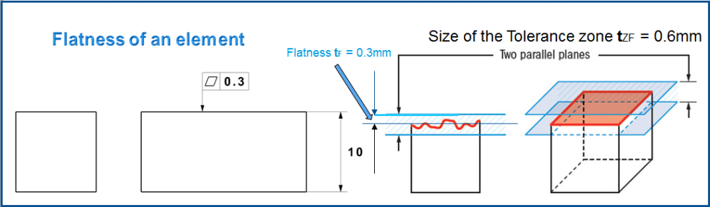
The tolerance zone It is defined by 2 sets of parallel planes at the distance of the flatness tolerance value tF (see fig 3) on each side of the referenced surface, where the entire referenced surface must lie. As long as no additional restrictions are specified, it extends over the entire tolerated area.
The tolerated area may show any deviations within the size of tolerance zone tZF. Typical flatness deviations can correspond to the same deviation like for straightness (see figure 5 from my previous post about straightness); In addition, there are spatial deviations in flatness such as the arching (c) and twisting (d) (as shown in fig.4 below), which occurs, for example, at the deformation of torsionally insufficient rigid component elements.

If the curvature or arching is convex (as sketched at b and c ) or the plane is twisted (d) (Fig 4) then when it is placed on a flat counter-plate, the surface wobbles. Such elements are usually unusable as reference surfaces.
A flatness tolerance cannot control whether the surface is fundamentally concave, convex, or stepped; it controls just the maximum range between its highest and lowest undulations.

For all these flatness deviations the controlled surface must lie within the tolerance zone limits over its entire length, meaning that it may touch it, but not break through.
WHEN is the Flatness tolerance used?
Flatness tolerance is used when you want to constrain the amount of waviness or variation in a surface without tightening the dimensional tolerance of said surface. Usually, flatness is used to give a surface an even amount of wear or for sealing properly with a mating part. Commonly used on a fixture that must mate flush with another part without wobbling, but where orientation is not important.
The flatness feature control frame may be applied only in a view where the element to be controlled is represented by a straight line. This specifies a tolerance zone bounded by two parallel planes separated by a distance equal to the tolerance value, within which the entire feature surface shall be contained.
This is how Flattness tolerance works:

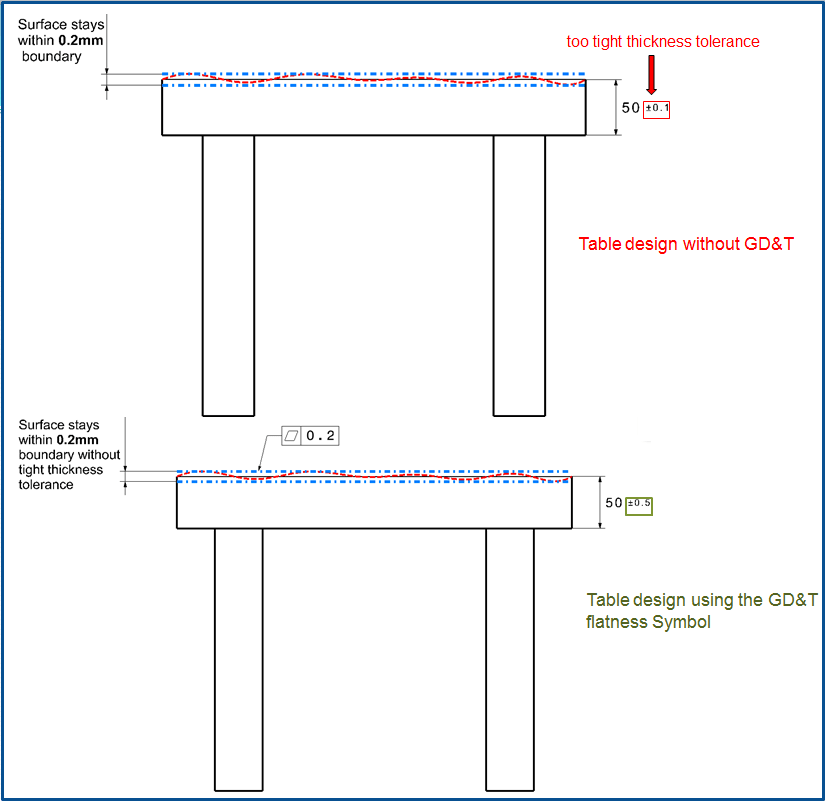
For example: If you want to make sure that a tabletop is perfectly flat, if you did not have a flatness callout, you would have to constrain the height of the table very tightly to make sure that the entire surface is straight. With flatness, you can allow the table to be flat without constraining the tabletop thickness very tight. (You would be rejecting tables that were good thicknesses and normally in spec if using GD&T).
Gauging/Measurement
Flatness can be measured using a height gauge run across the surface of the part if only the reference feature is held parallel. You are trying making sure that any point along the surface does not go above or below the tolerance zone. Modern CMM’s are best for measuring the part as they can create virtual planes that the true surface profile can be compared to. This is a 3D measurement so points must be measured across the length and width of the part to ensure the entire surface is in tolerance. Flatness cannot be measured by simply placing the part on a granite slab and running a height gauge or microheight over it. This would be measuring parallelism instead as you are fixing the bottom of the part as a datum.

The limit deviation is equal to the flatness tolerance tF. As with straightness, the flatness deviation (at the MMC) is defined as the smallest possible distance between 2 parallel boundary planes that enclose the tolerated surface between them. It can be imagined as the largest remaining distance between the toleranced plane and a test plate that fits as closely as possible. However, measuring these planes causes more difficulties than straightness. A measuring device must scan a sufficient number of points in order to be able to detect the highest and lowest points. Without a measuring device, only those surfaces can be checked with sufficient accuracy that do not wobble when placed on a test plate.The testing device has For example, a dial gauge put into the measuring plate as shown in figure 4 above.
Including all form deviations of flatness tolerance shows that there is a relation between flatness tolerance and straightness deviations as follows: “The deviation from the straightness of any straight line within the tolerated plane cannot be greater in the tolerance direction than the flatness tolerance.” This sentence cannot be reversed. The flatness deviation can very well be greater than the largest straightness deviation to be determined in the plane. This is the case with twisting (see fig 4 d)
Relation to other GD & T Symbols
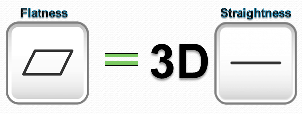
Flatness is the 3D version of surface straightness – Instead of the tolerance zone between two lines; the tolerance zone exists between two planes.
Final Notes
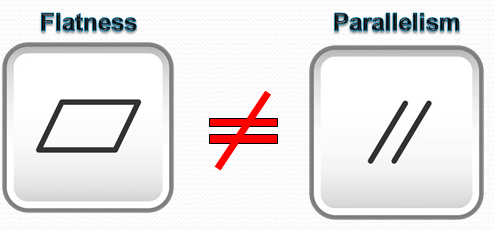
Flatness is not the same as paralellism. Parallelism uses a datum to control a surface while flatness does not. Think of a table with two missing legs at an angle to the floor. The tabletop may be within flatness tolerance but would not be parallel to the floor.

What is the difference between the measurements and testing and also the difference between the straight and flatness
LikeLike
Good question, thanks for asking ;-), well…. when you measure something you check if in reallity that feature is indeed acurate enough as specified on the drawing, for instance you measure the length of a screw.
Yet when you do a test that means you check if that screw with that length will actually work for what was intended (could be too long or could be too short than previously thought)
In short by measurement you check the feature and by testing you check the functionality., and that’s the difference.
Regarding your second questions the answer is simple
With Straightness you measure a straight edge or line, it’s a 1D (dimensional) measurement.
With Flatness you measure a flat surface, it’s a 2D (dimensional) measurement.
LikeLike