2 simple geometrical elements are responsible to describe any geometrical shape. These are the Straight Line and the Circle. If you connect a line with at least one external non-collinear point you get a plane. If you extrapolate a circle towards an external point in perpendicular direction to the center point you get a cylinder.
If you continue to add external points and connect the basic elements made from lines and circles you get objects of complex shapes. So before to understand how mechanical design of things works you must understand the 2 basic geometrical elements first.
The same as the plane is the 3D for the Line, also the cylinder is the 3D of the circle. In this post let´s have a look at the CYLINDRICITY.
Description
Cylindricity is a geometrical condition of a machined part with surface of revolution, a 3-dimensional tolerance that controls the overall form of a cylindrical feature to ensure that it is round enough and straight enough along its axis. Cylindricity is independent of any datum feature, the tolerance needs to be less than the diameter dimensional tolerance of the part. Cylindricity essentially forms a perfect cylindrical boundary around the object that the entire 3-Dimensional part must lie in.
We can also say that the Cylindricity tolerance extends the Circularity tolerance with 1 dimension, namely: the length. Thus Cylindricity tolerance applies both longitudinal and circular element of the surface and controls the entire surface of a cylinder and is applied to an individual surface.
Most of measurement characteristics valid for Circularity egually apply to Cylindricity too. (YOU CAN UNDERSTAND THE CYLINDRICITY ONLY IF YOU UNDERSTAND THE CIRCULARITY).
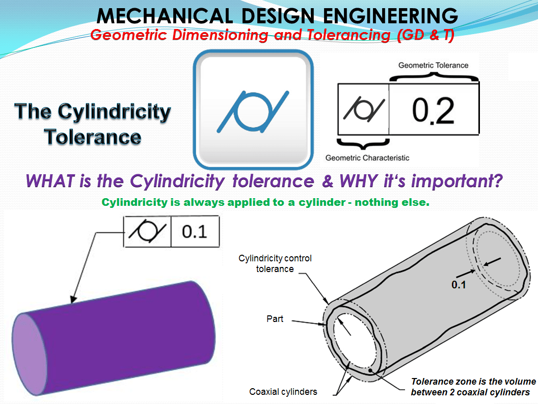
Symbol: The Cylindricity symbol is a circle between 2 parallel slashes, imaginable as the addition of parallel surface lines to the circular shape. The Cylindricity symbol is used to describe how close an object conforms to a true cylinder.

The Cylindricity tolerance call out
The cylindricity tolerance is practically prescribed only for real cylindrical surfaces (Outer or Inner), it does NOT apply for derived elements such as axis and center lines. Therefore the tolerance control frame leader must not be placed on the dimension line.

Tolerance zone
A Cylindicity Tolerance is a composite control of form that includes circularity, straightness, and taper of a cylindrical feature. A cylindricity tolerance specifies a tolerance zone bounded by two concentric cylinders whose radii differ by an amount equal to the tolerance value tC (Figure 3). The entire feature surface shall be contained within the tolerance zone (between the two cylinders). The tolerance zone cylinders may adjust to any diameter, provided their radial separation remains equal to the tolerance value. This effectively removes feature size from cylindricity control. As with circularity tolerances, a cylindricity tolerance must be less than half the size tolerance to limit multi-lobed form deviations. Since neither a cylindricity nor a circularity tolerance can nullify size limits for a feature, there’s nothing to be gained by modifying either tolerance to MMC or LMC.

Cylindrical form deviation: the cylindricity deviations can be imagined as overlaps between Circularity, Straightness and Parallelism. Depending on manufacturing process, for short cylinders the circularity form deviation often predominates on slender cylinders versus the deviations in length.
Included deviations: The tolerance zone of cylindricity is the same like the one for circularity on front view and the same with the straightness in the side view (Fig 3). therefore the following statement can be said:
The circularity deviation (dR) of each individual cross-sections as well as the straightness deviation (dS) of the surface lines , cylinder axis included, can not be bigger than the Cylindricity tolerance tC.

The parallelism deviation dP of the surface lines with the axis which can have the value tC, can reach 2tC on the opposite surface lines. The parallelism deviation is a position deviation and occurs when the tolerated cylinder turn out to be a conical.

For length deviations the typical idealized cases are shown in Fig. 6

The shape d in fig. 6 is the only one with an odd axis. This can happen as result of overlaying with roundness deviations which occur for examples due too machine vibrations, screw-type bodies or multiple other things during the manufacturing process.
WHEN is the Cylindricity tolerance is used?
The constraints to cylindricity deviations are needed in the functionality of numerous rotating parts such are gearing elements. Cylindricity tolerance is applied where cylindrical part features must have good circularity, straightness and taper.
Cylindricity is a fairly common callout for shafts, pins and any critical cylindrical element. When a part needs to be both round and straight along its axis, such as a sliding shaft, or a dynamic locating pin, cylindricity is usually called out. You will see this GD&T symbol very often in automotive drawings and mechanical systems.
Example 1 = Cylindricity application over a limited length or area
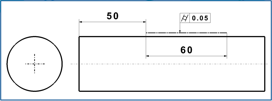
Some designs require form control over a limited length or area of the surface, rather than the entire surface. In such cases, draw a heavy chain line adjacent to the surface, basically dimensioned for length and location as necessary, as shown in Fig. 7. The form tolerance applies only within the limits indicated by the chain line.
Example 2 = Cylindricity tolerance applied to a shaft
In the cylidricity tolerance zone, the cylindrical surface must lie between two concentric/coaxial cylinders ,these are based on given cylindricity tolerance zone of 0.05 as shown in fig.8. The surface must lie within the given tolerance limits.

Example 3 = Controlling the cylindricity tolerance without and with the GD & T Symbol
If you had a bushing that was to be pressed into a housing, the bushing would take the form of the housing bore when inserted. To ensure that the bushing maintains its round shape, and wears evenly along its surface, the housing bore needs to be very cylindrical. To do this without GD&T you would need very tight dimensions on the diameter of the bore, which may be very hard to control when being machined (and expensive).
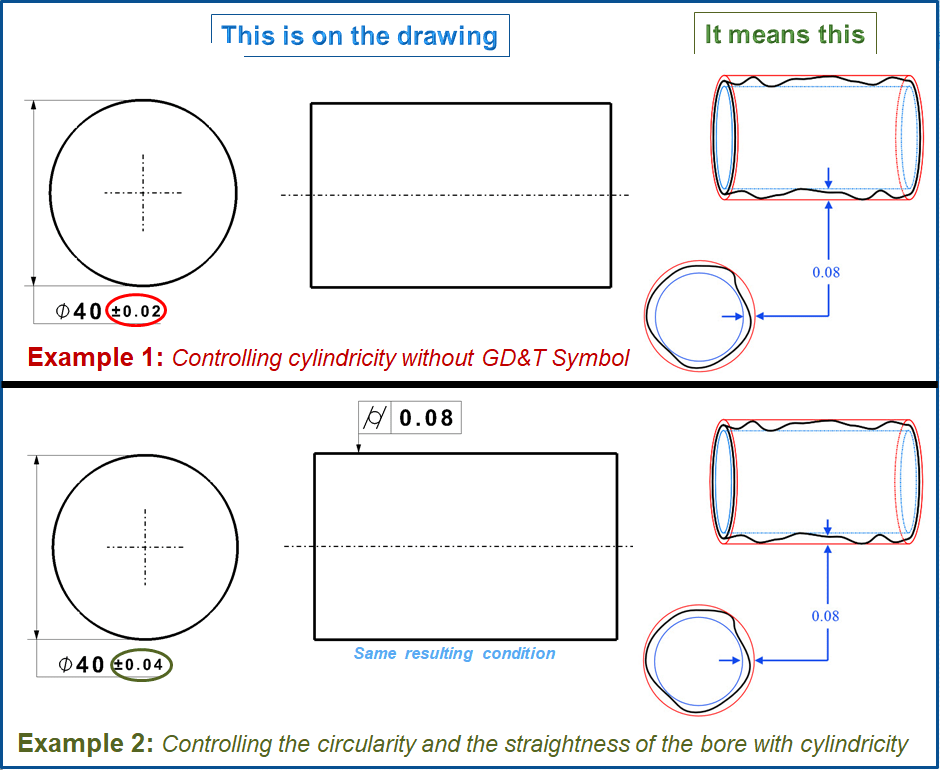
This GD&T control allows the diameter tolerances of the part to be opened up much larger, and better controls the entire length of the bore. You can now accept a much broader range of hole sizes as long as the cylindricity is met.
Gauging/Measurement
Cylindricity is measured by constraining a part on its axis, and rotating it around while a height gauge records the variation of the surface in several locations along the length. The height gauge must have total variation less than the tolerance amount.
Limit deviation and test: The Limit deviation is equal with cylindricity tolerance value (tC). An accurate cylindricity deviation measurement taking into consideration the least material condition (LMC) using conventional measuring devices is hardly possible. There are approximations that can be used to determine the Straightness, Circularity and Dimensional deviations , but all these – depending on type, size and position -can lead to falsified results. The individual deviations do not simple overlap additively. It applies only with a minimal probability of being exceeded.
Therefore a correct cylindricity deviation measurement should be always done with measuring gauges respectively with form testing devices as shown in fig. 10

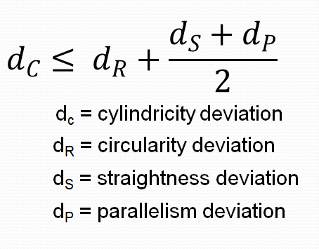
If such devices are not available or the workpiece can not be placed on the device, then on the drawing instead of cylindricity it is better to specify functional characteristics based on circularity, straightness and parallelism and determine the cylindricity deviation with the formula as shown.
Or another possibility is to specify a functional characteristic based on total run-out which can be used with the available measuring instrument.
Relation to other GD& T Symbols

Cylindricity is the 3-Dimensional version of circularity along an entire cylinder length. While circularity only is concerned with individual measurements around the surface in one circle, cylindricity takes into account how straight the axial portion of the cylinder is. Thinking of stack of coins, cylindricity would measure to make sure that the entire stack is straight up and that every coin is round. Circularity would only be measurements of the roundness of the individual coins.
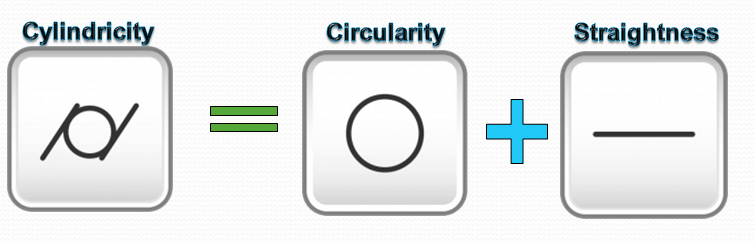
Cylindricity is a merger of circularity and surface straightness.
Final Notes
Statistical tolerances: Because cylindricity specifies the form of the surface, it must be considered when calculating a statistical tolerance stack. For example, if you have a part with a diameter and cylindricity callout, you must input both into your statistical stack since the cylindricity can contribute to a large part envelope than just the diameter tolerance alone. There are different theories on doing this and how to implement it; however, it can make a slight impact on skewing the results higher. Normal tolerance stacks do not require this since due to the envelope principle; the maximum radial envelop cannot exceed your maximum diameter tolerance due to rule #1 of GD&T.

This blog is loaded with valuable information, thanks for sharing.
LikeLike
You’re welcome. I’m glad to know this is helpful for you 😉
LikeLike
You’re welcome. It’s my pleasure.
LikeLike
Hello. I don’t know if you maintain this blog or not, so I’ll try anyway. In example 3 of Cylindricity, the text before the pictures says, “To do this without GD&T you would need very tight dimensions on the diameter of the bore, which may be very hard to control when being machined (and expensive).” However, in the Examples below, the diameter tolerance in example 1 is wider than the equivalent in example 2, which contradicts the text. Or am I misunderstanding both? Besides that, I would say really nice approach: one term, one dedicated page, but very detailed. Great job and useful results.
LikeLike
Hello, yes of course, I maintain and regularly publish new stuff on this blog. Your comment is highly appreciated, thank you so much.
I’ve just checked the text you are refering to and yes you are right, while editing this by mistake I swaped the images in example 3, it should be the other way around exactly as you’ve noticed. I’ve just corrected that and now we have the right picture.
In priciple this approach is in general applicable to other types of tolerances not only cylindricity. I mean like in case of cylindricity of course is much easier to control the dimension if the tolerance value is a bit larger. Otherwise if we just put dimension there without specifing the Cylindricity tolerance, this could be also possible but in that case we will need measument equipment of super high measumement accuracy and this will definitelly increase manufacturing costs, which obviously is not necessary in most cases.Hence, it’s much better to specify cylindicity of wider values.
Thank you again and if you notice similar errors on my posts or if you just what to know more, don’t hesitate to let me know.
LikeLike
I’m glad to hear that. As I said, I like the approach. Not a lot of everything dumped in one place, but a systematic description of one concept in almost painful detail. I’m also glad I wasn’t wrong, doubly so. I was a little worried that I had no clue, so I’m a little more at ease now. And of course, the mistake will be corrected. Anyway, bravo for the good work.
LikeLike
Thank you very much. It took me a while to create these posts, It’s part of my academic background and work experience as mechanical engineer since 2003. All these are, I would say general concepts covering the most frequent cases we encounter with GD & T practice in manufacturing. However, of course there could be special cases in which things get complex and that could be not be easily explained by simple appoaches as I tried to descibe in my articles here.
I usually check multiple times everything before posting but it may happen that some little errors in text could occur. Anyway I am always greatful to receive comments like yours. It means my work is visible and this only motivates me to keep this blog active.
It’s been a while since I last posted on GD & T topics , I have a lot more to share but first I wanted to present the Tolerance types. New material on GD & T topics will be published soon.
Again many thanks for reading my blog.
LikeLike