In every new product development process there are different stages to go through until the first official release is available for mass production. In early stages of product development you have the opportunity to test as many prototypes as possible, nothing must be strictly defined; however after few iterations, many tests and approval processes you must define the final product design for the mass production. Here you already must be very specific and you must accurately define how your product will actually work. For this you must mandatory apply GD & T rules. But to apply GD &T you also MUST 1st of all understand how it works and then master the terms so that your product will be a reliable object which will offer a great User Interface and User Experience.
Basically GD & T consist in applying 14 geometrical tolerances in different combinations. In order to master your product design and make sure it will reach its goal, you must understand how these 14 terms -as defined by DIN EN ISO 1101 (or ASME Y14.5M-2009)- work. I will present all of them each with a dedicated article. The 1st one I am going to share below is: THE STRAIGHTNESS
Description
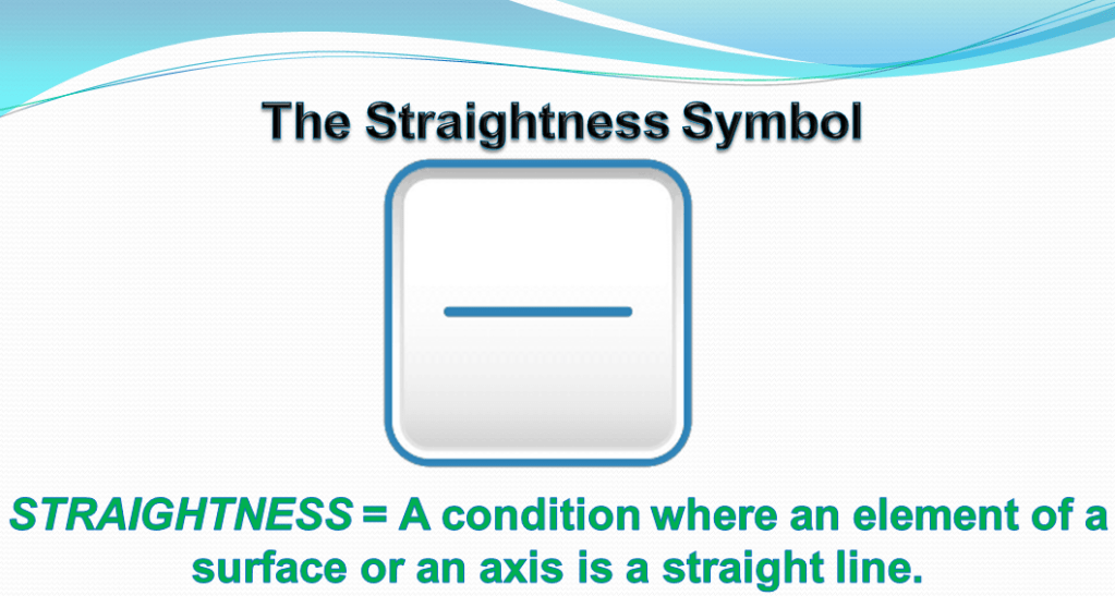
Straightness is a 2-dimensional geometric tolerance; it is a condition where one line element of a surface or the derived median line/axis must lie in a straight line, this condition being specified by a value which defines the size of the tolerance zone. A straightness tolerance ensures that a geometric element which geometrically represents an ideal straight line, at the execution of the workpiece does not exceed a certain deviation from the ideal straight line. (colloquially speaking: that a line is sufficiently straight).
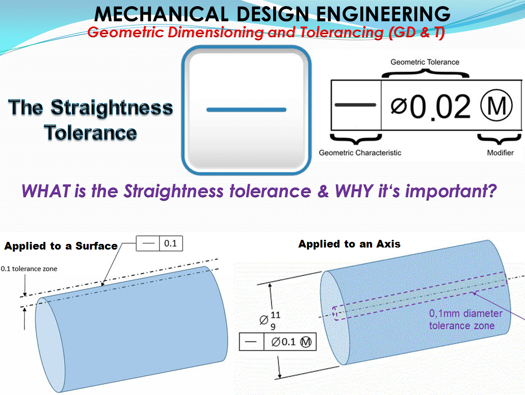
Symbol: The symbol for that is a horizontal line in the left compartment of the feature control frame, as shown in figure 1.
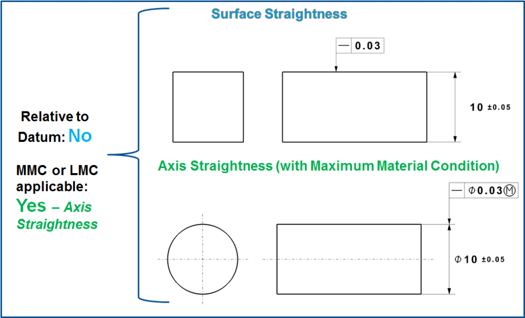
Straightness actually has 2 very different functions in GD&T depending on how it is called out.
In its normal form or Surface Straightness, is a tolerance that controls the form of a line somewhere on the surface or the feature.
Axis Straightness is a tolerance that controls how much curve is allowed in the part’s axis. This is usually called out with an included call to maximum material condition.
Both callouts are very different from each other!
Note:
- Surface Straightness is called out on the surface of the part.
- Axis straightness is called out next to the size dimension of the axis.
Surface Straightness:
The standard form of straightness is a 2-Dimensional tolerance that is used to ensure that a part is uniform across a surface or feature. Straightness can apply to either a flat feature such as the surface of a block, or it can apply to the surface of a cylinder along the axial direction. It is defined as the variance of the surface within a specified line on that surface.
Where a straightness tolerance feature control frame is placed (with a leader directed to a feature surface or attached to an extension line of a feature surface), the tolerance controls only line elements of that surface. The feature control frame may only appear in a view where the controlled surface is represented by a straight line.
Axis Straightness:
The form of straightness that controls the central axis of a part is sometimes referred to as Axial Straightness. This tolerance callout specifies how straight the axis of a part is (usually a cylinder). By definition, axis straightness is actually a 3D tolerance that constrains the center axis of the part preventing it from bending or twisting too far.
Maximum Material Condition (MMC) further specifies this by controlling the size of the feature in addition to the allowed “bend” of the axis. Although a control of the axis, when MMC is called out, the entire part is used to determine if the tolerance has been met with a Go-Gauge. (See Gauging Section below).
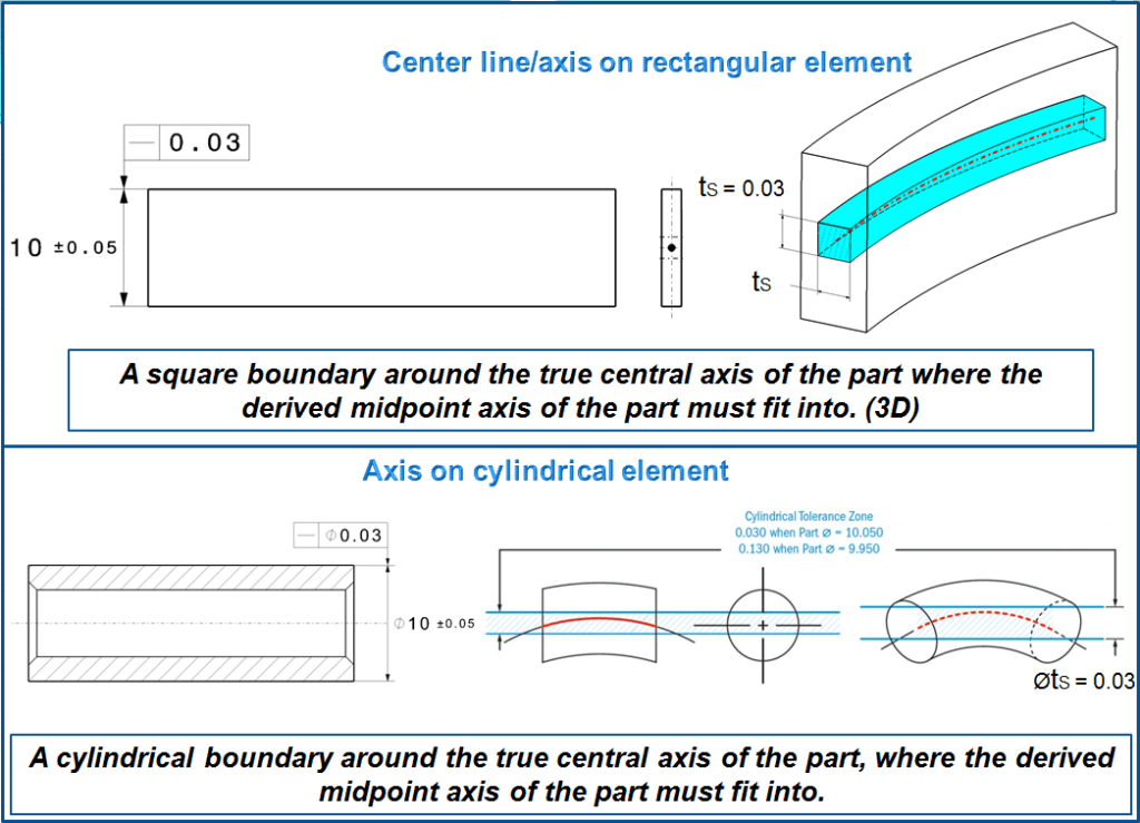
Tolerance zone
It is defined by 2 parallel limit lines (possibly also limit planes) at the distance of the straightness tolerance tS (Figure 3) or by a limit cylinder with ØtS (Figure 4). With all form tolerances, as the tolerance zone plane sweeps the entire feature surface, the surface’s intersection with the plane shall everywhere be contained within the tolerance zone (between the 2 lines). Within the plane, the orientation and location of the tolerance zone may adjust continuously to the part surface while sweeping.
a) Surface straight line
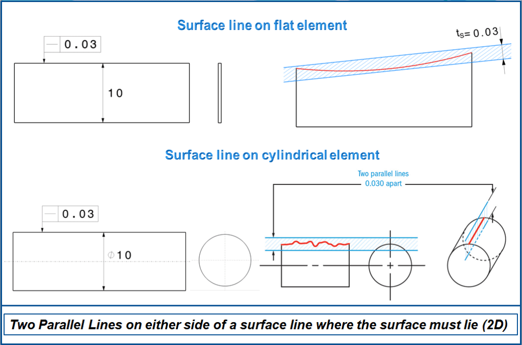
Of a Planar Feature — The orientation and sweep of the tolerance zone plane is not explicitly related to any other part feature. The plane is merely implied to be parallel to the view plane and swept perpendicular to the view plane (toward and away from the viewer). Again, the zone itself may tilt and shift within the tolerance zone plane to accommodate gross surface undulations. Where it’s important to relate the tolerance zone plane to datums, specify instead a profile of a line tolerance.
Of a Cylindrical or Conical Feature—The straightness tolerance zone plane shall be swept radially about the feature’s axis, always containing that axis. (Note that the axis of a cone isn’t explicitly defined.) Within the rotating tolerance zone plane, the tolerance zone’s orientation relative to the feature axis may adjust continuously.
b) Derived straight line/Axis
Here the axis of the outer jacket (not that of the hole). The actual axis will be metrologically derived from the geometric element, on the dimension line arrow where the tolerance control frame arrow stays.
Straightness tolerance is applied in the view where the elements to be controlled are. The feature control frame needs to be attached to the surface with an extension line or a leader when a surface needs to be controlled.
Straightness Tolerance for a Cylindrical Feature
A straightness tolerance feature control frame placed below or attached to a leader-directed callout or dimension pertaining to the feature (or attached either side or either end of the frame to an extension of the dimension line pertaining to a feature of size) associated with a diameter dimension, replaces Rule #1’s requirement for perfect form at MMC with a separate tolerance controlling the overall straightness of the cylindrical feature.
According to ASME Y14.5M-1994, the Rule #1 decrees that: “Where only a tolerance of size is specified, the limits of size of an individual feature prescribe the extent to which variations in its form—as well as in its size—are allowed”
Unmodified, the straightness tolerance for axis applies RFS (Regardless of Feature Size) and establishes a central tolerance zone, within which the feature’s derived median line shall be contained.
In principle, the tolerance zone is always perpendicular to the tolerance arrow; however, their real orientation follows the minimum condition. The tolerated straight line, (both for flat surface and cylindrical), must lie within these limits over its entire length, meaning that it may touch it, but not break through.
WHEN is the Straightness tolerance used?
Surface
Commonly used for sealing surfaces or surfaces that mate with another part. For example, hydraulic channel cover in a transmission would need to make steel on steel contact in order to seal off the open hydraulic channels and maintain pressure. With a straightness call out you can specify which lines on the surfaces are most critical to making sure the pressure is maintained.
Surface Straightness Examples:
A steel bar is welded in a T pattern to another steel bar. If you want to make sure that the surface of the tube is always uniform, where the weld occurs, you would need to either greatly tighten the dimensional diameter of the tube, (which would be very costly for such a simple part!), or callout straightness along the mating surface.
This is how Straightness tolerance on surface looks like:
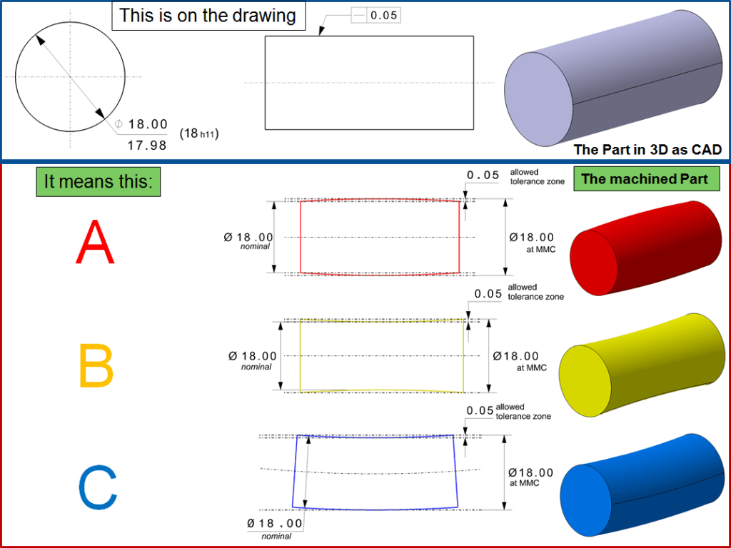
On the figure 6 shown above, each longitudinal element of the surface must lie between 2 parallel lines 0.05 mm apart where the 2 lines and the nominal axis of the part share a common plane. The feature must be within the specified limit of the size. The boundary of the perfect form at Maximum Material Condition (MMC) should be Ø18.00 (18h11) tolerance limit defines the boundary at MMC, see “h11” limit from the chart (ISO Shaft Tolerances (ISO 286-2)(3mm-400mm)). For the machined part A, B, and C their straightness tolerance must not exceed the limits of the part size feature.
This tolerance is used to ensure the straightness of a certain tight area on the workpiece, the function of which requires direct contact with other parts, e.g. as a runway, as a stop with line contact or the like. Some other frequent examples of surface straightness are presented below.
a) Surface line on the edge
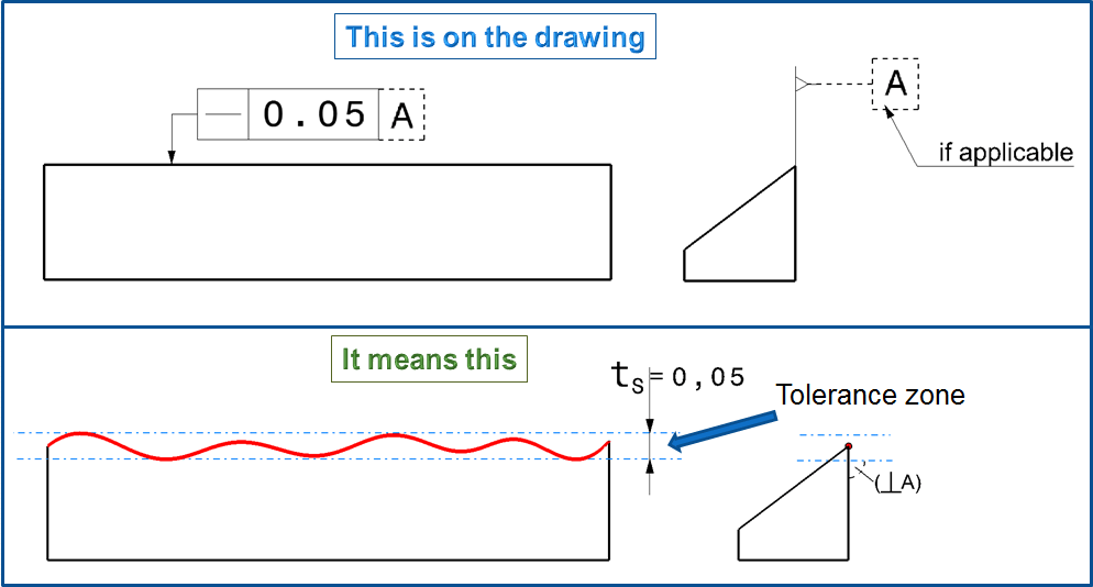
The straightness of the prism edge is only restricted in the direction perpendicular to the tolerance arrow, but not across it (e. g. with a lateral curvature of the prism). The tolerance limits can therefore be thought of as planes (instead of lines) or we can consider that the tolerated edge is projected onto the tolerance limits lying on the drawing planes.
Note: The case here is that the unambiguous measurement may require a reference specification even in the case of a form tolerance, as indicated by dashed lines. Without the reference, it is not clear whether the prism piece is to be placed on the lower surface for measurement or on the side surface (Such a reference corresponds to the primary reference in reference systems, which defines the main orientation of a component)
b) Surface lines on a cylinder
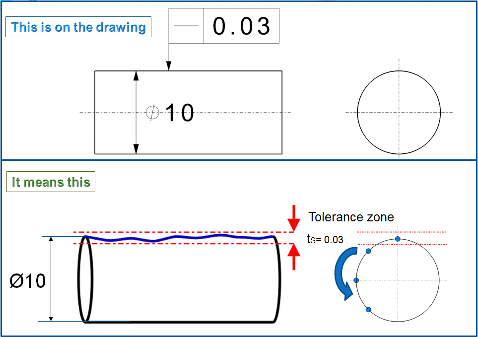
The tolerated surface line is the one initially lying on the top of the drawing. However, since the workpiece is rotationally symmetrical, this line cannot be determined individually, that means the specification covers all surface lines and thus implicitly also the axis of the cylinder. Basically means:
Straightness of surface lines and axis = The straightness deviation of the axis of a circular profile cannot be greater than the greatest straightness deviation in the surface lines.
c) Surface lines of a discontinuous cylinder.
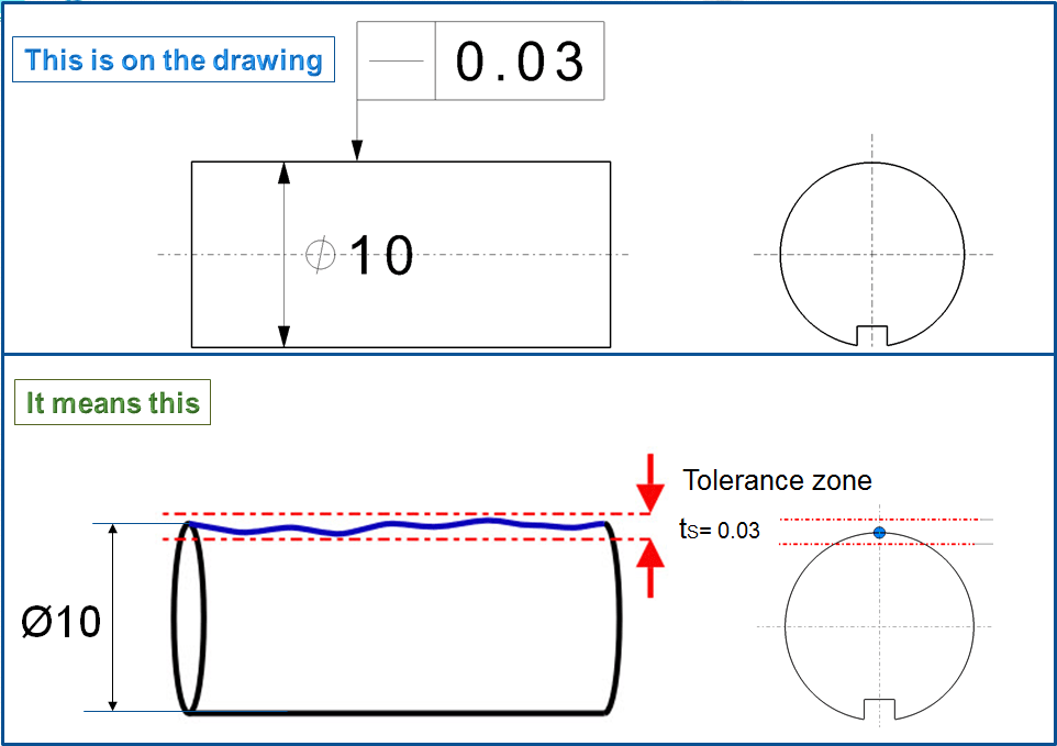
In the case of the grooved cylinder, the toleranced surface line is precisely defined; therefore, the straightness tolerance only applies to the surface line at the top (That could e.g. be useful because the one-sided groove can cause a greater distortion in the direction of the groove middle plane.) If, on the other hand, all surface lines are to be tolerated, for clarity purposes the addition “all surface lines” must be written on the tolerance frame.
d) Straight lines within a plane
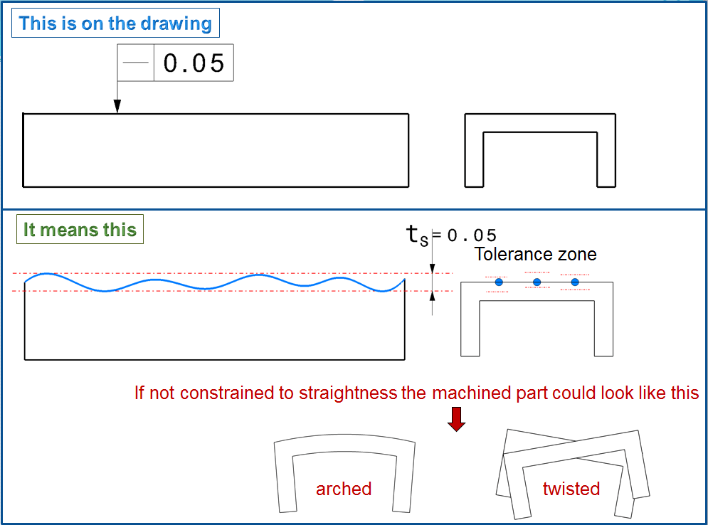
This is a special case. Each individual straight line that lies parallel to the plane of the drawing in the view where the straightness tolerance is entered (e.g. on the left as shown here) must be straight on its own. For testing it could be for example put on a straight edge in different positions, but always in the perpendicular direction of the drawing planes with the tolerance entry. (If this would not be like that, then in this case we would also have to check across and diagonally; with this it would be something similar like a flatness tolerance). Such a specification only makes sense if the function of the surface only requires the straightness of individual lines in a certain direction, but not the flatness of the entire surface.
One example is the carrier (runner) of a printer, which is guided by a round column and also runs on a metal sheet with a support roller; this sheet only needs to be sufficiently straight in the running direction. (Note: A reference could also be useful here, as shown at the example a-see Fig.7)
e) Straight lines within a plane (as variant to d)
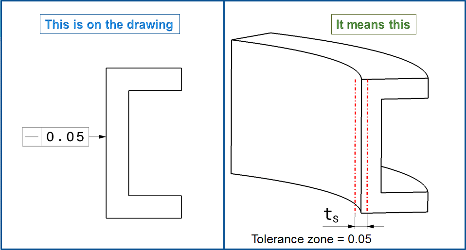
The profile e – it may be extruded or formed- should only be straight in any profile cross-section, regardless of the straightness in the longitudinal direction. In summary the examples of d and e, can be perceived as:
Straightness tolerance within a flat surface = If the straightness is only to be tolerated in a certain direction in a flat surface, then the test direction is parallel to the plane of the drawing where the tolerance arrow is entered; the tolerated area is usually perpendicular to the drawing plane.
Axis and Centerlines (Derived Elements)
This tolerance mode is used to ensure the straightness of a rotationally or mirror-symmetrical geometric element overall in its longitudinal direction. For clear identification, the tolerance arrow must be placed on the dimension arrow that measures the form element from which the axis or center line is to be derived. The following examples, the cases relate to external elements (“shafts”). But they apply accordingly to interior elements (“holes”) as well.
Used mainly on pins or cylindrical surfaces which must be installed with clearance into a bore or hole. The straightness callout ensures that even in the Maximum Material Condition; the part will still fit its mating hole or section. Straightness is commonly used to control the curve of some parts that may be prone to bending during manufacturing.
Axial Straightness with MMC Examples:
A boss pin on an engine housing is inserted into the chassis of a car to set the alignment before being bolted in. The pin is always in the correct position, however since it is so critical the dimension of the chassis mating hole is very tight. To ensure that this pin is always a correct fit for the hole, straightness is called out on the axis with maximum material condition.
An example of the Straightness at MMC (Maximum Material Condition) using the imperial measurement system (values in inch) is shown figures 12 & 13 below:
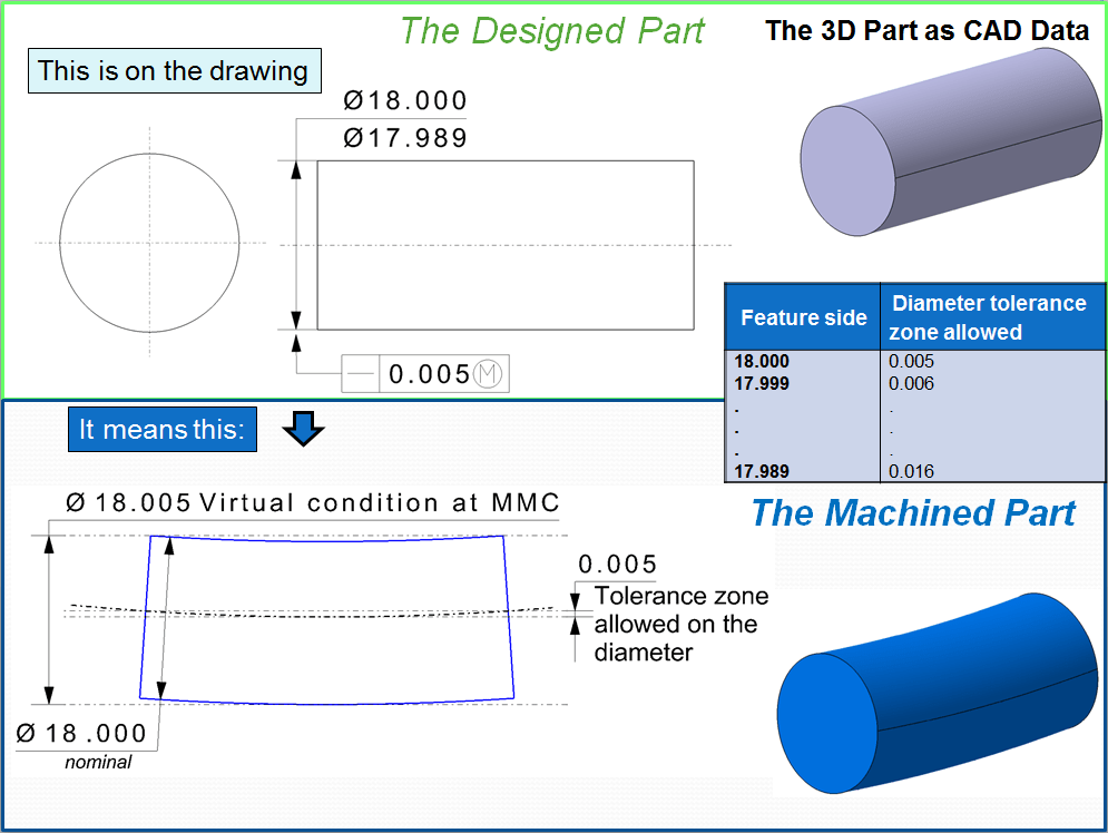
The derived median line of the feature actual local sizes must lie within a cylindrical tolerance zone of the 0.005 inch diameter at Maximum Material Condition (MMC). As each actual local size departs from Maximum Material Condition an increase on the nominal diameter of the cylinder tolerance is allowed which is equal to the amount of the specified limit. Each circular element of the part surface must be within specified tolerance limit of the given size.
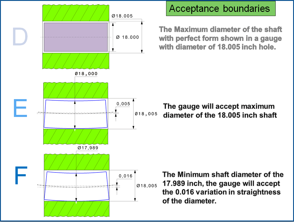
The meaning of the acceptance boundary are as shown in Fig.13
Some other frequent examples of straightness in metric system (values in millimeters) for derived elements are presented as follows:
a) Axis of a continuous circular profile
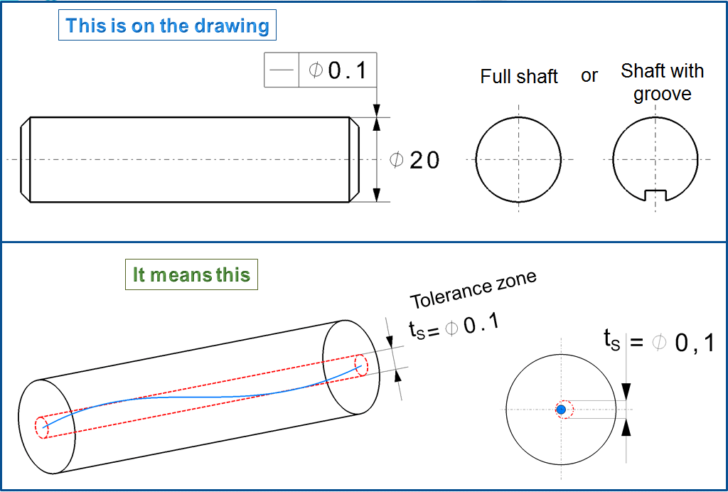
Here only the straightness deviation of the axis is restricted, but not that of the surface lines. The cylinder could for example be spherical, even if the axis is straight. Mostly it is required that the straightness of the axis is tolerated in all directions. Then a diameter symbol (Ø) is placed in front of the tolerance value.This means that the tolerance zone no longer lies between parallel straight lines or planes, but rather forms a circular cylinder with a diameter tS. The entire length of the toleranced axis must lie within this cylinder. If you omitted the diameter symbol (Ø) in front of the tolerance value 0.1, the result itself would not change, because due to the rotational symmetry you would have to check the straightness in all directions. But for the sake of clarity, however, you should always use the diameter symbol (Ø).
b) Axis of an interrupted circular profile (shaft with groove)
If the circular profile, whose axis is tolerated, is interrupted or the like. (e.g. through a groove or a transverse hole), then the diameter symbol (Ø) is absolutely necessary so that the straightness tolerance applies in all directions (all around). The actual axis is derived from the existing part of the cylinder surface. (the tolerance zone is similar as shown in fig. 14)
c) Common axis of circular elements
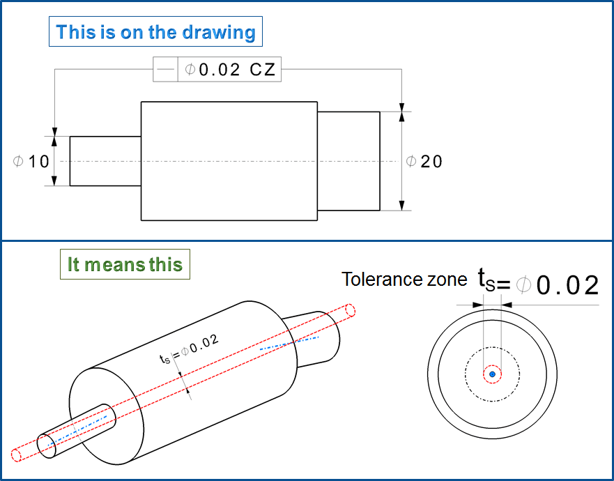
Very often it is necessary to define the “alignment” or “coaxiality” of shaft sections (or just as of holes) relative to one another, e.g. of 2 bearing seats. The simplest tolerance in this case is the entry of a straightness tolerance with a circular cylindrical “common tolerance zone” .Therefore from the tolerance control frame 2 (or more) tolerance arrows must be added, each being associated with the corresponding feature dimension. The tolerance arrow must never be on the axis itself. We cannot simply talk about “the axis” of a shaft that consists of several geometric elements, but we have to define from which elements this axis is to be derived. The specification of a common tolerance zone (“CZ” in the tolerance frame) is absolutely necessary, because otherwise the straightness tolerance would only apply to the individual shaft sections without common alignment. (Note: Something similar can also be achieved with a coaxiality tolerance)
d) Center line of a thin profile
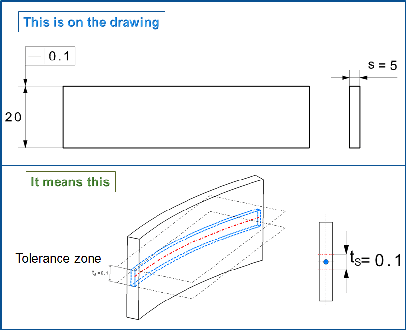
This information is only useful for relatively thin profiles, i.e. those whose thickness s is small compared to their length. Therefore in this case we can speak of a center line. A lateral bending of the strip is not restricted here.
e) Center line of a profile bar
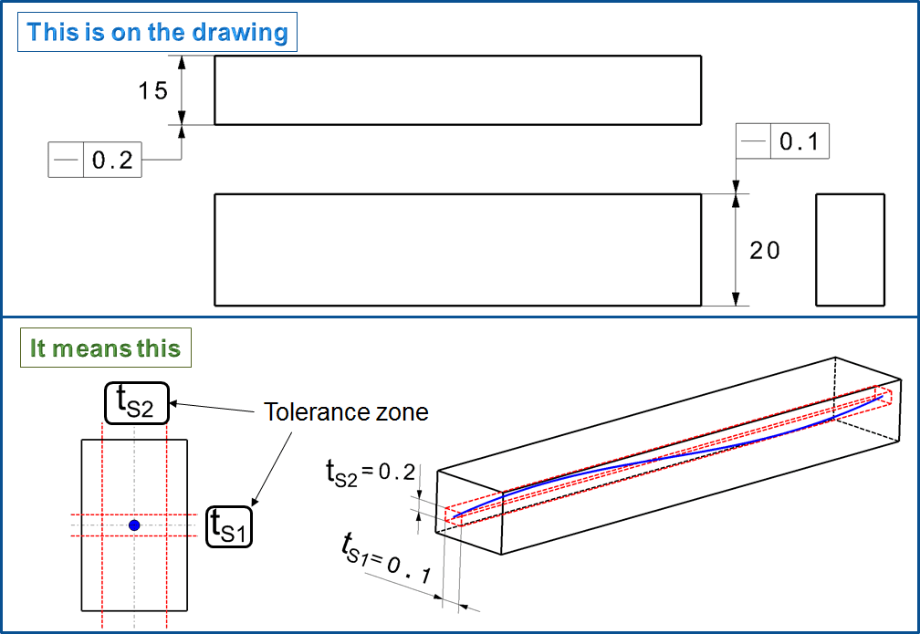
If we want -unlike with example d (Fig. 16) – to define the straightness of an axis in 2 directions, then we can indicate 2 straightness tolerances in the corresponding views. They can also have different sizes, for example to take into account different form distortions. The result being a Tolerance Zone in the form of a “rectangular tube”. In practice, the straightness is checked separately in both coordinate directions therefore for this reason a tubular tolerance zone is therefore not useful here. This tolerance is also suitable, the same like for d (Fig.16), only for slim profiles (Note: At example d and e if necessary we should indicate a reference as shown in Fig. 7)
From these examples of Straightness of derived line elements we can easily conclude that:
Straightness tolerancing of axis = When the axis of the circular elements (those elements having a complete or predominantly a circular cross-section) sould be straight, then the straightness tolerance must apply all around (in all directions) and therefore the Tolerance Zone must be tubular (having the Ø-symbol before the tolerance value). The reverse applies too: With a tubular Tolerance Zone, we can exclusively tolerate the axis.
Gauging/Measurement
Surface
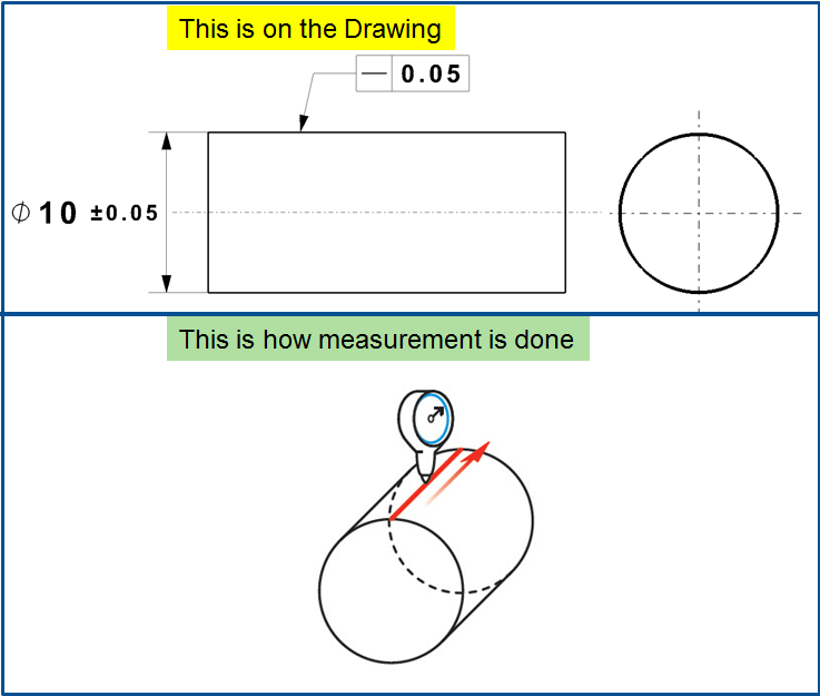
A part is constrained and a gauge measures along a straight line. In this example, the height variance is measured to see how flat or straight the line is along this surface.
Axis
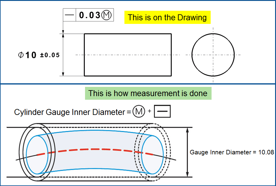
To gauge axis straightness effectively, MMC is commonly called out. To ensure that a part or feature is axially straight, a cylinder gauge is used to determine if the part fits in its total envelope at MMC. This is both a control of the diameter and of the axial straightness. The Inner Diameter of the cylinder gauge represents the maximum virtual condition of the part.
See the 2nd Example below for how axis straightness is used with a maximum material callout.
To quickly check for this, a gauge was made to check that the pin always fits into the hole in the maximum material condition. Using the calculation below the ID of the cylinder gauge can be determined to check for this during production.
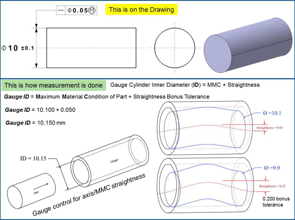
If the part is close to MMC, it has to be a tighter straightness tolerance than if it was smaller and closer to the least material condition. As long as the entire part envelope fits within the 10.15 cylinder, the part is in specification. This extra tolerance on the straightness is the bonus tolerance.
Note on Bonus Tolerance: When a functional gauge is used to measure axis straightness, the straightness tolerance can have bonus tolerance added when the part diameter is smaller than MMC. The goal of a maximum material condition callout is to ensure that when the part is in its worst tolerances, both straightness and dimensionally, that the part will always fit a given size hole. This means that if you make a part smaller in Outer Diameter, you gain bonus tolerance and can actually have it be less straight! Remember – the goal of this callout is functional: The part must fit in a specific envelope.
Bonus Tolerance = difference between MMC and the actual size of the part.
Relation to other GD & T Symbols
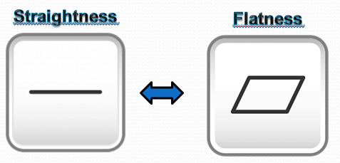
For Surface Line: Straightness can be considered the 2-Dimensional version of Flatness as both are measured without a datum and controls and refine the size of the feature. While flatness measures the variance across a 2D plane, Straightness only measures the variance on a straight line.
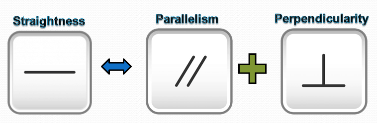
For Axis: Straightness is also closely related to axis Parallelism and axis Perpendicularity and since they both are controlling a center axis with a cylindrical tolerance zone. When MMC is applied, all of these callouts constrain the central axis to a specific variance amount ensuring the even at the worst-case tolerances, the part will function properly.
Final Notes:
Straightness and Perpendicularity with maximum material condition are most commonly used when controlling the form of a pin – while straightness controls the curve or bend of the center axis, perpendicularity controls the angle at which the pin is to a datum. Both constrain the axis of a pin feature and used gauges to control the entire feature’s boundary.

Leave a comment