
In mechanical design of things, any object is defined by 2 geometrical forms: the straight line and the circle. A combination between the 2, results in complex surfaces. Therefore we can clearly say that next to the straight line, the circle is the second basic geometrical form in the entire technique. Maintaining the circularity (roundness) of a circular or cylindrical element is therefore of elementary importance. In this post I´m gonna explain how it works.
Description
Circularity is a geometrical condition of a circumferential surface, sometimes called roundness, circularity is a 2-Dimensional tolerance that controls the overall form of a circle ensuring it is not too oblong, square, or out of round. Circularity is independent of any datum feature and is always less than the diameter dimensional tolerance of the part. Circularity essentially makes a cross-section of a cylindrical or round feature and determines if the circle formed in that cross-section is round.
A circularity tolerance controls a feature’s circularity (roundness) at individual cross sections. Thus, a circularity tolerance may be applied to any type of feature having uniformly circular cross sections, including spheres, cylinders, revolutes (such as cones), tori (doughnut shapes), and bent rod and tubular shapes.
Symbol: The symbol of circularity tolerance is the circle (as shown in figure 1.) This symbol is specified in the left compartment of the feature control frame and it is used to describe how close an object should be to a true circle.

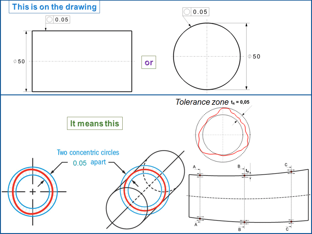
The Circularity tolerance of a machined part specifies where all points on the surface (circumference) of that circular part must lie in the zone bounded by two concentric circles which radii differ by the tolerance value of the circularity.
The tolerance call out: The tolerance arrow is always perpendicular to the tolerated geometrical element or on the tolerance zone. Therefore, on the drawing, the circularity tolerance can be called out either in the side view or in the front view.
The circular form itself says nothing about the position of the center or the dependency of one axis. The circle can be an outer element (shaft – Fig 2- A), or an inner element (hole – Fig. 2-B). Because the circularity tolerance only defines the radial distance tR between the two boundary circles, but not theirs diameter, you can also use cones – Fig 2 C) and other rotational shapes with a circular cross-section (sphere – Fig. 2- D), as shown in Figure 2.
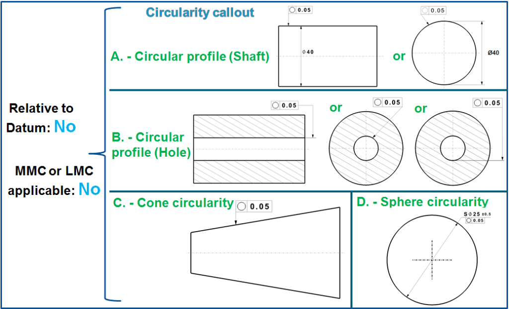
Regarding the cones, contrary to the rule, the tolerance arrow does not appear as standing vertically on the tolerated element, but appearances are deceptive. The sloping surface line has nothing to do with the circularity tolerance. The tolerance zone is a circular ring perpendicular to the axis; The tolerance arrow is perpendicular to this (in the same way like applied for shaft or hole – Figure 2 – A and B). With other words, the arrow symbolizes the scanning direction.
Figure 3. shows some senseless or incorrect circularity entries.
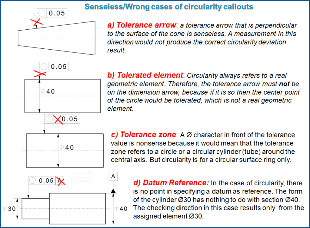
Cases from b) to d) also apply to the cylindricity tolerance.
Tolerance Zone
The circularity tolerance zone is made of 2 concentric circles, one inner and one outer, in which all the points within the circular surface must fall into. The tolerance zone lies on a plane that is perpendicular to the central axis of the circular feature.
As a Note: ASME Y14.5’s explanation refers to an “axis,” which could be interpreted as precluding curvature of the spine. Either way, most measuring equipment can only inspect circularity relative to a straight line.
Neither the diameter nor the (common) center point of the circles are set; rather, they are based on the minimum condition according to the circular contour to be checked.
If a circularity tolerance is entered for a circular cylindrical geometry element, then it applies to any cross-section individually. It therefore restricts for example either the straightness of the surface lines or a conical form of the cylinder along the axis, (fig, 2- C) For longer parts, the circularity must be measures in a reasonable number of cross-sections to be sure that the tolerance is respected everywhere.
WHEN is the Circularity tolerance is used?
Circularity is a very common measurement and is used in all forms of manufacturing. Any time a part needs to be perfectly round such as a rotating shaft, or a bearing, circularity is usually called out. You will see this GD&T symbol very often on mechanical engineering drawings.
Circularity deviations: They are mostly caused by the machine tool. Typical, idealized deviations are shown in Figure 5.
A circularity tolerance greater than the total size tolerance has no effect. A circularity tolerance between the full size tolerance and one-half the size tolerance limits only single-lobed (such as D-shaped and egg-shaped) deviations. A circularity tolerance must be less than half the size tolerance to limit multi-lobed (such as elliptical and tri-lobed) deviations.
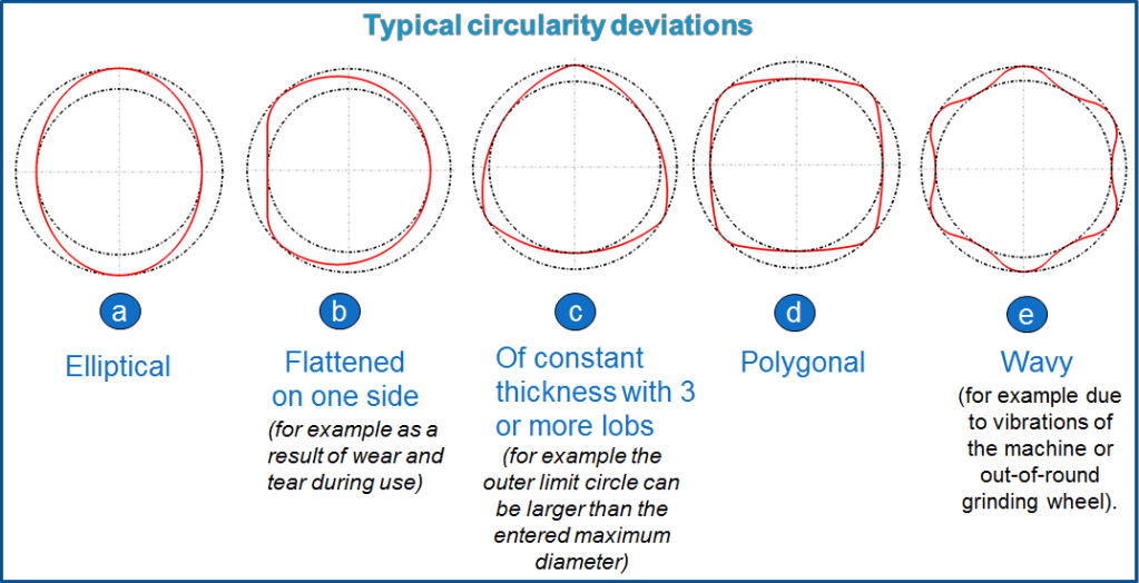
If Figure 5 shows actual profiles, then their circularity deviation is the distance between the dashed circles. The most unpleasant circularity deviation is often the one with constant thickness with 3 or more lobs (such as Fig. 5-c).
Example 1 = Circularity measurement on average diameter
If a circular feature must be controlled in its free state having an average diameter, then multiple diameter values must be measured between 2 points on different positions in the same section plane and the final result is calculated as an average value of all the measurements. (as shown in Fig. 6)
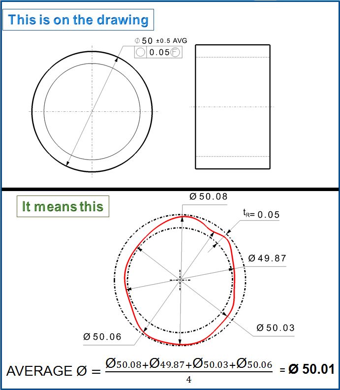
The thin-wall nylon bushing shown in Fig. 6 is typical of a nonrigid part having diameters that fit rather closely with other parts in assembly. If customary diameter size limits were specified, no matter how liberal, their inherent circularity control would be overly restrictive for the bushing in its free state (unassembled). The part’s diameters in the free state cannot and need not stay as round as they’ll be once restrained in assembly. We need a different way to control size-in-assembly, while at the same time guarding against
collapsed or grotesquely out-of-round bushings that might require excessive assembly force or jam in automated assembly equipment.
The solution is to specify limits for the feature’s average diameter along with a generous circularity tolerance. Where a diameter tolerance is followed by the note AVG, the size limit boundaries do not apply. Instead, the tolerance specifies limits for the feature’s average diameter. Average diameter is defined somewhat nebulously as the average of at least four two-point diameter measurements. A contact-type gage may deflect the part, yielding an unacceptable measurement. Where practicable, average diameter may be found by dividing a peripheral tape measurement by π. When the part is restrained in assembly, its effective mating diameter should correspond closely to its average diameter in the free state.
Though as I mentioned our nylon bushing is a nonrigid part, the drawing itself (Fig. 6) gives no indication of the part’s rigidity. In particular, there’s no mention of restraint for verification. Therefore, according to Fundamental Rule, a drawing user shall interpret all dimensions and tolerances, including the circularity tolerance, as applying in the free state. The standard implies average diameter can only be used in conjunction with the “free state” symbol (F). For that reason only, I’ve added the “free state” symbol after the circularity tolerance value. A feature’s conformance to both tolerances shall be evaluated in the free state—that is, with no external forces applied to affect its
size or form.
The same method may be applied to a longer nonrigid cylindrical feature, such as a short length of vinyl tubing. Simply specify a relatively liberal cylindricity tolerance modified to “free state,” along with limits for the tube’s average diameter.
Example 2-A = Circularity tolerance applied to a Non-spherical feature.
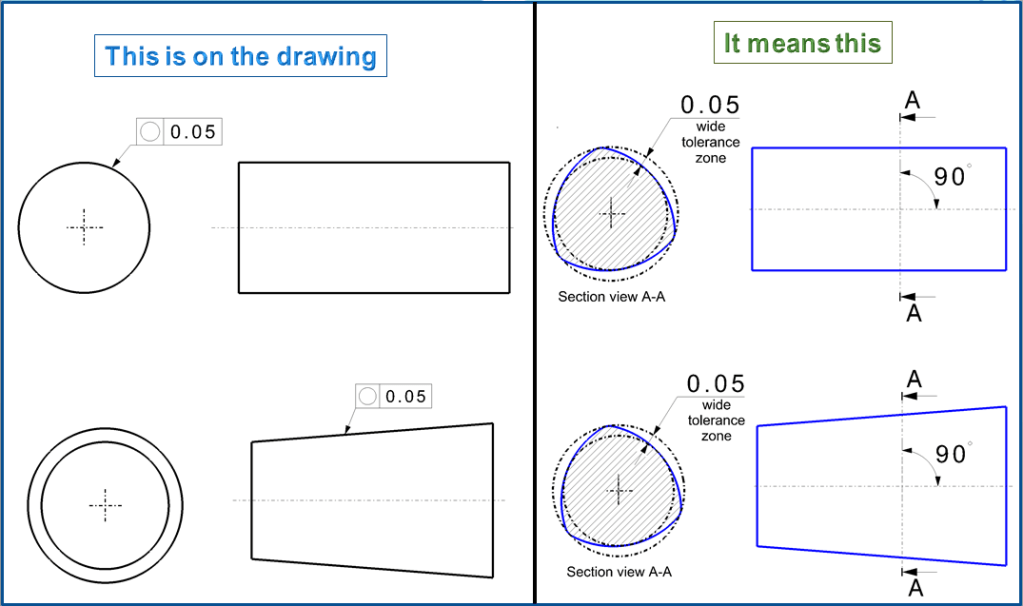
Where applied to a non-spherical feature, the tolerance specifies a tolerance zone plane containing an annular (ring-shaped) tolerance zone bounded by two concentric circles whose radii differ by an amount equal to the tolerance value. See Fig. 7.

The tolerance zone plane shall be swept along a simple, nonself-intersecting, tangent-continuous curve (spine). At each point along the spine, the tolerance zone plane shall be perpendicular to the spine and the tolerance zone centered on the spine. As the tolerance zone plane sweeps the entire feature surface, the surface’s intersection with the plane shall everywhere be contained within the annular tolerance zone (between the two circles). While sweeping, the tolerance zone may continually adjust in overall size, but shall maintain the specified radial width. This effectively removes diametral taper from circularity control. Additionally, the spine’s orientation and curvature may be adjusted within the aforementioned constraints. This effectively removes axial straightness from circularity control. The circularity tolerance zone need not be concentric with either size limit boundary.
Example 2 -B = Circularity tolerance applied to a Non-spherical feature.
In the example from Figure 8 the specified surface must be processed with the specified tolerance zone within 0.05mm in both cases (circular profile and cone).
Tolerated geometrical element: A circularity tolerance only refers to a real circle or circular cross-section perpendicular to the axis of the assigned geometry element (see ISO 12 181). (A single exception may be the circularity of the center line of a thin ring.)
Note: Cones have their own tolerance systems, the are not dealt with here; for ref. see DIN ISO 3040 and DIN 7178; Cone tolerance goes with surface profile tolerances about I will talk in another post).
Example 3 = The circularity measurement without and with circularity symbol specified on the drawing.
If you had a hole that was around a rotating shaft, Both pieces should be circular and have a tight tolerance. Without circularity, the diameter of the hole and shaft would have to be very tight and more expensive to make.

Why isn´t the circularity 0.08 to replace ±0.08 of size tolerance? – You may be thinking, well hang on – if it is ± 0.08 and circularity is the radial distance between the two circles, wouldn’t that mean the circularity should be only 0.08 since it would be on both sides? No – and this is because of how the 2-point measurement of any feature would work when compared to the smallest size vs the biggest size it could be. In GD&T there is a rule that states you need perfect form at the MMC size – meaning at the largest size for a pin (smallest for a hole), your shape of this round feature cannot let it outside of a size of 10.08 for the first example.
Example 4 = Circularity tolerance applied to a Spherical feature.
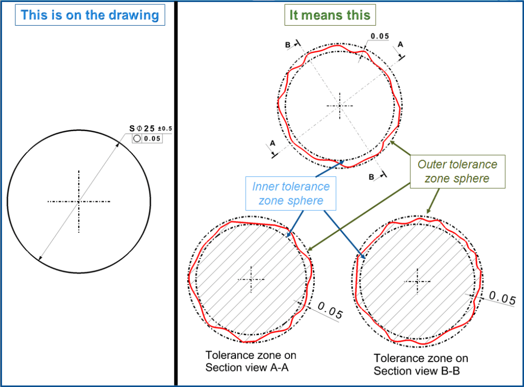
The standards also use a tolerance zone plane to explain a circularity tolerance applied to a spherical feature. Since any pair of surface points can be included in such a plane, their respective distances from a common center shall not differ by more than the circularity tolerance. Therefore, the explanation can be simplified as follows: The tolerance specifies a tolerance zone bounded by two concentric spheres whose radii differ by an amount equal to the tolerance value.
The tolerance zone may adjust in overall size, but shall maintain the specified radial width. All points on the considered spherical feature shall be contained within the tolerance zone (between the two spheres). See Fig. 10. Since the tolerance zone need not be concentric with either size limit boundary, a circularity tolerance must be less than half the size tolerance to limit multi-lobed form deviations.
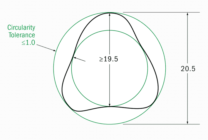
Here is a diagram showing where the surface is allowed to lie without any circularity added for a size tolerance of 20±0.5. As you can see the max size can cause the shape of the part to go to 20.5 – just like you would assume. However due to the rule in the GD&T standard – the LMC size – in this case, the smallest size tolerance, only needs to be inspected with a two-point measurement. For an odd-number lobed part – geometrically this means that the circularity is limited by the TOTAL size tolerance. So for a size tolerance of 1.0 (±0.5), your equivalent circularity control would be 1.0.
To Recap – you need to be within a perfect boundary at MMC (largest pin, smallest hole) but for the LMC (smallest pin, largest hole size) you only need to take a 2-point measurement.
Gauging/ Measurement:
Circularity is measured by constraining a part, rotating it around the central axis while a height gauge records the variation of the surface. The height gauge must have total variation less than the tolerance amount.
Limit deviation and test: The limit deviation is equal to the circularity tolerance (tr). A direct check of the circularity is very seldom possible, e.g. on thin cross-sections with large tolerances on the profile projector. You can – in contrast to straightness – not assume an adjacent element, meaning neither from smallest outer circle nor from the largest inner circle (inscribed circle) of the actual profile; Rather, there must be 2 concentric circles which are shifted in such a way that the included profile stays at its minimum between their radial distances;
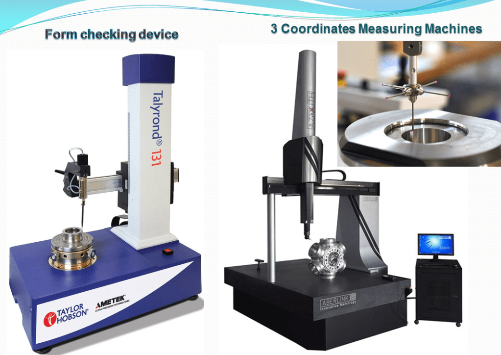
To measure the circularity in practice are used measuring devices such as form checking gauges/devices or 3-coordinates measuring devices. Form testing devices usually determine the circularity deviations via a concentric run-out measurement.
Relation to other GD & T Symbols
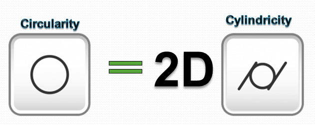
Circularity is the 2D version of Cylindricity. While cylindricity ensures all the points on a cylinder fall into a tolerance, circularity only is concerned with individual measurements around the surface in one circle. If you think of a stack of coins, circularity would be a measurement around one coin while cylindricity would have to measure the entire stack.
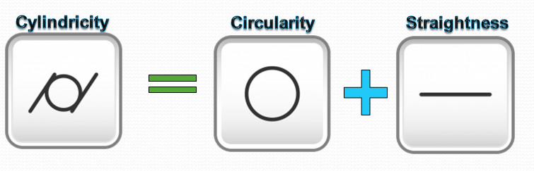
Cylindricity is actually a combination of circularity and straightness
Final Notes
Roundness – Circularity in GD&T is sometimes also referred to as Roundness. Since it is a 2-dimensional tolerance sometimes multiple sections of the same feature must be measured to ensure that the entire length of a feature is within roundness. Usually, 2 or 3 measurements are taken to ensure the part meets roundness for each segment of the part.
Statistical Tolerance Stacks: – Because circularity specifies the form of the surface in a specific area it needs to be considered when calculating a statistical tolerance stack. For example, if you have a part with a specified diameter and circularity callout, you must use both in your statistical stack since the geometric tolerance can contribute to a large part envelope than just the diameter tolerance alone. This will skew the statistical tolerance slightly higher and should be considered since parts are rarely perfectly circular.

This would be the right blog for everyone who hopes to be familiar with this topic. You already know a great deal of its practically difficult to argue together with you (not too I personally would want…HaHa). You actually put a fresh spin on the topic thats been written about for years. Great stuff, just excellent!
LikeLike
Many thanks Victor, this topic is indeed complex, almost impossible to cover all cases that occur during the mechanical product development, but at least I consider that a good understanding of the basic principles of how these things work is mandatory for anyone who does mechanical design. And sure if you have doubts, suggestions or just questions on this topic, don’t hesitate to argue with me, I am always curious to learn more :-);-)
LikeLike
Du er da godt nok hårdt ramt af spam kommentarer
LikeLike
Hi Carl, unfortunatelly I don’t speak Danish, but I do have a good level of Dutch and German so I can make some connections with Daninsh too. You’re right I receive a lot of spam comments, yet that’s detected directly by my blogging system, I didn’t make any special settings for that. However I can anytime unspam a comment if the conversation is meaningfull. As long as you don’t send me comercialls or anything else unrelated to the topics I discuss here, then you are anytime welcome to comment on my blog. 😉
LikeLike
Spot up for this write-up, I truly believe this web site wants considerably more consideration. I’ll more likely be again to study considerably more, thank you for that information.
LikeLike
Likewise, thank you for reading. I am greateful for this :-);-)
LikeLike
Merely wanted to present you a shout on the valley of the sun, great information. Much appreciated. Great post! Nice one for share.
LikeLike
Thank you very much. I appreciate this 😉
LikeLike
I’d have to talk to you here. Which isn’t something Which i do! I love to reading a post that should get people to think. Also, thank you for allowing me to comment!
LikeLike
Of course you’re welcome to comment 🙂 I am indeed selective on which comment I allow and which not, because I also receice many messages (spam) which have nothing to do with the topics I discuss here. But as long as someone’s is on the topic, then I appreciate every comments. I love to learn from other perspectives as well. Thanks a lot for reading my stuff.;-)
LikeLike
I am really inspired along with your writing skills well with the layout in your blog. Is this a paid topic or did you customize it yourself? Anyway keep up the excellent high quality writing, it’s rare to look a great weblog like this one today..
LikeLike
Thank you very much. No, it’s not paid, I just share my knowlegde in engineering based on my own experience working on product development during the years. I also have a academic background in materials science and decided a while ago to find a way to share such topics as most as possible in an inspiring and interactive way. That’s how I ended up blogging about it :-). If you wish you are anytime welcome to subscribe and follow my blog, I regularlly publish new material. And for a while I will keep doing this for free 😉
LikeLike
I would read more on this topic if the info provided were as interesting as what you have written in this article. Don’t stop caring about the content you write.
LikeLike
Of course, I do my best to deliver interesting stuff ;-). Thank you so much for reading 🙂
LikeLike
Great post. I was checking constantly this blog and I am impressed! Extremely useful info particularly the last part I care for such info a lot. I was seeking this certain info for a long time. Thank you and good luck. .Chlebek Dukana
LikeLike
I’m glad to hear. Thank you for reading 😉
LikeLike
It’s a pity you don’t have a donate button! I’d definitely donate to this excellent blog! I guess for now i’ll settle for bookmarking and adding your RSS feed to my Google account. I look forward to fresh updates and will share this website with my Facebook group. Chat soon!
LikeLike
Thank you very much. I didn’t think to add a donate button to my blog, but probably I’ll consider to add it soon, it’s a great idea ;-). Also, If you wish you can always subscribe to my blog and you’ll receive fresh updates directly into your email inbox , I often publish new stuff ;-).
LikeLike
Decidedly refreshing idea, I suppose I will give it a shot. Thanks!
LikeLike
I have to say this post was certainly informationrmative and contains useful content for enthusiastic visitors. I will definitely bookmark this website for future reference and further viewing. thank a bunch for sharing this with us!
LikeLike
yeah bookmaking this wasn’t a speculative decision great post! .
LikeLike
Great job, wonderful blog… really enjoy it and put into my social bookmarks. Keep up the good work
LikeLike
Thank you for sharing with us, I conceive this website really stands out : D.
LikeLike
😉 🙂
LikeLike
I’ve been absent for a while, but now I remember why I used to love this web site. Thank you, I’ll try and check back more frequently. How frequently you update your website?
LikeLike
I’m glad to hear you like my website. Thank you so much ;-). I have a lot to share, I don’t always have time to publish new stuff as often as I wish, but I try to do it regularly. I would say at least once a week I publish something new. Sometimes I do it even multiple times a week. 😉
LikeLike
I your writing style truly loving this web site .
LikeLike