
In manufacturing is often the case that parts are metalic and have a specific constant thinkness. In CAD of course no problem to design such a part but the work is much faster and effective is you don’t design these parts using the standard way of doing it as Solid component but instead you do it as SheetMetal part.
Sheetmetal design is possible with all major CAD platforms. In this post I want to show you how does it work with CREO Parametric.
STEP 1.

Create an New Part with the Sub-Type as Sheetmetal
STEP 2.
Start by defining the base plate as an “Extrude” feature on which you will add the rest of the Sheetmetal design features. Click on the “Extrude” icon
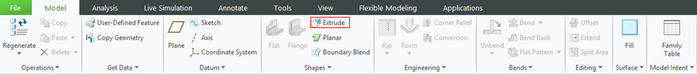
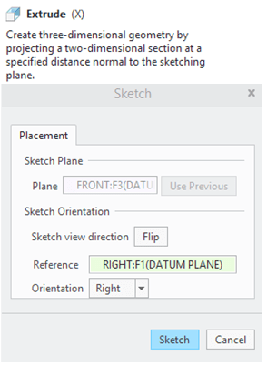
Choose the sketching plane and click on Sketch button
Draw a horizontal line as shown:
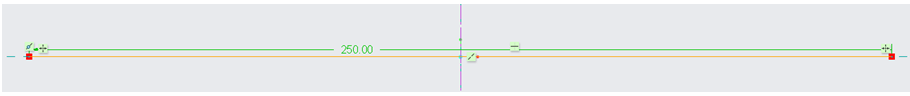
Do the necessary settings in the Extrude dialog box as shown and click OK.

STEP 3.
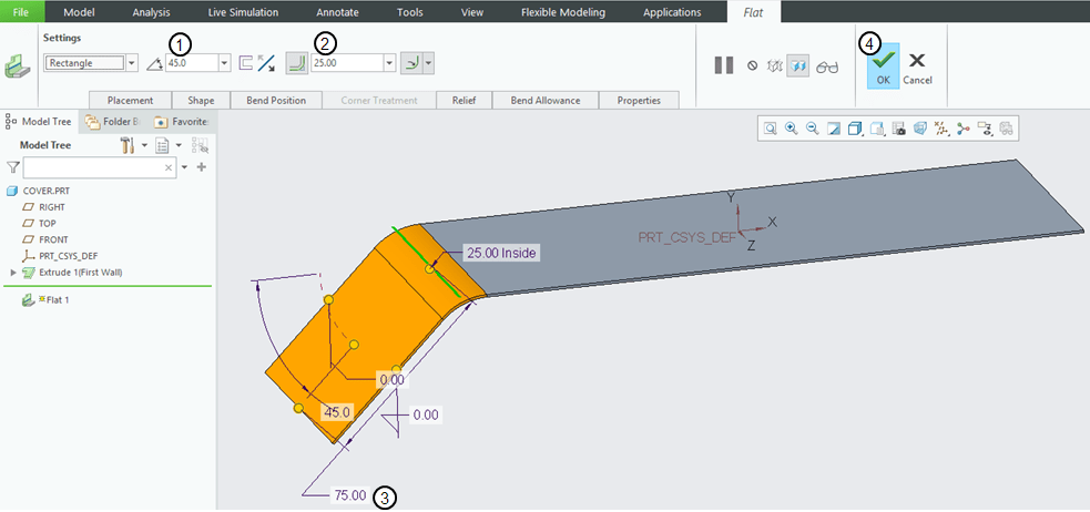
On the previously created feature you can add now the other sheetmetal elements. The first feature is a Flat wall.


Click on the ouside Edge as shown to add the next Flat wall.
Do the necessary parameter settings and click OK.
STEP 4.
Do it again for another Flat wall as shown:
STEP 5.
In the Model Tree keep the previously 2 Flat Walls selected and mirror them versus the middle plane.

STEP 6.
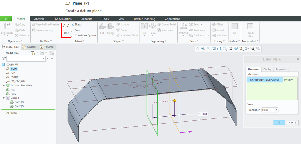
Create an additional datum plane with an offset of 50mm from the Middle plane
STEP 7.
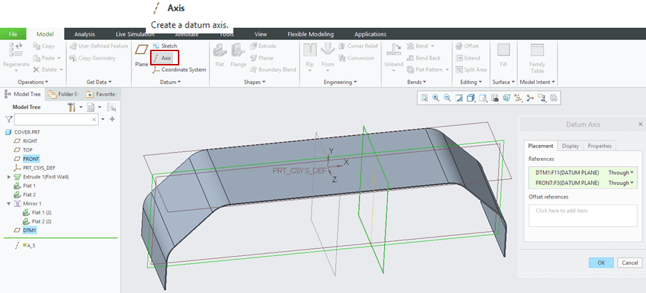
In the working view select both the Datum plane you’ve previously created and the Front plane and click the “Axis” icon in order to create an axis at the intersection of these 2 planes:
STEP 8.
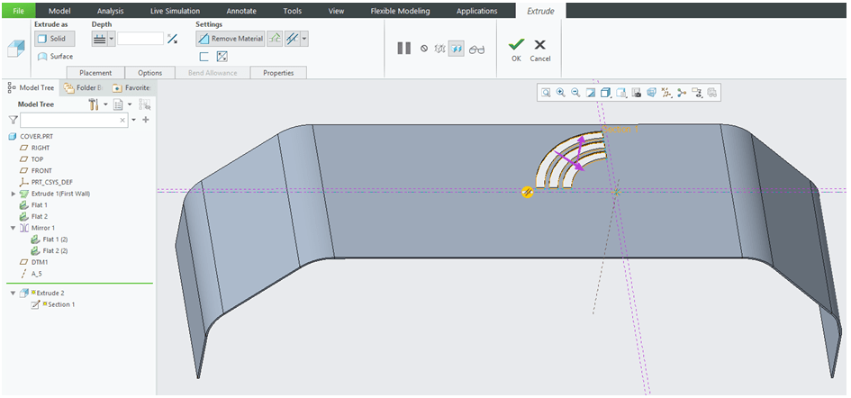
Create a cut-out on the front surface of the cover. To do that CREO Sheetmetal workbench click on the “Extrude” icon –> Select the front surface as Sketching reference…
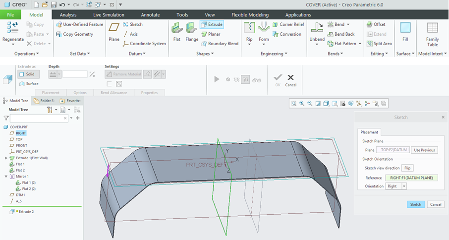
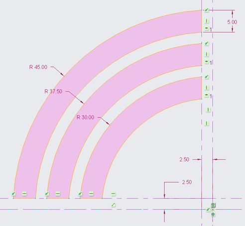
… and draw the sketch as shown.
In the Extrude dialog box check if the cut-out is correctly done and if so click OK to create it.
STEP 9.
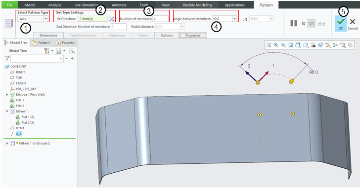
Pattern the cut-out around the previously created axis with the following parameters:
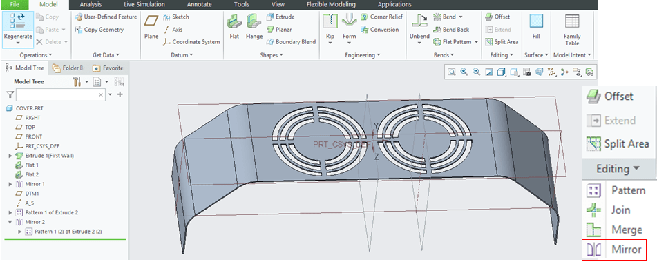
In the Model Tree keep the last feature as ” Pattern 1 of Extrude 2″ selected

STEP 10.
…. and mirror it versus the middle plane.
STEP 11.
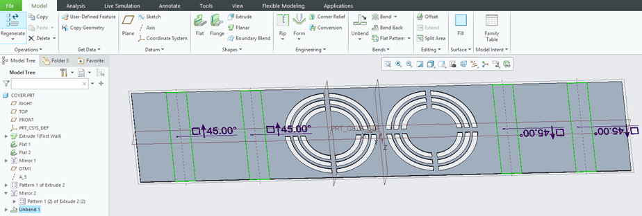
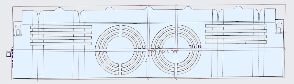
Now Unbend the current design.
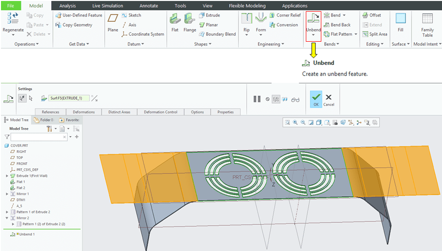
Confirm this by clicking OK; The flat design looks like this:
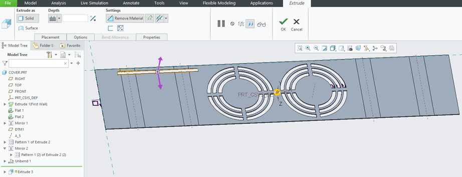
STEP 12.

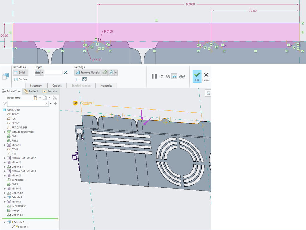
In the Creo Sheetmetal workbench, Click on “Extrude” icon and select the unbended surface as sketch reference, draw the sketch as shown.
Confirm this with a click in OK in the Extrude dialog box.
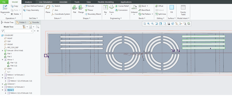
STEP 13.
Pattern the previously created cut-out allong the direction Z as shown

STEP 14.
In the Model Tree keep the last feature selected and mirror it versus the middle plane
STEP 15.
Bend back the current design
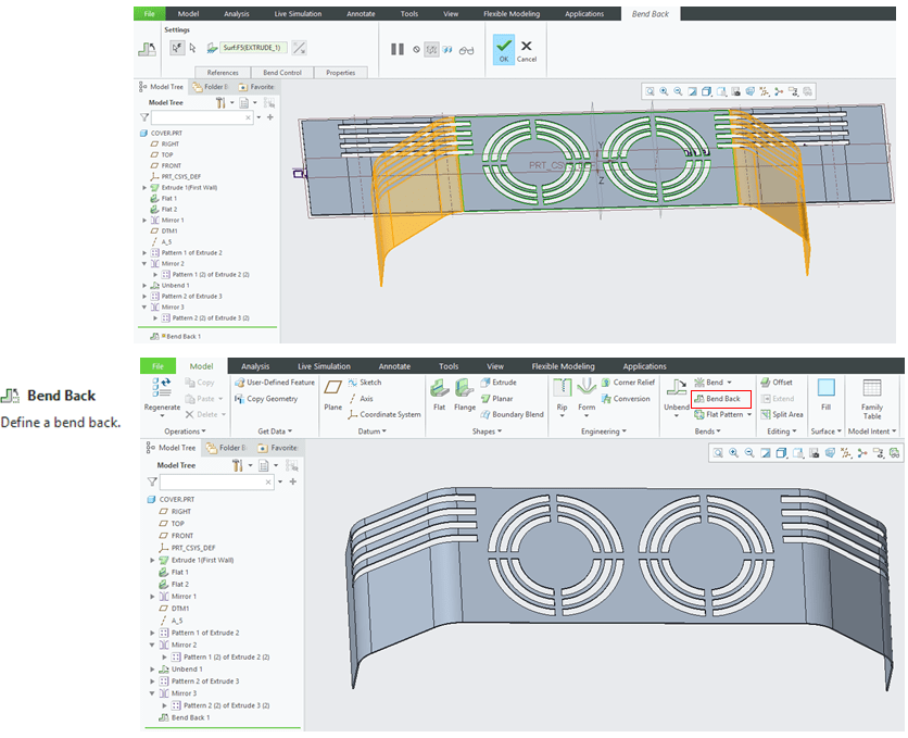
STEP 16.
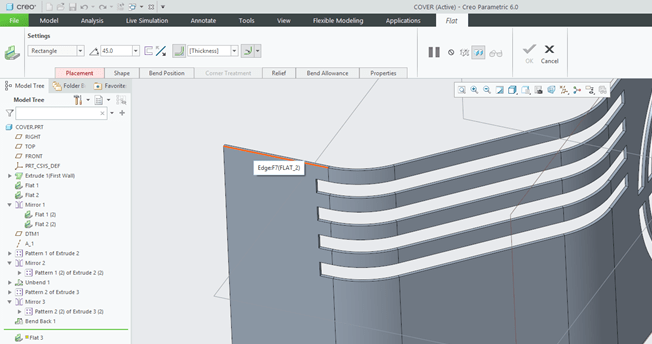
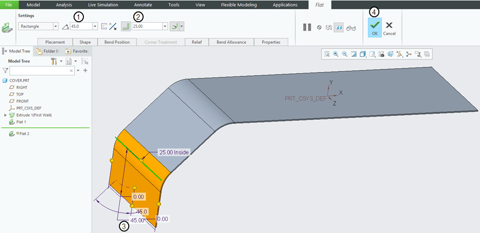
In Creo Sheetmetal workbench click on “Flat” icon to add a new Flat wall on the edge as shown
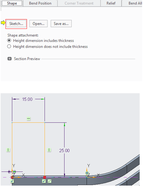
But this time the Flat wall must have a specific shape. So on the “Shape” tab keep the default Shape attachement setting, click on the “Sketch… button and modify the sketch as shown
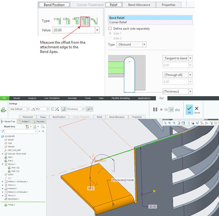
Back in the Flat wall dialog window do the settings for the “Bent Position” and “Relief” and click OK to generate the new feature.
STEP 17.
Mirror the Flat 3 with the middle plane
STEP 18.
Unbend again the part
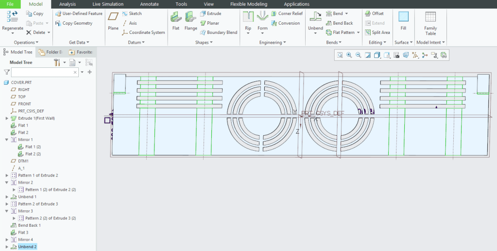
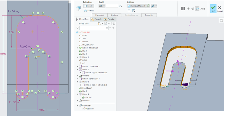
STEP 19.
Select the unbended surface as sketch reference and draw the following sketch:
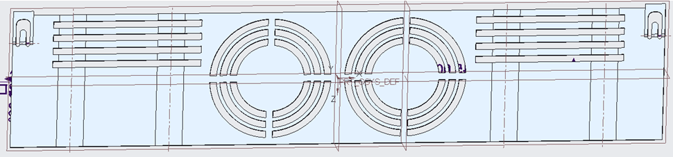
STEP 20.
Then Mirror the just created cut-out with the middle plane
STEP 21.
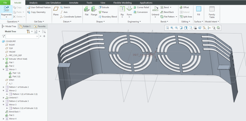
Bend back the part.
STEP 22.
On the upper side of the Cover part create the next feature called “Flange”. To have a continuous flange on the entire upper edge, select each segment by holding the SHIFT key down while left click untill all necessary edges are picked. Keep the settings for “Mitter Cuts” as shown.

STEP 23.
Unbend the current desing.
STEP 24.
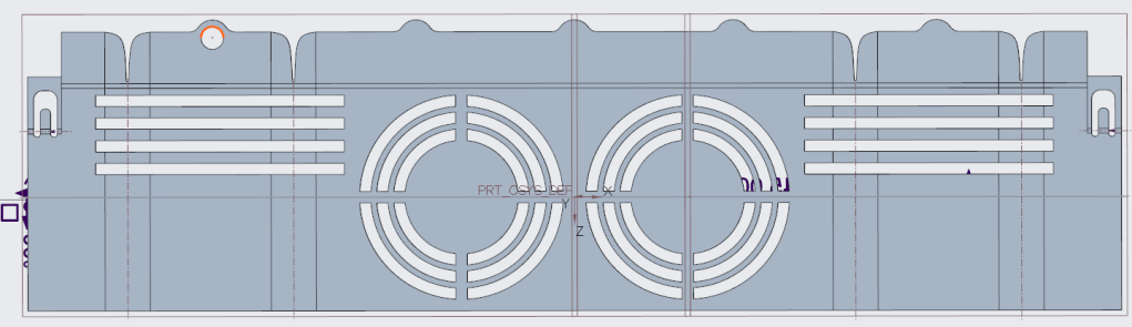
Cut the upper side with a sketch as shown. Create this only for the left half.
STEP 25.
And now mirror this cut with the middle plane.
STEP 26.
Futher on you will put some holes and pattern them via Table reference; But before that you need to create an additional Datum axis.
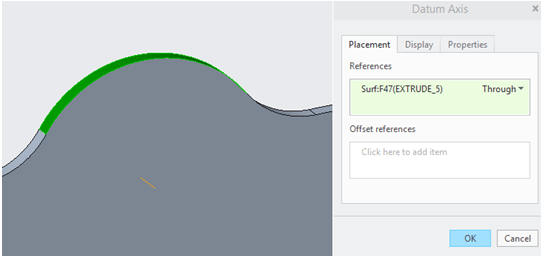
In the Creo Sheetmetal workbench click o on the “Axis” icon and create it as shown.
STEP 27.

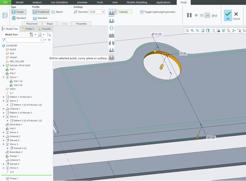
Now you can create the holes. Actually you need to create only one hole which must me liniarly dimensiones because you will multiply it via a table pattern.Click on the “Hole” icon:
… and pick the flat outer surface in order to linearly position the hole as shown:
STEP 28.
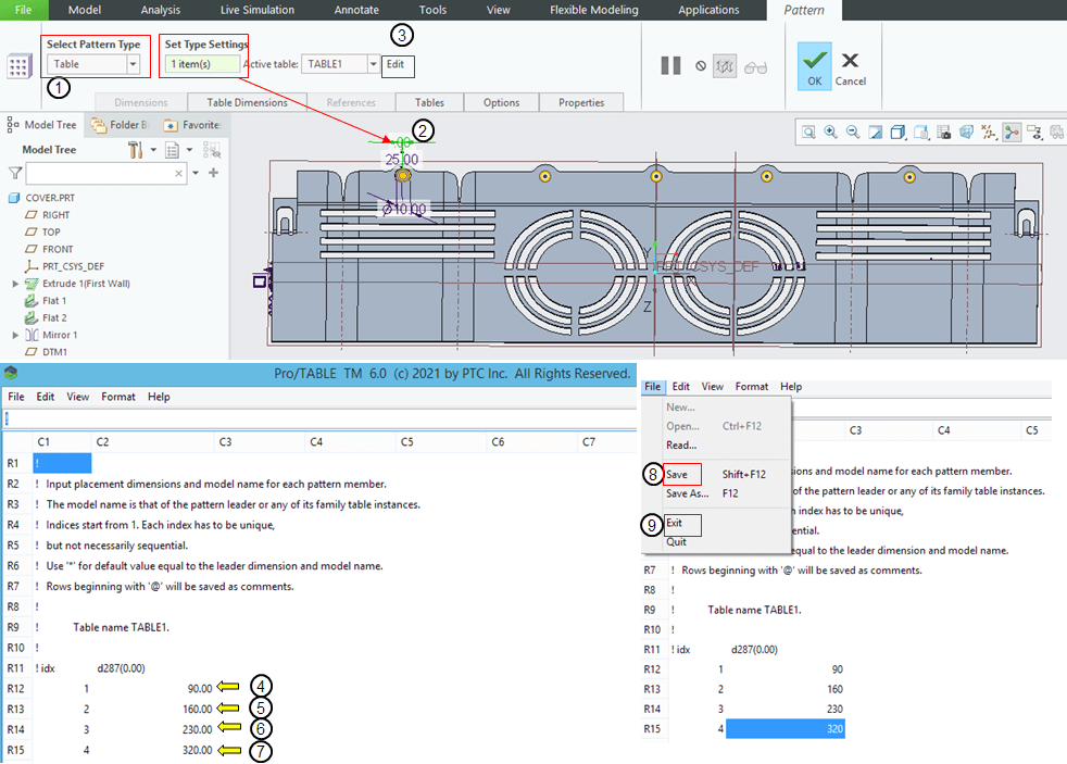
Pattern the hole using the Table type pattern with the parameters as shown below. To create the table you must in the “Set Type Settings” box you must have one item which is the hole position related to the construction axis. Because it is the first hole this value is the 0.0 mm all the other holes will be positioned at different distances from this reference; so click the value 0.0 to add it as selected item and follow the setting steps as showed:
STEP 29.
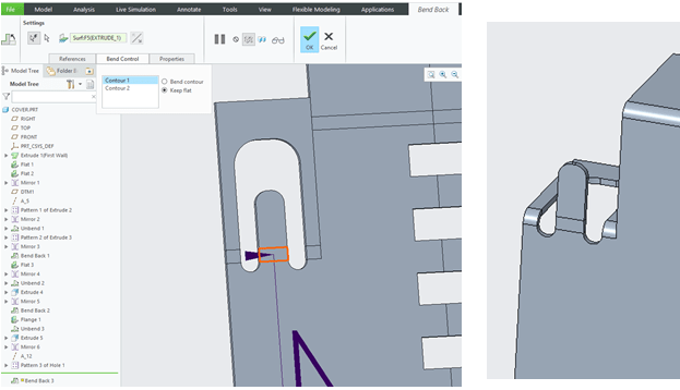
Once the holes are added “Bend back” the part and keep the small inner latches on left and right unbend.
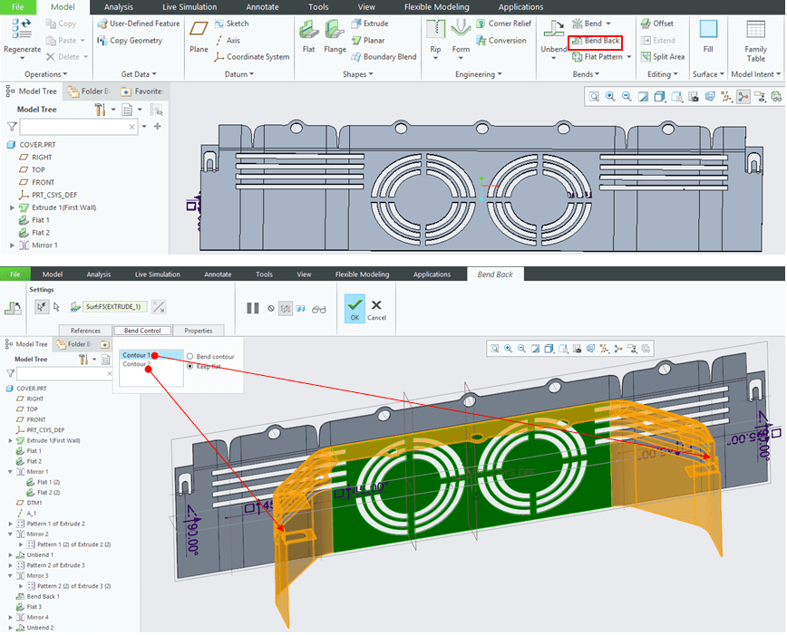
You can easily control the bends via “Bend Control” tab where you have the option to bend the contours or to keep them flat.
STEP 30.
Next feature you will add is the “Flange” for every hole on the upper side wall. Click the “Flange” icon and with SHIFT key down selet the inner edges of the hole, put the height at 3mm and click OK.
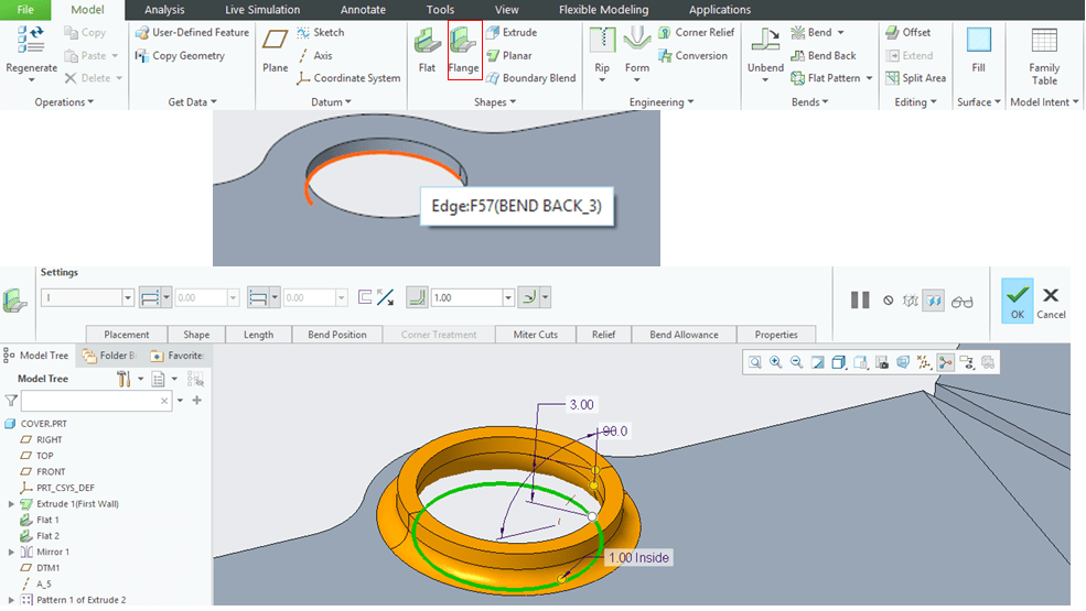
Do the same for all the holes.
STEP 31.
In the next steps you will add beads to your sheetmetal design. For that you must add a coordinate system and create a separate Punch parst which will create the Beads on your Sheetmetal cover.
First you must create an additional coordinate system. To define that you also need 2 additional datum planes.
In the CREO Sheetmetal workbench click on the “Plane” icon and select the bottom surface of your sheet metal edge and offset the plane inwards with 35mm. Then create a second plane with 85mm offset from the side

STEP 32.

Select the 2 additional planes and the top surface of the sheetmetal part and click “Coordinate System” icon. Creo will automatically creat the new datum.
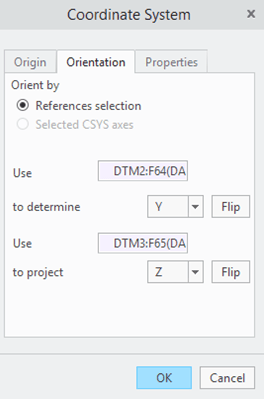
In the “Orientation” tab you have the option to orient the coordinate system as you wish.
STEP 33.
Now you can continue with Bead creation.
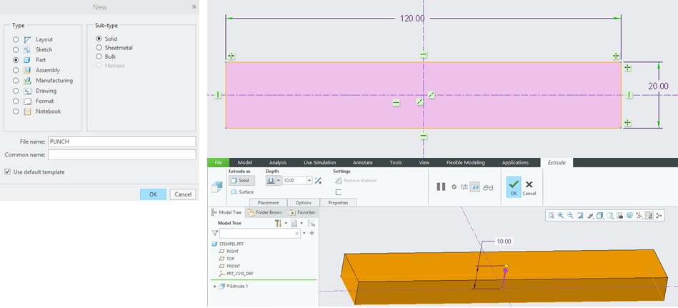
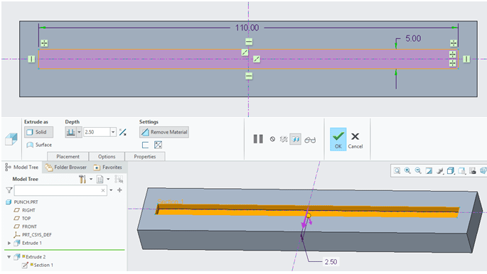
For this you must create a new part which will be the punch that will add beads to your sheetmetal design. So click “New” icon and create a solid part.
As you have previously already created a new Coordinate system on your sheet metal make sure the Punch part will have its own coordinate system with exactly the same orientation like the one you put on the Sheetmetal, otherwise you might have difficulties to create the beads. Therefore create the Punch part as suggested below.
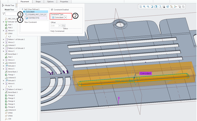
STEP 34.
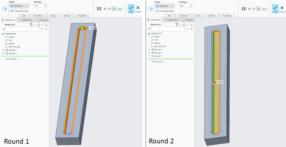
Now you can add the last features on your sheetmetal design using the “Die Form” to generate the beads.
Click on “Die Form” icon and CREO will ask you to point the which file to be used to generate the new feature. Do the setting steps as shown below:

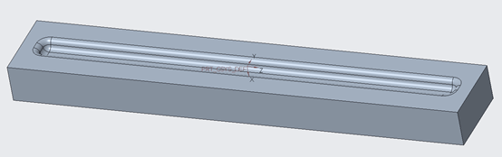
The first bead is now added on your Sheetmetal design.

STEP 35.
Pattern the created bead in the direction of the side edge with the following parameters:
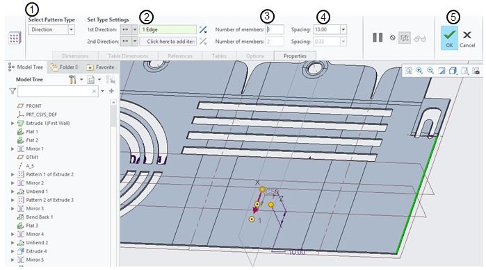
STEP 36.
Then mirror the pattern of beads with the middle plane.
STEP 37.
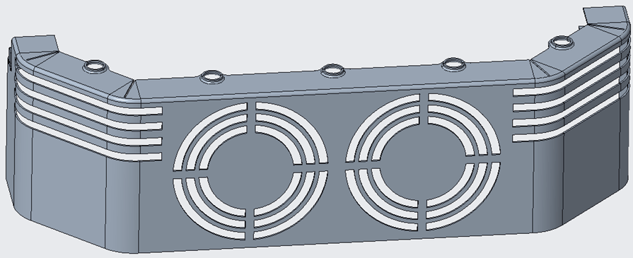
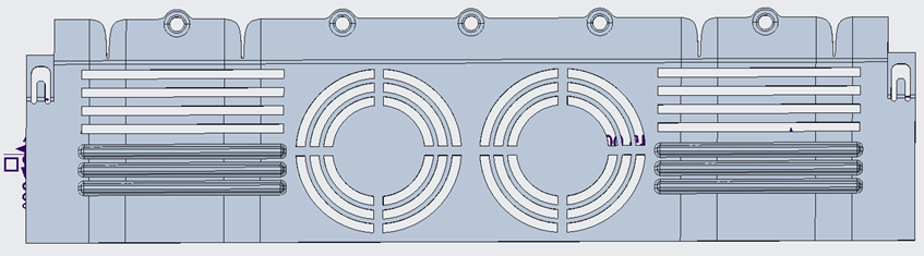
Bend back the part except the 2 little inside latches for the sides. To do this, use the Settings in manual mode and in the “References” tab remove the geometry which you don’t want to bend back.
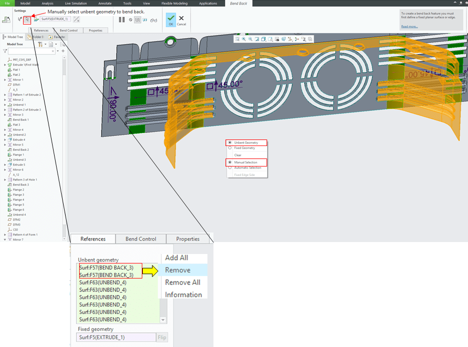
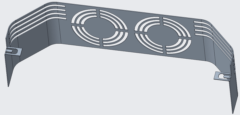
Here is the final sheetmetal design.

This exercise is also available as video version on my YouTube Channel as shown below:

Leave a comment