
Mechanical design exist for very long time. People have always created objects in different ways. Since the invention of CAD platforms mechanical design of things didn´t change the way how people imagine the objects they wish to create but these CAD platforms are today very powerful and even if it doesn´t really matter which such software you use to create a mechanical part – because at the end all want matters is the final product which must be reliable, useful and usable – the design strategy used in the design process can indeed have a big impact on the entire stage of project development. So clearly CAD platforms have a big advantage versus manual drafting.
It might be also possible that not all design strategies work well for all CAD platforms. There are of course many similarities between these software but the way how their interface work can be different. In this post I want to show you how you can design a product in Relational Design Method using CATIA V5.
Relational Design Method is a mechanical design approach in which parts are created in an assembly context, using links to a reference data model having Published elements which can be used together with parameters and formulas, in order to create and update a part or an assembly. This means that you only create the reference data model with the right published elements and use that in a new assembly where you directly create the other components parts, without individually create each part and put them later in an assembly using Assembly Constraints.
Relational Design Method can save a lot of time and is very useful to generate different design versions for the same products. The drawback is that you must be very careful how you create the links and how you save the parts afterwards. Because if by accident or mistake links are broken, it could be difficult to recover.
In this post I will show you how to design a Mouse, in a interactive work with 3 different CATIA V5 workbenches all in a RELATIONAL DESIGN Approach, these 3 workbenches are:
- Assembly Design,
- Generative Shape Design,
- Part Design.
So let´s start
REFERENCE 3D MODEL
For a Relational Design Approach the first data you need to create is the Reference Model.
STEP 1:
Create a New CAT.part with the following settings:

STEP 2:
In Part Design workbench, for a better workflow and future part updates, before to create the part features is always good to establish the right structure in the Model Tree. For this exercise I propose you to organize the Tree structure in 4 Geometrical Sets an 1 PartBody item. By default Catia provides you 1 Geometrical Set and 1 PartBody everytime when you create a new part. So in addition to that, insert 3 more Geometrical Sets and rename everything in the tree for example as shown below:

STEP 3:
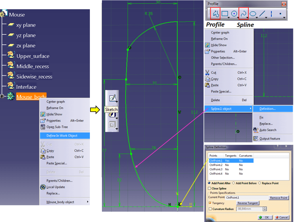
As base feature on which you´ll develop all the design work you need to create a solid block. For that, make sure the Housing item is the “In work object” (if it not, just right click on its name and from the context menu click on “Define In Work Object”) and go ahead and create the first Sketch as shown below. This Sketch can be made using 2 Profile item. First, draw the horizontal and vertical reference axis and then start drawing the rest with a click on the “Profile” icon, draw a line and a arc, put the corresponding dimensions and constraints. then continue drawing a “Spline” with 4 points. The first point of the spline must be coincident with the origin point and must have the “tangency” arrow activated so that it will make the spline perpendicular in this point with the symmetry plane. Put the rest of dimensions and constraints until the entire sketch becomes green and exit the Sketcher Workbench.
STEP 4:
Create a Pad feature using the previous sketch and give it the length of 33mm.

STEP 5:

All the time when such relational design is done, involving GSD features and PartDesign solid features, you must constantly switch between the workbenches.
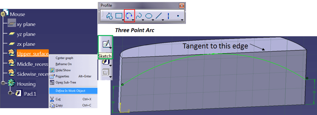
Let´s define now the upper surface. For that make sure the geometrical set named “Upper surface” is the In Work Object”, click on the symmetry plane and sketch a Three point arc as shown, 16mm height on the left and 15mm height on the right
STEP 6:

Create a reference point in the middle of the three point arc.
STEP 7:
Create 3 reference planes, normal to curves, 2 planes on the bottom edge and 1 plane normal to the Three Point Arc in the middle point.

STEP 8:
One each of the previously created planes, draw similar sketches using the “spline” icon and make it at the upper point tangent activated, as coincident and perpendicular to the symmetry plane.

STEP 9:
With the 3 sketches on the reference planes as “sections” and the sketch on the symmetry plane as “guide”, eventually use the bottom straight edge as Spine, create the “Multi-Section Surface” as shown.

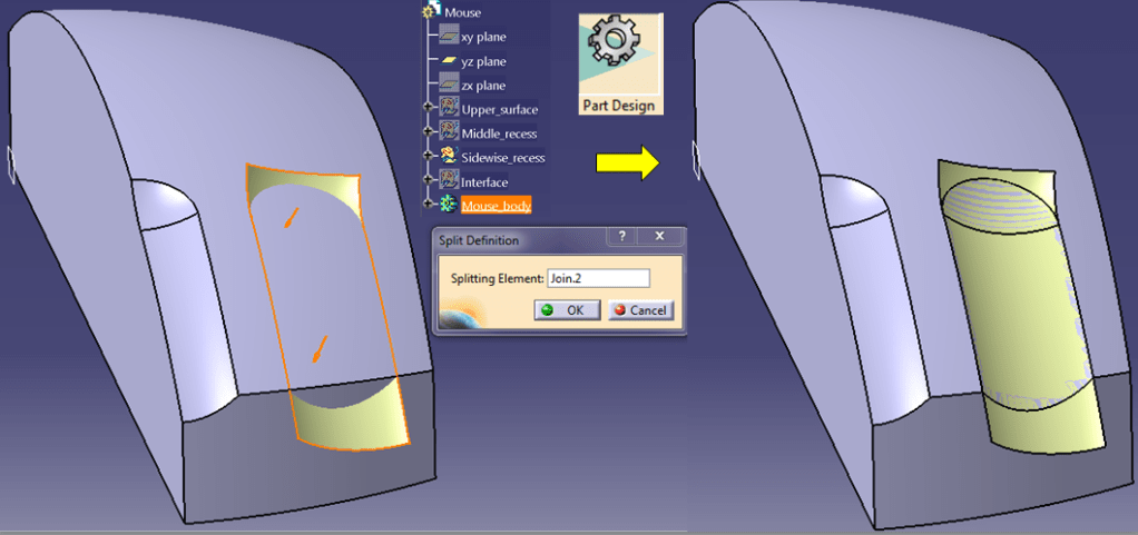
STEP 10:
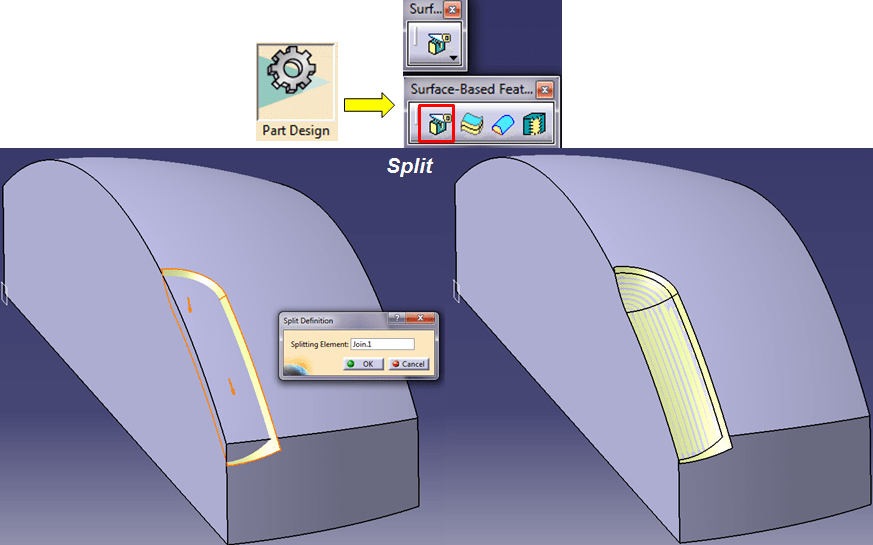
Switch to “Part Design” workbench, make the Mouse body as “In Work Object” and split the solid with the previously created surface.

STEP 11:
Next task is to define the middle recess are which you´ll use to desugn the middle click. In “Generative Shape Design” create 2 construction planes, one at an offset ot 6,5mm from the symmetry plane, and another one at an offset of 25mm from the top plane.

STEP 12:
With the 2 previously created planes, create an intersection with the splitting surface.

STEP 13:
Split the long intersection line with the short intersection line and on that split create a plane normal to its end point. On the resulted plane, create 2 sketches with will define the shape of the recess. Draw the Sketch I as a simple arc. making its center point and the left end point coincident with the symmetry plane. Then make the arc line coincident with the point where the sketch plane is normal to. Add a 1mm length sidewise at the other arc end point.
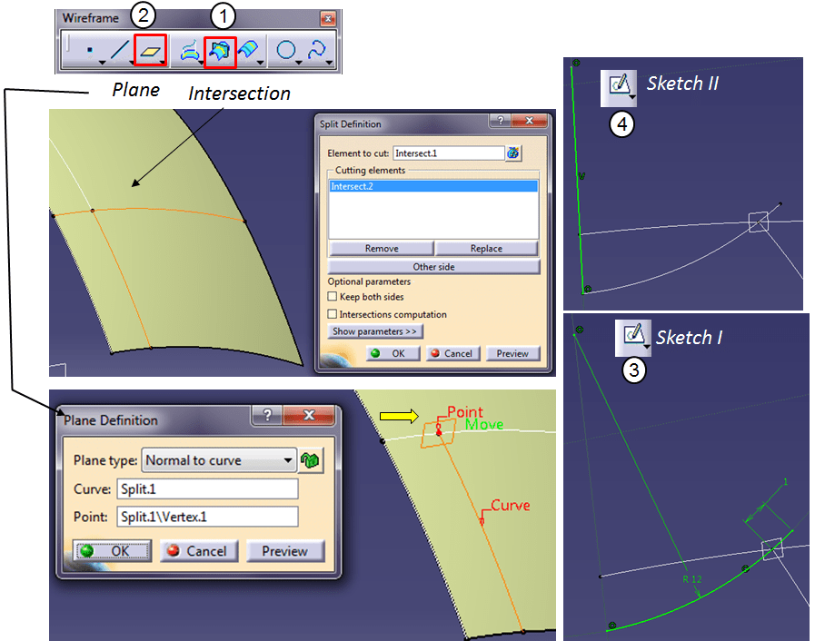
Then, create the Sketch II on the same plane, just as a vertical line coincident with the symmetry plane an the left end point of the arc created as Sketch I.
STEP 14:
Click on “Revolve” Icon, select Sketch II as rotation axis and Sketch I as Profile. Put 0° for Angle 1 and 90° for Angle 2, and click OK. Then create a sweep along the Split 1 using the same Sketch I as profile. Extrapolate the resulted Sweep with 2mm and Join the result in continuity and tangency with with the revolved surface.

STEP 15:
Switch to Part Design workbench and split the existing solid with the previously created surface/join.
STEP 16:
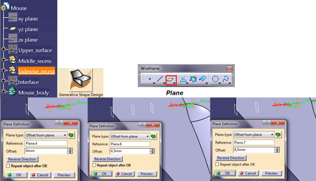
Next task, is to define the sidewise recess, which will define the left & right click button of your designed part. Go back to GSD workbench and make sure the “Sidewide recess” geometrical set is “In Work Object”. Create 3 more construction planes starting with an offset of 6mm from the plane that defines the middle recess. put the other 2 planes at 6,5mm from each other.
STEP 17:
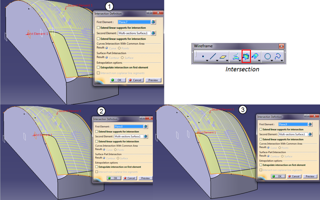
With each of the 3 reference planes previously created, generate an intersection with the upper surface.
STEP 18:
Cut the middle intersection in the same way like you did for the middle recess and put a plane normal to its end point. Then cut the other 2 side intersections with this plane.

Extrapolate all the splited lines with 5mm outwards.
STEP 19:
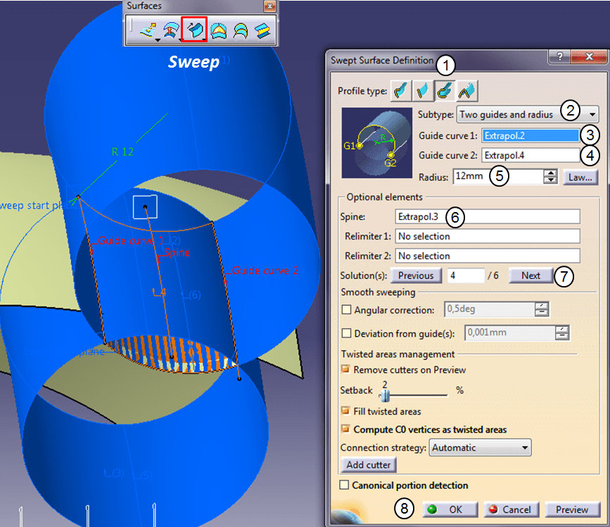
Using the 3 extrapolated lines, create an explicit Sweep with a radius of 12mm.
STEP 20:
On the plane created at STEP 18, create a construction sketch made of 2 lines (one as design line and the other as construction line) perpendicular on each other and coincident at one end point. The coincidence point of these lines must be concentric with the Sweep Edge. Exit the Sketch and create a Revolve feature using the previous sketched line as “Revolution axis”, put Angle 1 =40° and Angle 2 = 0°.
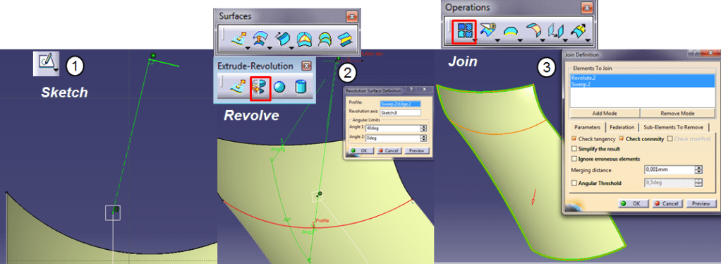
Then Join the Sweep and Revolve surfaces, in continuity and tangency.
STEP 21:
Switch to Part Design Workbench and split the existing solid with the previously created join surface
Now both middle and sidewide recess are created.
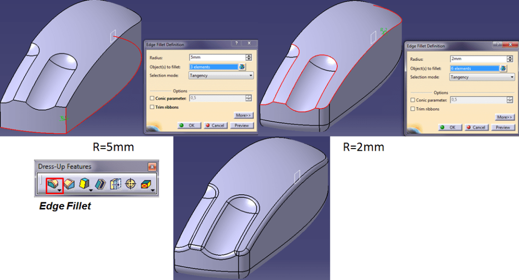
STEP 22:
Add a 5mm Edge Filles on the bottom edges and left corner and put another edge fillet of 2mm on all the other edges except those in the symmetry plane.
STEP 23:
The reference elements are fully defined. In order to use this design model in a Relational Design approach, you must create the skeleton with published features that will serve as external data to generate the other related component parts. So let´s create now the elements to be used as Published features.
Swich back to GSD workbench and make the “Interface” geometrical set as “In Work Object”. Extract the entire outer surface except the one in the Symmetry plane. The translate the Upper surface inwards with 5,5mm in XY direction using the rear vertical edge of the previous extract.

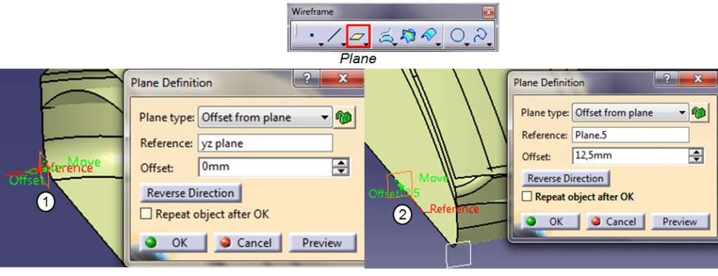
STEP 24:
Define 2 additional reference planes. One having a offset of 0mm form the initial symmetry plane defined by YZ plane. And another one with an offset of 12,5mm from the 2nd plane defined at STEP 11 for the Middle recess.
STEP 25:
And to define one last construction plane, you need to create 3 additional points before. So create a Point on the 1st plane defined at STEP 11 for the middle recess, indicate the point reference as the Origin point and put 0mm on both H and V vectors.
Then create the 2nd point in the same way using the 1nd Plane defined at STEP 16 for the sidewise recess. Using these 2 new points create the 3rd one as in “Between” type. Finally in this 3rd point add the last plane parallel through point having the reference the symmetry plane as defined at STEP 24.

STEP 26:
In the “Interface” geometrical set you have now 3 planes and 2 surfaces. These are the references you need to create the final Relational Mouse Design. So to do that, you must Publish all these 5 features.
In “Tools” Menu, click on “Publication…” and before to add anything check on the “Options…” button if the Rename the element is activated on “Always” and click OK. Then you can add all 5 elements as I´ve mentioned earlier.
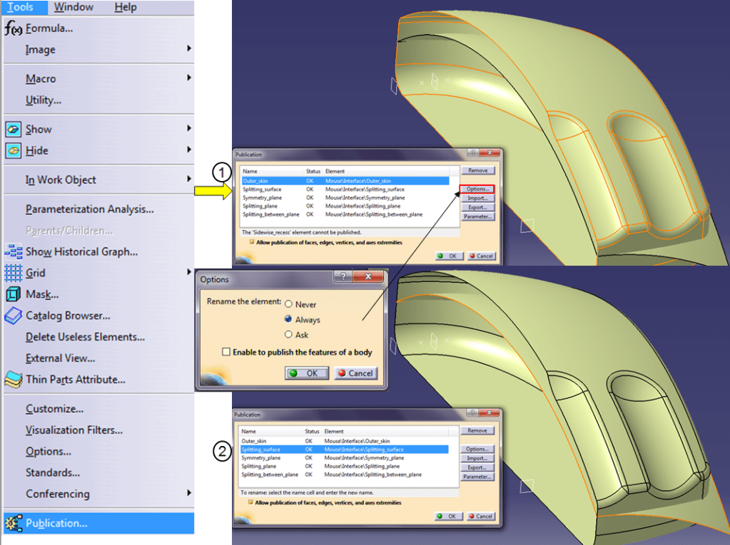
Before to close the “Publication” dialog window, click on each element and rename it as shown:

Then click OK to Publish the 5 elements. Your Reference Model is now ready to be used and it looks like this:

Save your work until now and close this part model.
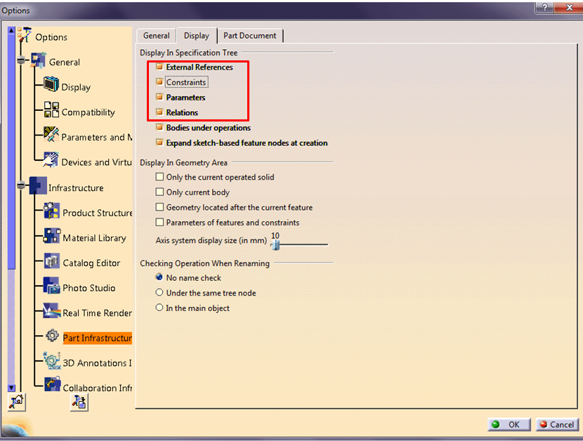
STEP 27:
Working properly with the Assembly in a Relational Design method, requires some specific settings. So before to continue make sure you have all the options selected as shown below:

ASSEMBLY DESIGN
STEP 28:
Create a “New” Product. In Assembly Design Workbench click on the “Existing Component” and add the Previously created Reference Model.

STEP 29:
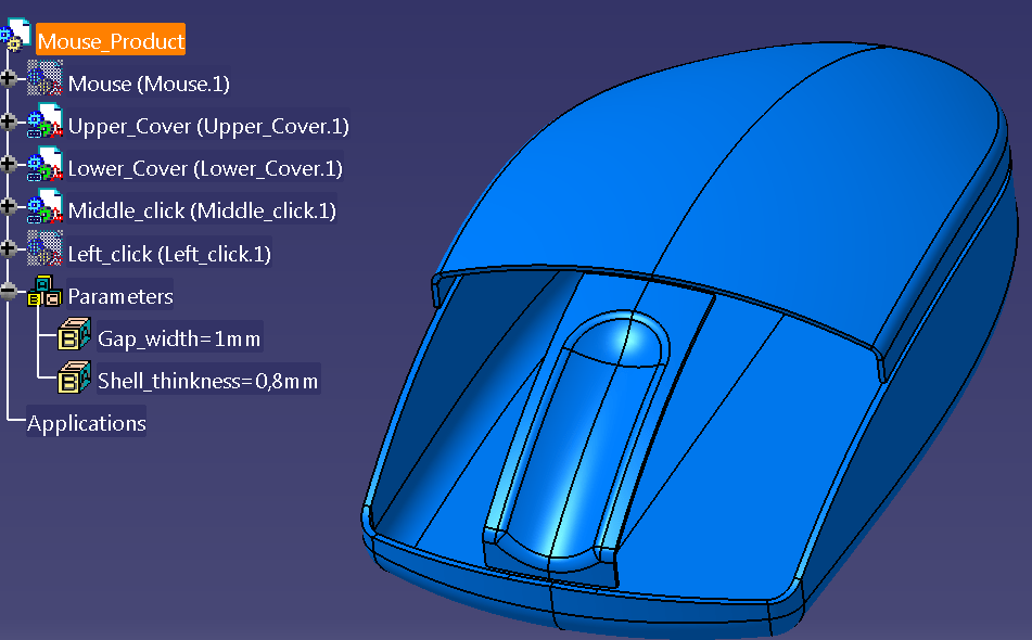
Based on the Published element in the Reference model, now you can create the other components. Therefore start adding 5 new parts by clicking the “Part” icon and when “New Part Origin Point” message pops up just click No.
After all 5 parts are added, on the Knowledge toolbar click on “Formula” icon and add to more Parameters to be used for your Mouse Design. Follow the setting in the “Formula: Product”: One parameter is called: “Gap_width” = 1mm and the other one I call it “Shell_thickness” = 0,8mm

MOUSE _ UPPER COVER_Part design
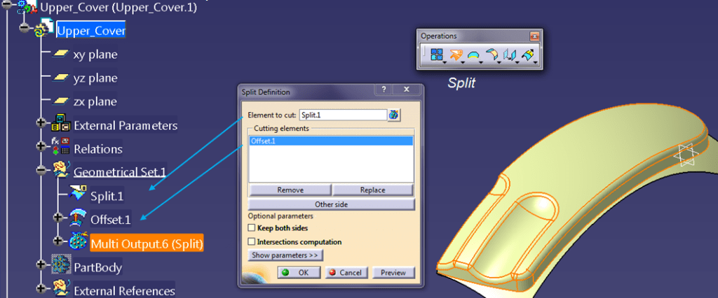
STEP 30:
Create the Upper Cover part by double clicking its “Geometrical Set” to make it as “In Work Object” and Switch to GSD Workbench. As the first feature create a “Split” between the Published “Outer_Skin” (as element to cut) and “Splitting _Surface” (as cutting element)

STEP 31:
The first previous Split is only to define the raw size of the Upper Cover but this is not really the right split you need. So to define the final size of the Part you must add and Offset surface having the value defined by a formula using the assembly assembly parameters, in this case the “Gap_Width”. So click on th “Offset” Icon,and follow the settings as show below:

STEP 32:
Now create a 2nd split this time with the right surface.
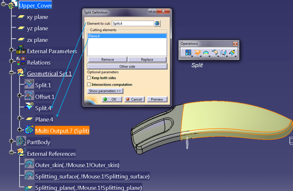
STEP 33:
Create a new plane with an Offset form the Published Splitting Plane, following similar settings for Offset value relater to assembly parameter “Gap_width”

STEP 34:
Split the Upper cover surface again with the previously created plane.
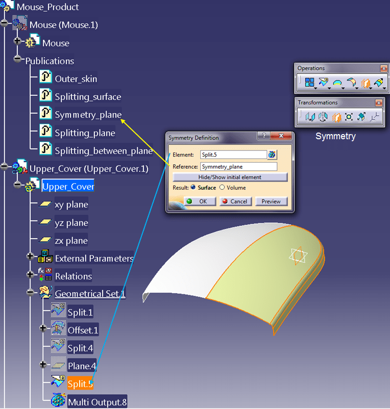
STEP 35:
Click on the Symmetry icon to mirror the upper surface versus the published Symmetry plane.
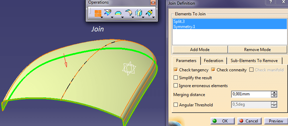
STEP 36:
Join the 2 upper surfaces.
STEP 37:
Switch to Part Design Workbench and add thickness to the upper surface also defining it´s value with a formula based on the Assembly parameter “Shell_thickness”.

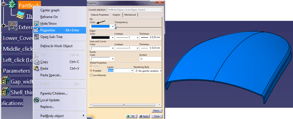
STEP 38:
Finally for a different more attractive appearance, if you want you can change the color like for example blue.
MOUSE _ LOWER COVER_Part design
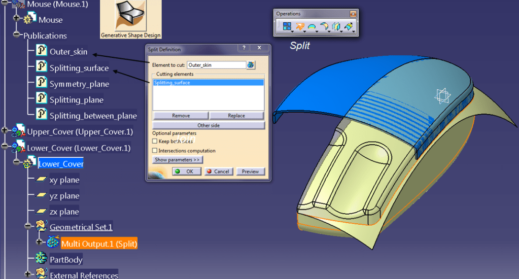
STEP 39:
The rest of the component parts are created in a similar way like the Upper Cover. All you need to do is to pay attention when you do the splits, use “Other side” button if necessary. For example for the Lower cover, you do the same split between the published “Outer_skin” versus the published “Splitting_surface”, but this time you only switch the splitting side.
STEP 40:
The same goes with the surface offset. For the lower cover the Offset is created on the reversed direction versus like for the Upper Cover.

STEP 41:
Do the 2nd Split by the previous offset.

STEP 42:
Because the Lower part is the housing for all the rest, here there is no need for the 3rd split like you did for the upper cover. So proceed directly with the symmetry. And of course create the Join surface with both sides.

STEP 43:
Switch to Part Design Workbench, and add Thickness and color in the same way like you did for Upper Cover.
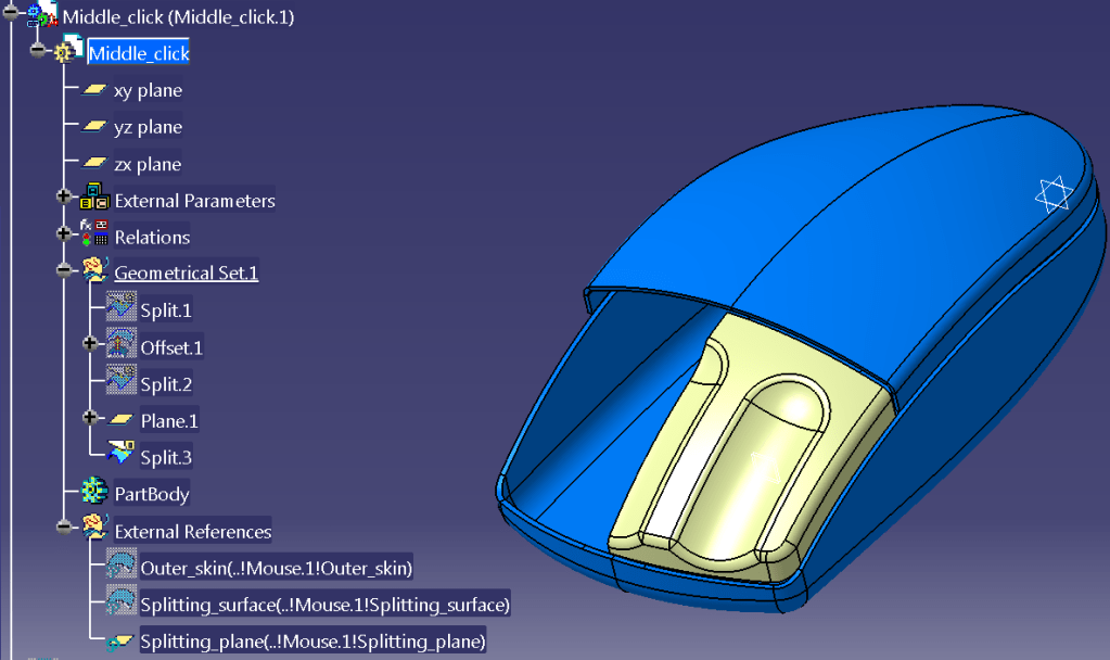
MOUSE _ MIDDLE CLICK_Part design
STEP 44:
For Middle Click the feature creation is exactly the same like for upper Cover. Do that and before to add thickness your part should look like this:
STEP 45:
Additionally to what you did at the Upper Cover, for the middle click you must add a split in the side: So for that, create a new plane with an Offset defined by a formula based on the Assembly parameter “Gap_width” and use the published “Splitting_between_plane” as reference for the offset.

STEP 46:
Create a new Split between the previously defined plane and the Middle Click surface.

STEP 47:
And the rest is made in the same way like for Upper cover. Create the Symmetry surface, create the Join Surface, and Switch to Part Design workbench and finish the part by adding thickness and color.
MOUSE _ LEFT CLICK_Part design
STEP 48:
For the Left Click, the design method is similar with Middle_Click, except that you don´t apply Symmetry.

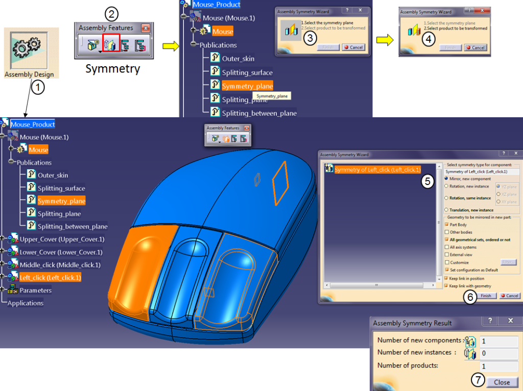
MOUSE _ RIGHT CLICK_Part design
STEP 49:
Until now all the 5 Component parts are created: The remaining is the Right_click part which in this exercise is exactly the mirror or the Left_Click. So double click on the Mouse_Product in the Model Tree and activate the Assembly Design workbench. In the Assembly Features, click on the Symmetry icon and follow the settings as shown below:
MOUSE _FINAL Assembly design
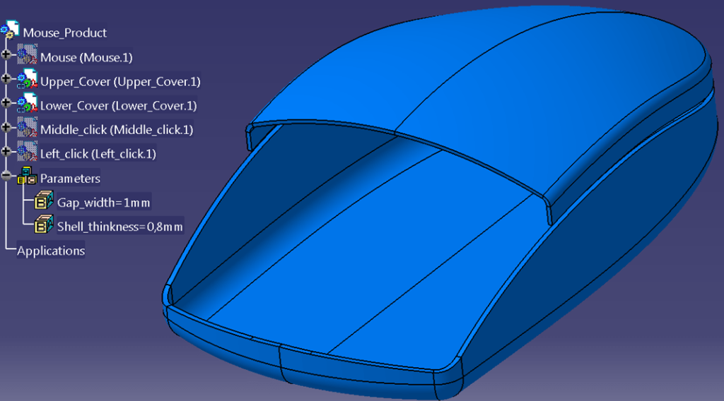
STEP 50:
And here it is, the Mouse Product Design is Finished.


In case you wish to simulate different design versions, you can easily change the parameters values and update your assembly accordingly.
Now before to save your work and close the session, go to File menu, and click on “Save Management…”. A new dialog window will open where you can control how do you want to save your work. I usuallw save everything in the same Folder so, I click on the CAT.Product and then I hit the “Save” button on the right side of the SM_Window. For the other parts, I simple click on “Propagate directory” button and CATIA will save all the rest in the same folder. Then click OK and you can close the CAD work session.

This exercise is also available as video version on my YouTube Channel as shown below:

The article offers helpful tips and thought-provoking ideas. Thanks for sharing your experience with us.
LikeLike
You’re welcome ;-). Thanks for reading as well.
LikeLike
You’re welcome. It’s my pleasure.
LikeLike