
Depending on the project complexity the CAD work regarldless the CAD platform can be done in different apporaches. You can create a part completelly from skratch OR you can reuse some data already defined that can be reused for different other component parts of the project (for example to use data from a skeleton sketch used for a PCB design but which can be also used to design a housing or a cover or any other component). There is no favourite approach. With any CAD software every mechanical design approach is equally effective. In this post I want to show you how to use the Top-Down approach in CREO Parametric with SheetMetal design workbench.
In the Top-Down approach in Sheetmetal development you don’t need to create your design concept completelly from skratch; you can easily use a skeleton sketch which for example has been used for other design components, maybe even used on multiple projects. So this skeleton must be obviously a shared data which you can access and use to build your part.
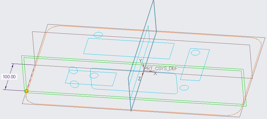
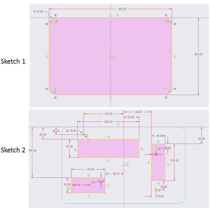
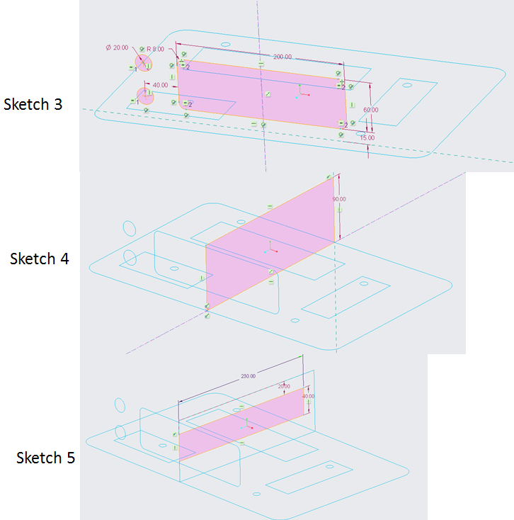
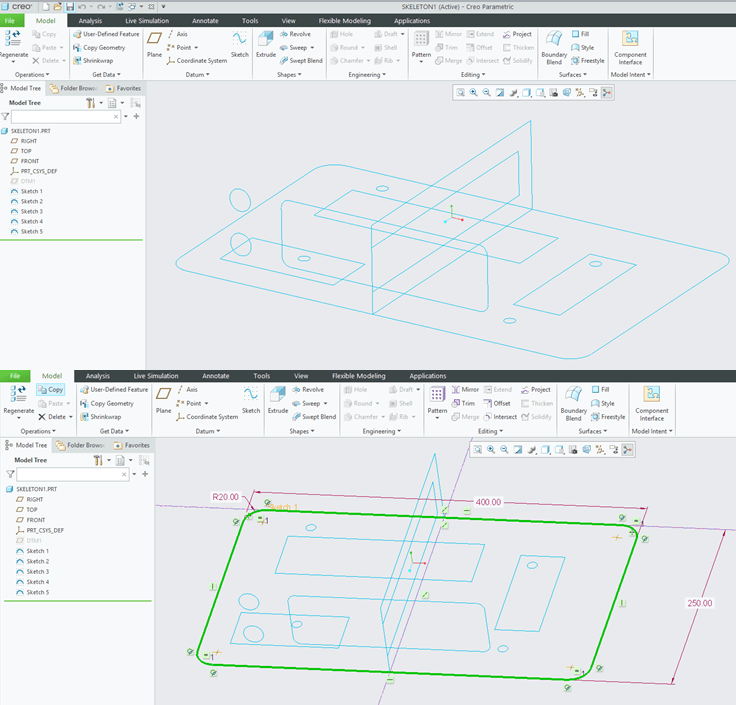
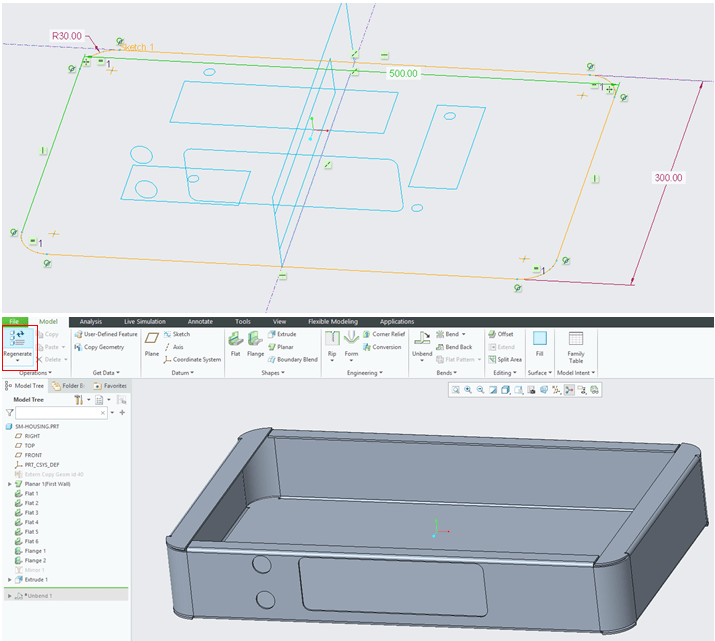
In this example the skeleton used to design the housing is made of 5 sketches and 1 additional plane. As shown below:

The skeleton dimensions are for example as shown below:
Based on these elements let’s create now the Sheet Metal Housing.
STEP 1.
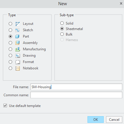
Create New Part selecting the sub-type: Sheetmetal
STEP 2.
To start your design you must import the data you need in order to continue your design work. In the Creo Sheetmetal workbench click on “Copy Geometry” icon and open the existing skeleton following the steps as shown below:
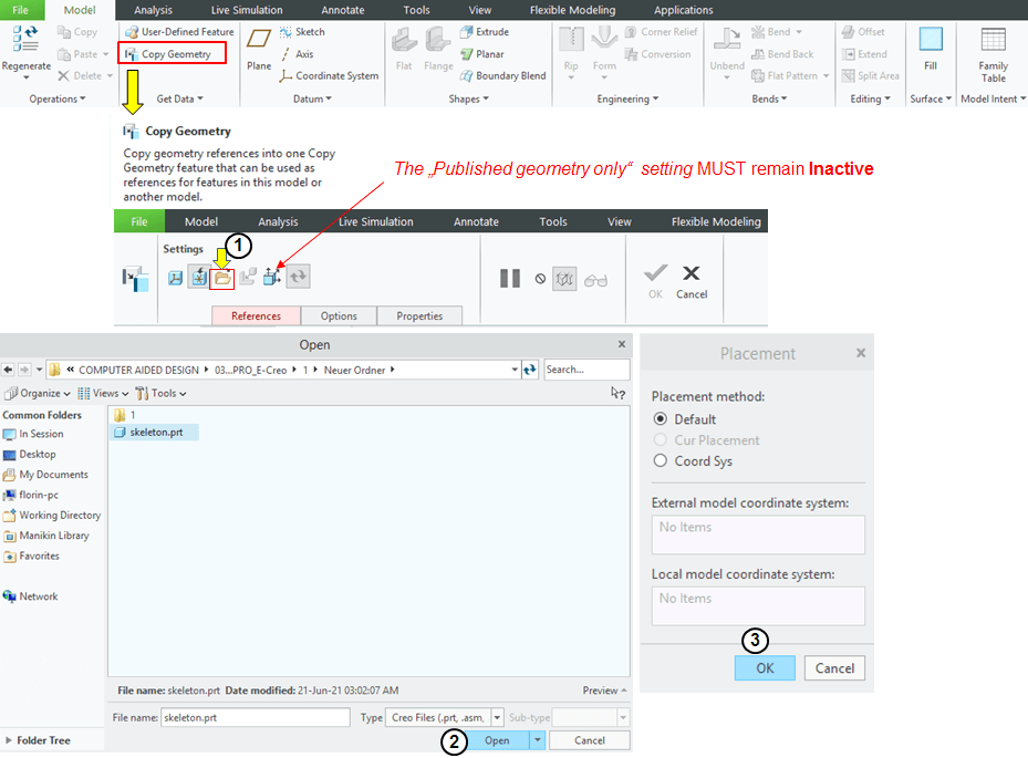
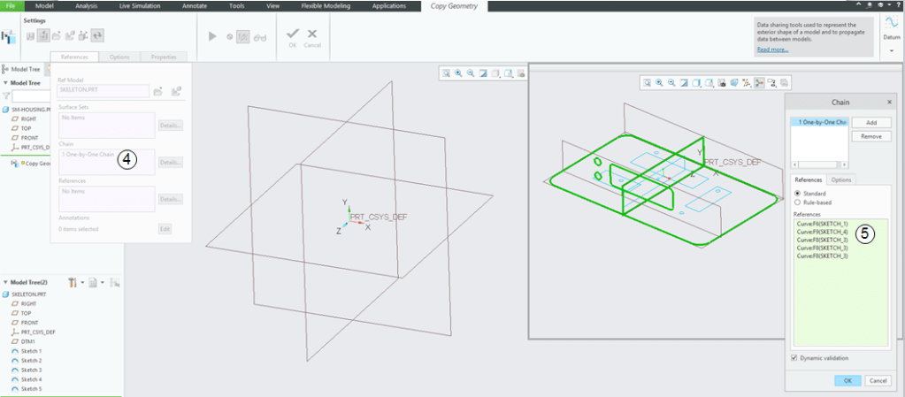
Then specify the references you would like to use ,in this example select the sketches 1, 3 and 4 as shown below. For multiple choises always hold the Ctrl button on your keyboard and with the left click pick all the necessary profiles. In the Settings make sure the option “Published geometry only” is NOT selected and then click on “Chain” box, select the base profile (Sketch 1) and eventually click on the option “Details…” and continue the selection as shown:
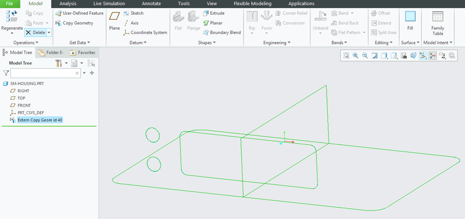
The necessary reference data from the external model is now copied and you can proceed with the housing design adding some sheetmetal stuff.
STEP 3.
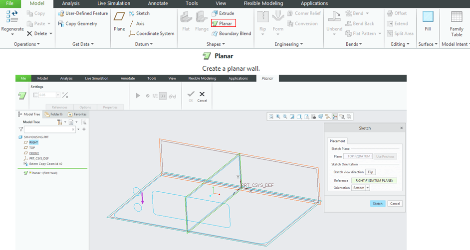
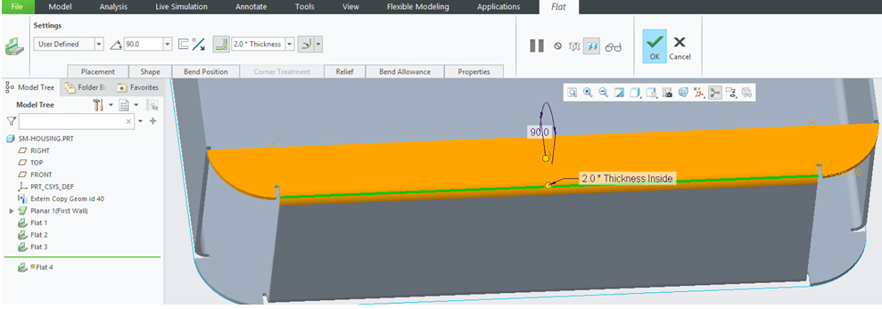
Start with a Planar wall and do the selections as shown:
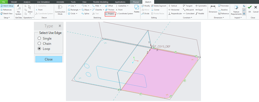
In Sketch Mode use the data you have just copied and project that on the sketch plane. In this case use the option “Loop” and select the bottom profile; As this model happent to be simetrical you don’t need the entire projection but just half of it. You build the half-housing and when done you simply mirror the whole thing. So draw a middle line to have a closed sketch and delete the lines in the left side.
Put a thickness of 2mm, make it towards inside and click OK.
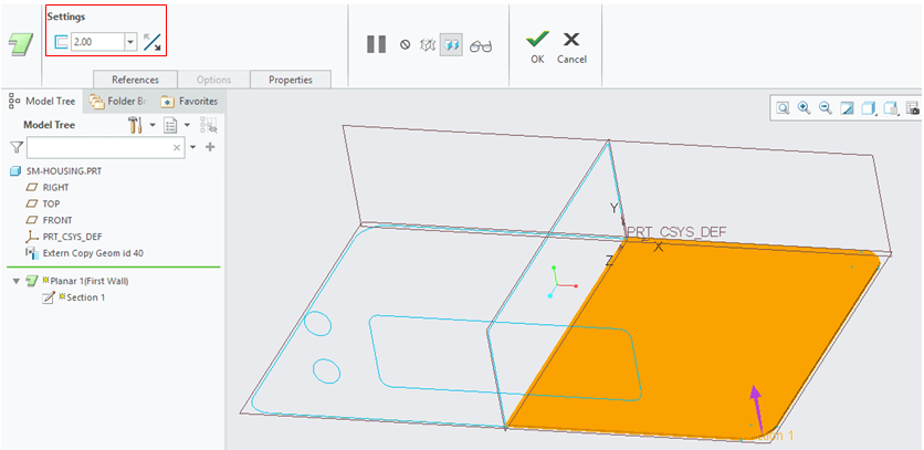
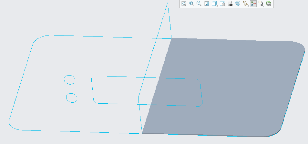
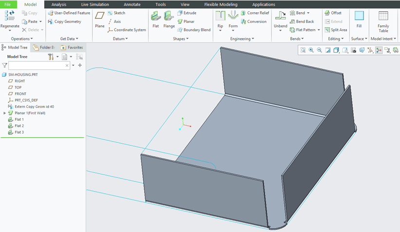
The Planar Wall looks like this.
STEP 4.
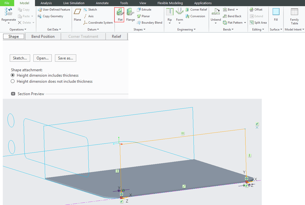
Next step is to create a Flat wall on the right side. For this, select the outside edge and be consistent using that during the design work. Make this first Flat in the upward direction. In a simple design the wall is directly added and you can easily change the parameters as you like. But in this example you want the wall to be driven by the external data in “Sketch 4” you’ve copied from the reference data, which is the the middle profile. So in the “Shape” tab keep the default setting “Height dimension includes thinkness” selected and click on “Sketch…” button. And then in the Sketch mode ask for the top line of the Flat Wall to be coincident with the top side vertex/line of the projected middle profile.
Exit the sketch and adjust the “Relief” as “Oblong” type and make it “Tangent to bend” then click OK.
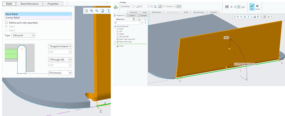
The Flat Wall is created.
STEP 5.
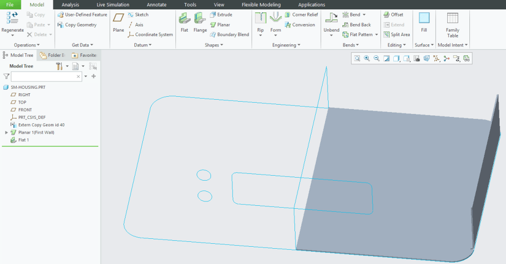
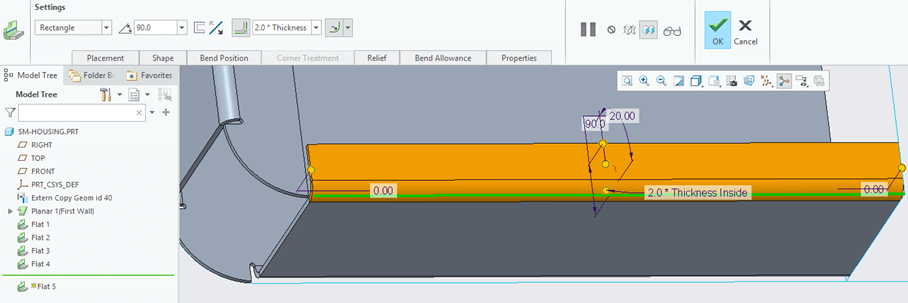
Now as the Flat Wall is created sidewise; the same must be done on front and rear side of the housing. You have here few options to do that. You can continue and create another 2 Flat walls manually in the same way as you just did with the first one, OR you can just copy (Ctrl+C) the Flat 1 and paste (Ctrl+V) it. Try to do it with Copy & Paste method. So then in the Model Tree do a Right-Click on the Flat 1, then Copy and then Paste (Ctrl+V). Creo will only need to know on which Edge you want to put this new Flat wall; so click on the outside edge (the same as you did for the 1st Flat). Like that normally the new Flat is instantly added.
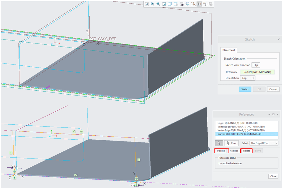
For specific profiles sometimes it might happen that Copy & Paste doesn’t really work as expected , you can still adjust anyway, soif that’s the case then after you have clicked on the edge where you want to put the wall, in the Flat definition window, click on “Shape” tab and then on “Sketck…” buton.
Here you can continue updating the references in such a way that this Flat 2 will be driven exactly as the Flat 1 is. Do that one more time for the other side,
…and now your design looks like this.
STEP 6.
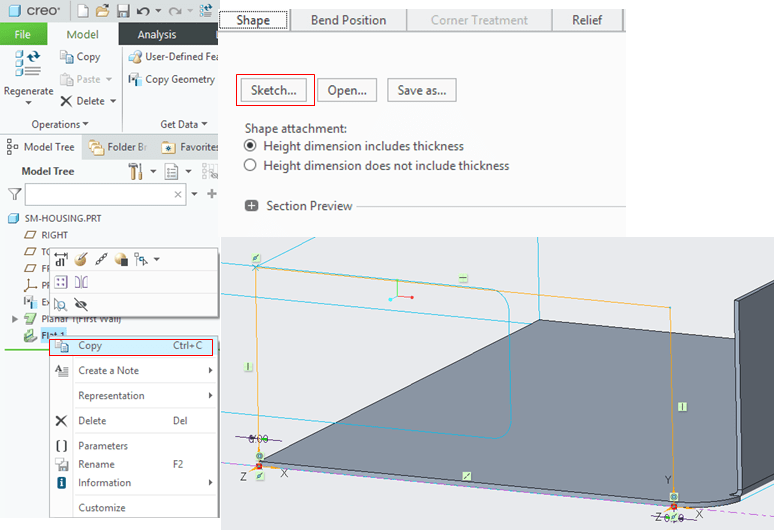
Further on, create another Flat on the top edge on the sidewise Flat. Click on the edge and then in the “Shape” tab keep the Shape attachement as it is and click on “Sketch…” button.
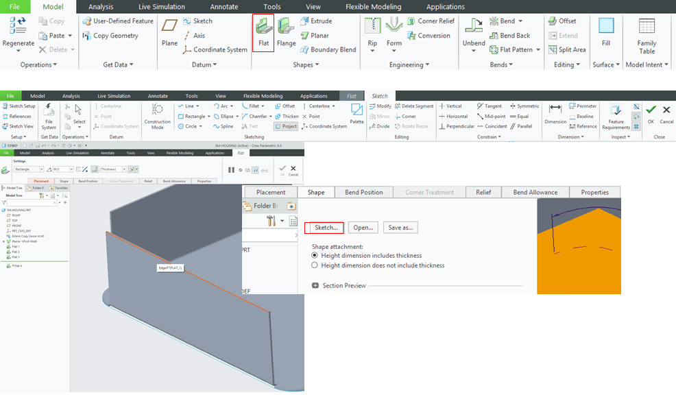
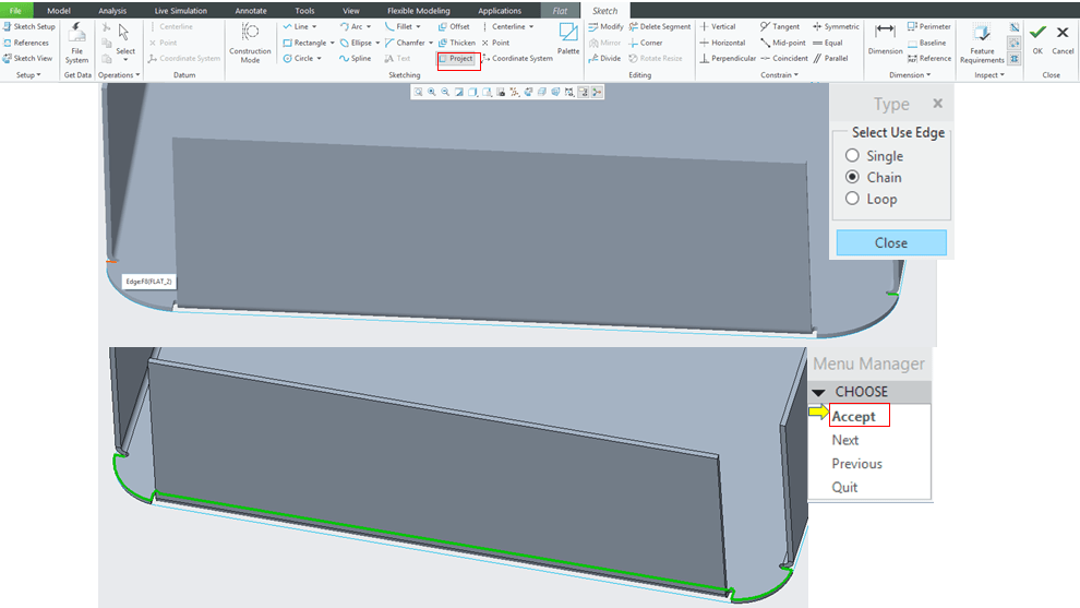
But this wall must have a very specific shape too, so in the sketch mode delete everything created by default and click the “Project” icon to create the specific wall shape. Choose the Type “Chain” select the edge to be projected and in Menu Manager click Accept.
Delete the unnecessary lines
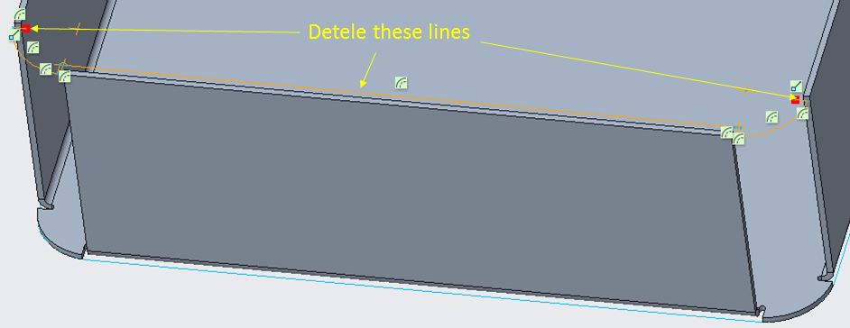
Click the “References” icon, select the outside surface and draw 3 new lines as shown.
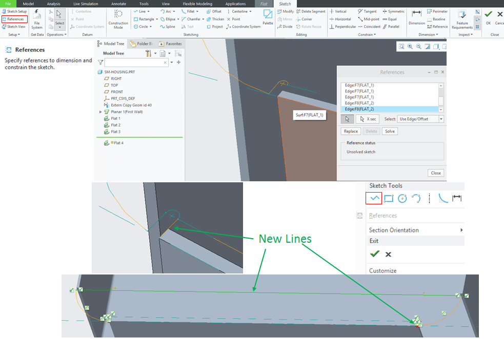
Exit the Sketch and in Flat settings mode just click OK.
STEP 7.
Create another 2 regular Flats on the other walls as shown; Use again the Copy (Ctrl+C) & Paste (Ctrl+V) method.
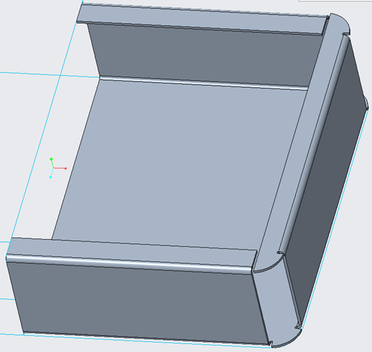
…and now your desing lookes like this.
STEP 8.
Now to close the housing corners, you must create a feature called “Flange”. So click on its icon and follow the settings as shown:
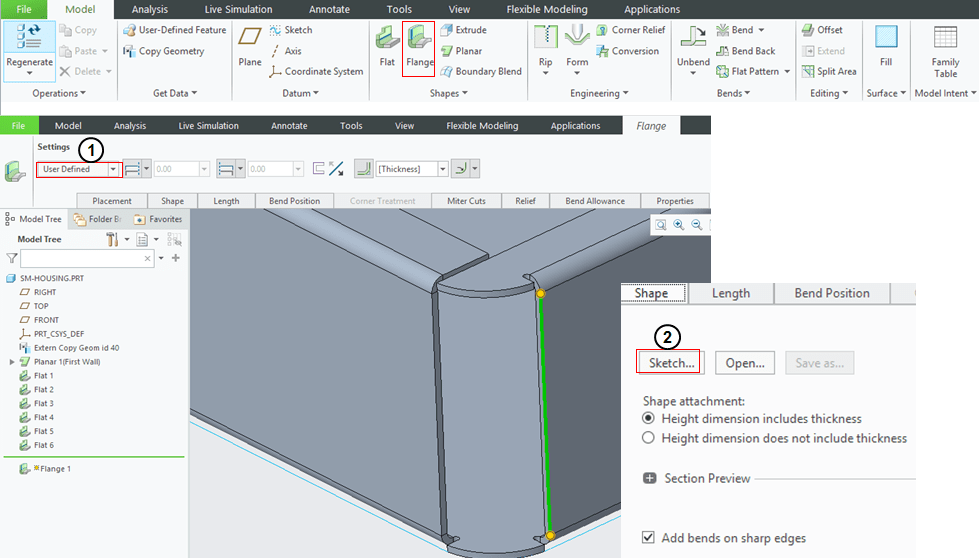
In case Creo puts anything by default just delete that an continue with the settings as shown. To create the sketch use again the projection and choose the type “Single”, be careful when you do the selection, click on the imported wireframe radius NOT on the Sheetmetal edge;
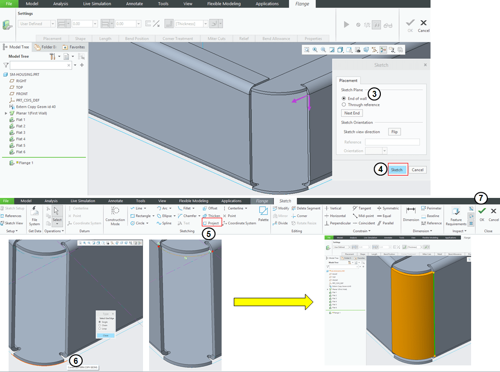
STEP 9.
Do that (step 8) one more time for the other corner…
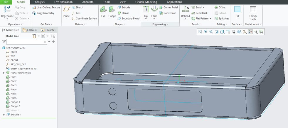
…and now your design looks like this.
STEP 10.
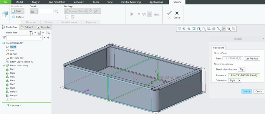
At this design stage you are ready to mirror the whole thing and finish the housing design. In the Model Tree pick the top of it and mirror your thing by picking the middle plane.

Now it’s important thou to click on the mirror feature in the Model Tree and hide it because it includes all data curves and references inside of it.
STEP 11.
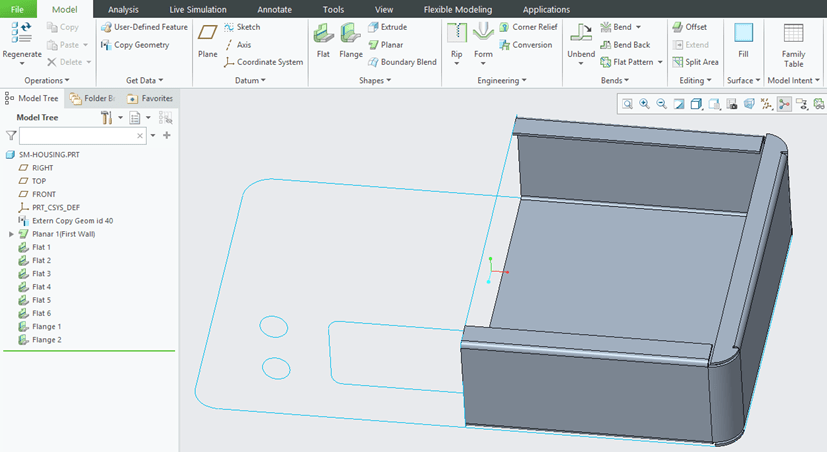
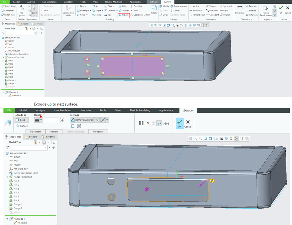
The last feature to create now is a cut-out that is done on the front wall. So click “Extrude” icon –>select the front surface, –>click on Sketch
–> click on Project and use the Type “Loop” in order to select the cut-outs–> Select the Depth as “Extrude up to next surface” and click OK.
STEP 12.
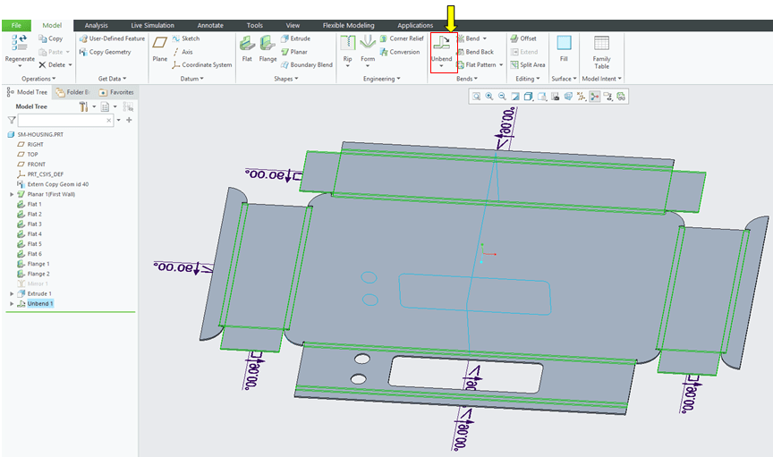
For a quick flat part hit the “Unbend” icon and see the result.
STEP 13. (for the design update)
For a last check, if you go back to the original Skeleton…
… and for example change the values as shown, by clicking the “Regenerate” icon for Housing data, the part will be automaticaly updated accordingly.
This exercise is also available as video version on my YouTube Channel as shown below:

Leave a comment