The mechanical description of a part is usually done by using simple geometrical form features such as lines, planes, circles or cylinders. But in many cases mechanical parts have complex geometrical structures and their form deviations must be described more specifically. Therefore when your product is getting complex in form (e.g. automobiles, airplanes, ships) with parts having nonplanar, noncylindrical, nonspherical features, to define their form deviations you must use profile tolerances. Such tolerances are specified as Line Profile Tolerance and Surface Profile Tolerance. In this post I am going to show you how LINE PROFILE TOLERANCE works.
Description
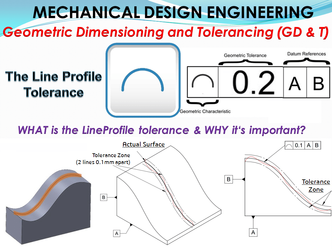
Line Profile tolerance is 2-dimensional geometrical tolerance that limits the amount of error for line elements relative to their true profile.
Form tolerances mostly concern real geometric features. But a line profile tolerance for example can be applied also on derived features such as the axis of a curved pipe.
Strictly speaking, straightness and circularity are special cases of the line profile. The line profile tolerance limits the deviations of a arbitrarily designed line, this being understood as a geometry element.
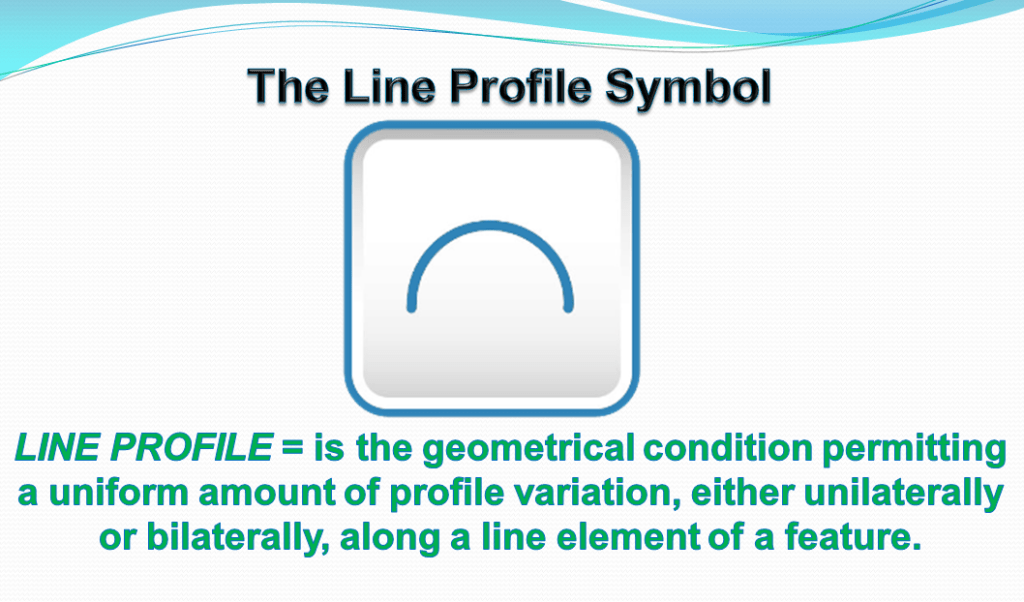
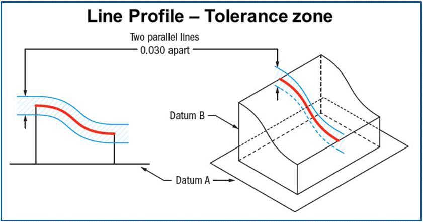
Symbol: -The symbol of line profile tolerance is an arc with no base line (as shown in figure 1.) This symbol is specified in the left compartment of the feature control frame and it is used to describe how close an object should be to a true line.
The Tolerance call out: – The feature control frame includes the line profile symbol and tolerance value followed by up to 3 datum references, if needed.
How Does It Work?
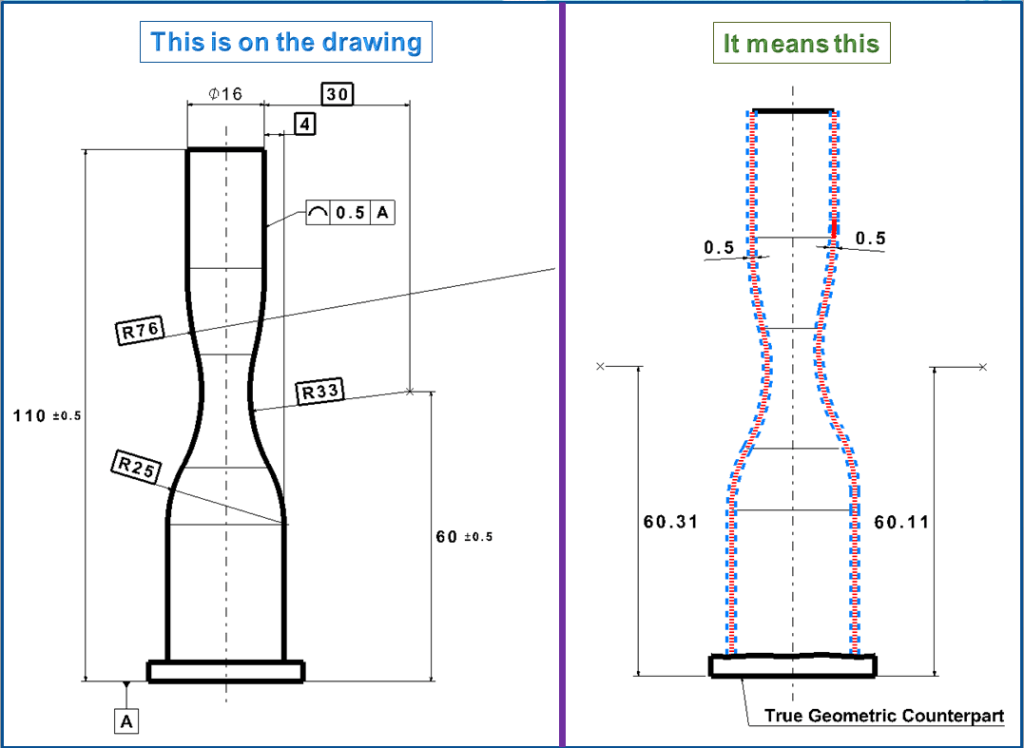
Every profile tolerance relies on a basic profile. (See Fig. 3). This is the profiled feature’s nominal shape usually defined in a drawing view with basic dimensions. A profile tolerance zone is generated by offsetting each point on the basic profile in a direction normal to the basic profile at that point. This offsetting creates a “band” that follows the basic profile. The part feature (or 2-D element thereof) shall be contained within the profile tolerance zone. In addition, the surface (or 2-D element) shall “blend” everywhere. We interpret this to mean it shall be tangent-continuous.
If it is called out on a surface, like a radius on a part – line profile would specify how much that cross-section could vary from a true curved radius. Line Profile takes a cross section at any point along the surface and sets a tolerance zone on either side of the profile. The profile of a line callout can also be set with an all-around leader or given a specific range, for example the outline of a curved feature or the cross-sectional profile of a wing.
Tolerated geometry elements – The Basic Profile
You can specify the basic profile by any method that defines a unique and unambiguous shape for the controlled feature. The most common methods are projecting a 3-D figure onto a plane or taking cross sections through the figure. The resulting 2-D profile is shown in a drawing view. We call this 2-D graphical representation the profile outline. Basic dimensions are specified for the basic profile to define each of its elements. Such basic dimensions may include lengths, diameters, radii, and angles. Alternatively, a coordinate grid system might be established, with points or nodes on the basic profile listed in a table.
Yet another method is to provide one or more mathematical formulas that define the elements of the basic profile, perhaps accompanied by one or more basically dimensioned nodes or end points. A CAD/CAM model’s digital representation of a basic profile also qualifies. It’s not necessary to attach basic dimensions to the model since the computer already “understands” the ones and zeros that define it. In a paperless manufacturing environment, the “undimensioned” model along with a profile tolerance specification are all that’s needed by automated equipment to make and inspect the profiled feature. This method accommodates truly 3-D–profiled features having varying cross sections, such as a turbine blade or an automobile windshield.
While any of these or other methods could be used, the designer must take into account the expected manufacturing methods and ensure that the basic profile specifications are accessible and usable. This consideration may prescribe multiple 2-D drawing views to show, for example, an airplane wing at several different cross sections.
For simple basic form elements such as circles or planes, their ideal form is known. But in the case of more complex forms, however, the ideal form or nominal feature must be first determined, with theoretically precise dimensions (with values indicated inside a rectangular frame on the drawing) or as a computer-internal 3D data set.
For the representation with theoretical dimensions the following rule applies:
Nominal feature rule – If the Nominal Feature (ideal form) will be described using the theoretical dimension then the corresponding right-angled axis of coordinates and regular circle divisions applied, are also theoretically accurate.
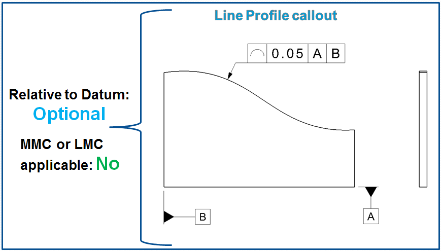
Datums – Profile tolerances first of all limit the form of the tolerated profile and second, like other form tolerances, in general have no datums. DIN EN ISO 1101: 2006 at first specifies them in terms of form tolerances. But in the same time it is also possible to determine the ideal profile relative to one or more datum elements a.k.a. DRF (Datum Reference Frame).
- if datum references are specified, the line elements are oriented relative to the datums specified;
- if no datum references are specified, the line elements are being controlled for form only assumed to be equal bilateral unless otherwise specified.
Where a profile tolerance need only control a feature’s shape, it’s unnecessary to relate the profile tolerance zone to any DRF. Thus, there are many applications where the profile feature control frame should have no datum references.
Where the tolerance must also control the orientation, or orientation
and location of the profiled feature, the tolerance zone shall be related to a DRF. Depending on design requirements, the DRF may require one, two, or three datum references in the profile feature control frame.
Profile tolerances – (line and surface) are therefore the most varied type of tolerances (They cannot appear only as runout tolerances). The other types of tolerance are there in addition to make the tolerancing clearer.
Tolerance zone
Limit deviation – As long as profile tolerances occur as form or direction tolerances, the limit deviation is equal to the tolerance t. But if the ideal line, meaning the middle of the tolerance zone, is linked at one position by datums, then the actual contour may not deviate from it by more than t/2 on either side; the limit deviation is therefore ± t/2. But I will explain this in more detail in another article about the location tolerances.

In contrast to [ASM94], the ISO standardization does not recognize a one-sided tolerance zone. If it is needed (e.g. for molded parts with the same nominal contour, which should fit into each other) you can add a corresponding note to make the tolerance specification complete. (see FIG. 9 below)
A feature control frame bearing the “line profile” symbol specifies a tolerance zone plane containing a 2-D profile tolerance zone having a total width equal to the tolerance value. As the entire feature surface is swept by the tolerance zone plane, its intersection with the plane shall everywhere be contained within the tolerance zone. Where no DRF is referenced, the tolerance plane’s orientation and sweep shall be normal to the basic profile at each point along the profile.
For a revolute, such as shown in Fig. 6, the plane shall sweep radially about an axis. Within the plane, the orientation and location of the tolerance zone may adjust continuously to the part surface while sweeping. Alternatively, one or two datums may be referenced as necessary to restrain the orientation of the tolerance plane as it sweeps. Depending on the datums chosen, the DRF might also restrain the orientation of the tolerance zone within the sweeping plane.
Any basic dimensions that locate the zone relative to the referenced DRF will restrain the zone’s location as well. Addition of a secondary or tertiary datum reference could arrest for the zone all three degrees of translation. For a nominally straight surface, the sweeping plane would then generate a 3-D zone identical to that specified by the “surface profile” symbol. To limit the control to 2-D, then, a designer must be careful not to overrestrain the tolerance plane and zone.
When is the Line Profile tolerance used?
Line Profile tolerance is used in situations where parts or objects have changing cross sections throughout the length. A common use of line profile would be if you were comparing a curving surface such as the hood of a car, or an airplane wing. With an airplane wing, each cross-section would need to be a different profile shape and require multiple measurements to ensure at each location the profile tolerance is met. Both profiles of a line or profile of a surface can be called out on such surfaces.
Application of a profile tolerance is a 3-step process:
- define the basic profile,
- define the tolerance zone disposition relative to the basic profile, and
- attach a profile feature control frame.
FAQ: How can I get the orientation restraint I need from a DRF (Datum Reference Frame) without getting location restraint I don’t want?
A: Currently, there’s no symbolic way to “switch off” a DRF’s origins. In the rare case where basic dimensions define the basic profile, but you don’t want the location restraint, you’ll have to add a note to the drawing.
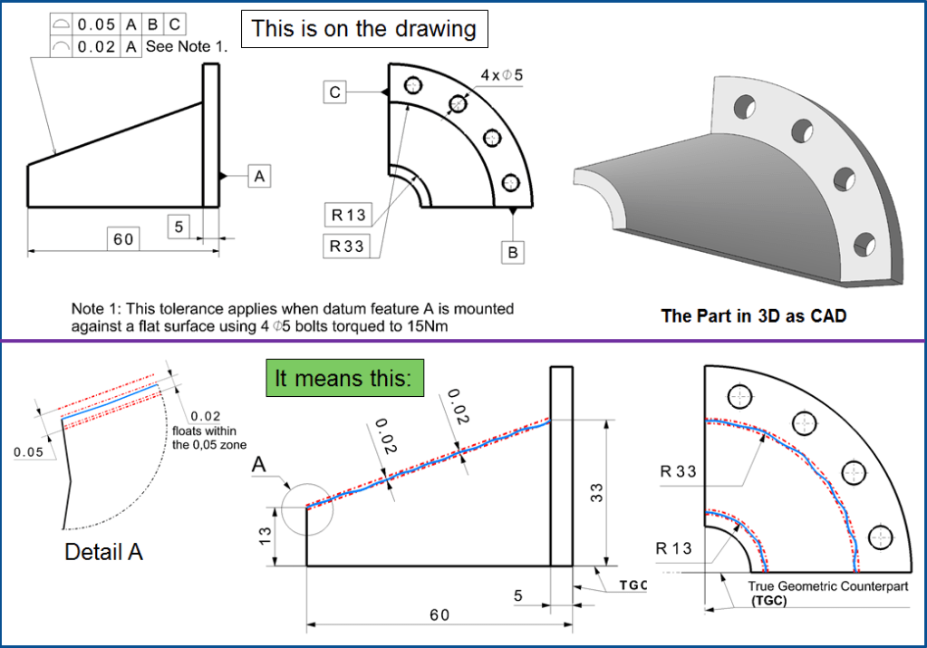
Example 1. Curved surface
If you have a curved surface that would need to be in specification along all of its cross-sections, the line profile tolerance works as shown below.
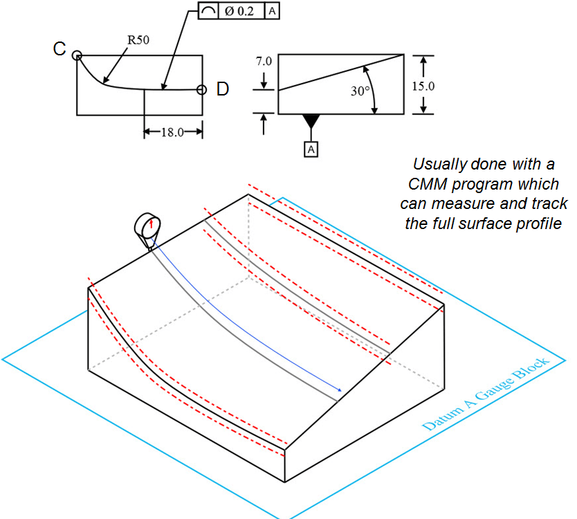
Note: All dimensionless values are considered basic.
This could be considered an advanced curve that could only be controlled with the use of a profile tolerance if required. The part is only measured from point C to D for each cross-section.
Note: The profile of a line tolerance does not control the specific dimension that every surface point is located – that is done by the dimensions of the part. It only controls how tightly the points fall into a “true” curve, similar to the circularity tolerance.
Typical cases for the definition of the ideal profile with and without references using the example of control cams are presented as follows:
Example 2. Polyline with form tolerance.
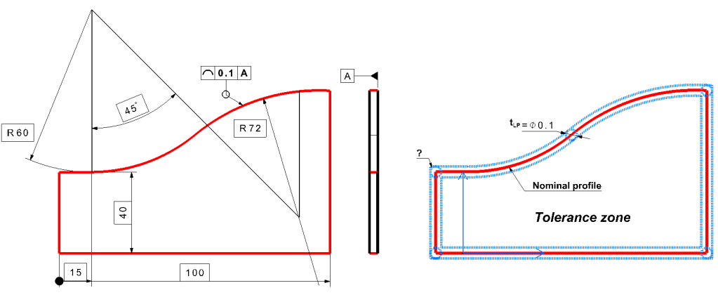
The nominal profile of the curved stencil made of thin sheet metal is determined by 2 tangent circular arcs and an angle of 45 °, there are also two tangential straight lines. The tolerated profile ends at the corners. For simplicity I´ve omitted here the dimensions and tolerances of the other elements of the stencil. Although this goes as a Form tolerance, it is strongly advisable to indicate the primary reference plane A. The measuring device then measures parallel to the main direction of the plate. (the same applied to the examples 4, 6 and 7 as showed next)
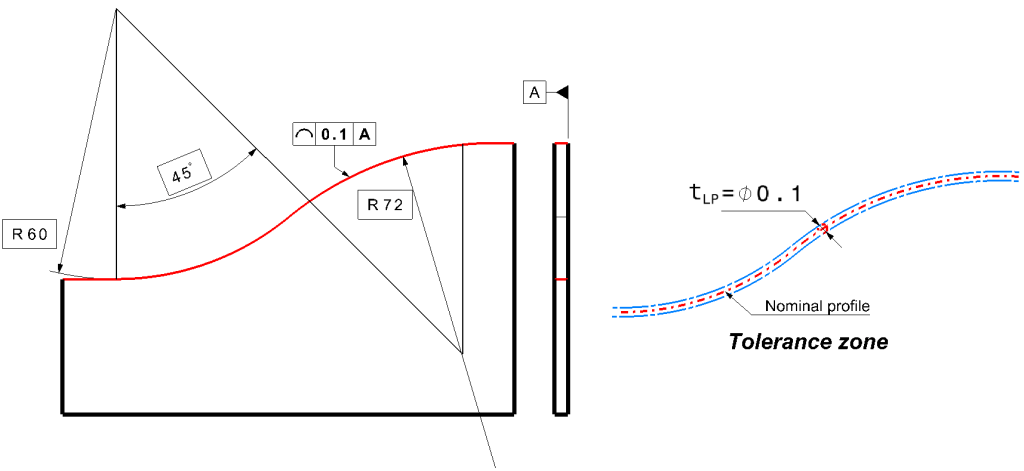
The tolerance zone is two equidistant at a distance of ± tLP/2 limited by the nominal profile. It can imagined as, clear circles of a diameter of ØtLP drawn around the ideal profile; their envelopes form the tolerance limits. The tolerance zone extends over the entire length of the tolerated line. If it is not clear how far this extends; its length can be indicated by a thick dash-dotted line marked with a tolerance arrow on it. Like with all form tolerances, the line profile tolerance zone can be freely moved and rotated, but remains perpendicular to reference A.
Example 3. Polyline with positioned tolerance zone
The curve template corresponds to Example 1, however in this case is not only the form, but also the location of the tolerance zone defined through a complete reference system. These are theoretically exact dimensions required between the reference elements and the tolerated profile. Additionally is specified a tolerance zone lying inwards on one side (according to [ASM 94]).

Example 4. All around closed line profile
Here is the entire outline of the stencil tolerated as a profile. According to DIN EN ISO 1101: 2006, for this type of entry the tolerance arrow is bent and on the bending point there is a small circle indicated. In the past, “all around” specification was used instead, noted on the tolerance frame. According to Nominal feature rule mentioned above, the right angles of the profile apply as theoretically accurate.
According to DIN ISO 1660, on corners results an outward rounded tolerance zone, meaning that the profile should have radii at Maximum Material Condition instead of corners. I think that makes little sense; the tolerance zone should e.g. also run angularly on the outside at corners (according to [ASM 94]).
Example 5. Profile dimensioned in different points
The upper ends of the vertical dimension arrows form the support points in which the nominal profile is determined (see DIN ISO 1660). Imaginable is again to draw circles of Ø0.4 mm around these points and as result build their envelopes (for example as Splines – Curves). The deviation of the tolerance limits between the support points is not precisely defined. The representation therefore requires a relative sufficiently tight space on tolerance zone for supporting points. The tolerated profile ends at the top right at the bend, similar to Example 2 and 3.

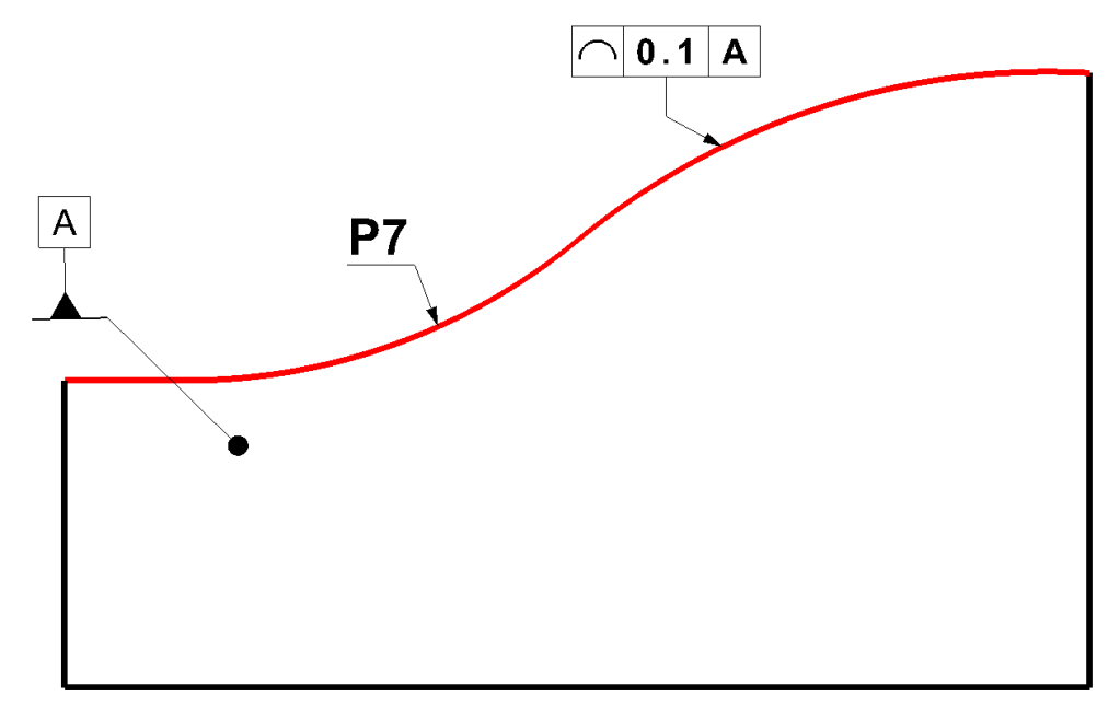
Example 6. Internally computer defined profile
The nominal profile is saved on the computer memory, in digitized form after a scan – -for example as “P7“- or in the form of a math formula. Meaning that there is no need for dimensioning. But if apart from the primary reference A further references occur, then the nominal profile to them must be defined with theoretical dimensions.
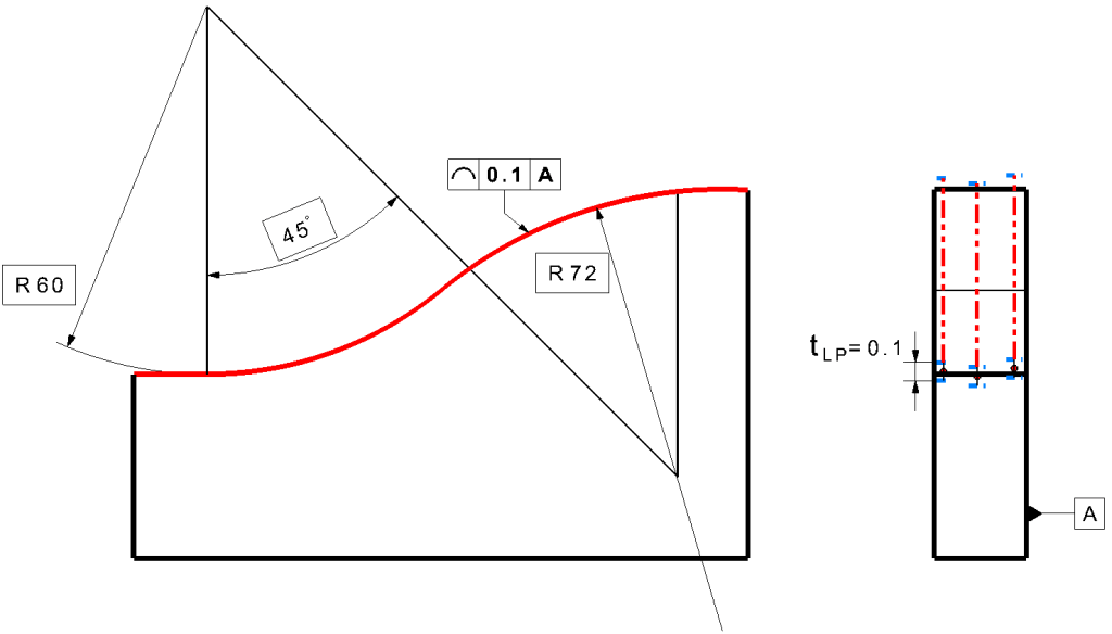
Example 7. Individual line profiles in any area
In contrast to Figure 8 the workpiece here has a considerable thickness. In this case the tolerance applies to each individual line profile that is parallel to reference A.
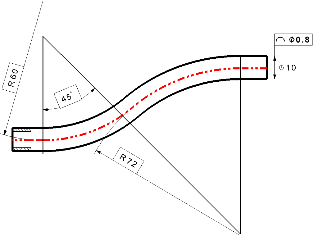
Example 8. Profile of a pipe axis
Not included in DIN ISO 1660, but quite conceivable is the application of the line profile tolerance for example on the axis of a pipe, (on a derived features). The tolerance zone in this case has a tubular shape. The nominal profile could e.g. also be spatially curved and provided with datum references.
Gauging / Measurement
Testing: As long as the profile tolerance only acts as a form tolerance, meaning that the tolerance zone is movable and rotatable (a primary datum that only determines the main direction, doesn´t disturb, see Figure 8 , 10, 12 and 13), then the actual deviation is evaluated according to the Least Material Condition rule , as follows:
LMC Rule – The form deviation results at Least Material Condition in which boundary lines and surfaces are pushed up from the tolerated geometrical element in such a way that these limits enclose it and the distance between them becomes a minimum; this distance is the form deviation.
You can for example prepare a test stencil (which corresponds to the maximum material limit of the profile, in Figure 8 in the upper line, and Figure 10 on the outer boundary line of the tolerance zone) and check whether they are aligned with the workpiece so that the remaining distance between stencil and workpiece does not become larger than tLP; like that the actual profile remains within the tolerance zone.
In Figure 13, a sufficient number of individual lines are checked in this way.
If on the other hand a complete datums system is available, the tolerance zone is defined accordingly; thus the Least Material Condition does not apply.
In most cases the line profile tolerances are checked with a coordinate measuring machine (CMM), especially with mathematical or numerically defined lines.
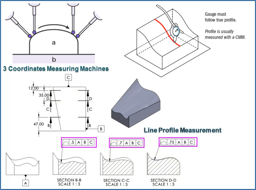
Profile of a line is measured using a gauge that is referenced to the true profile at the given specific cross-section. Because there are an infinite amount of 2D cross-sections of any part, the number or locations of measurement points can be specified on the drawing. Profile is usually measured using a CMM for more complex geometries.
The line profile tolerance measurement is analogous to measurement for straightness tolerances. The line profile measurement It´s a 2-D control of a feature’s individual cross-sectional elements.
Relation to Other GD&T Symbols
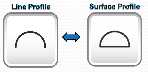
Line Profile is of course closely related to Surface Profile. The difference being that Line Profile takes only the measurement at a specific cross-section and does not take into account the variance of one cross-section to the next.
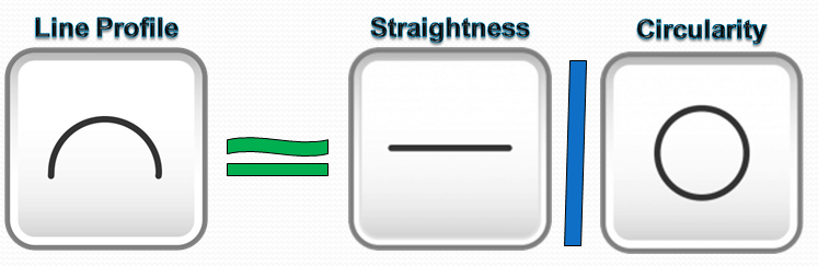
Line Profile can also be thought to be similar to straightness or circularity. All three tolerance symbols specify how much a cross-section can vary whether in a straight line, a circle or in a custom profile shape. They all have a tolerance zone existing of parallel lines surrounding the measured profile in a 2-Dimensional cross-section.
Final Notes
Sometimes a Line Profile tolerance is used in conjunction with Surface Profile tolerance. In these cases, the line profile tolerance will be tighter than the surface tolerance. This ensures that along any specific cross section of the profile, the profile remains true, while also ensuring that each cross section of the part would be within a wider tolerance range when compared together.

Hi Florin,
Thank you for your effort to create this deep researched explanation. I appreciate it!
I would like to ask if you have information on how we can mathematically calculate the difference between the Line profile and the surface profile. I mean how we can determine what is the equation to apply the tolerance of the line profile to the whole surface and vice versa.
Thank you for your time and looking forward to see your respond.
Bill
LikeLike
Hi Bill
I also appreciate you for reading my posts about GD&T. Let me just mention that all these posts are a collection of my own design engineering experice for almost 20 years. I am happy to share all these here on my blog so that other mechanical engineers can apply the same for their work. GD &T is fundamental knowlegde when we design something and we want that object to do its job for what was intended.
Now regarding to your question my advice is to make things simple to understand for all the people involved in your product design. This is exactly what GD&T was created for namely: to simplify the engineering language.
There are 14 types of geometrical tolerances which cover all the possible complexity of a part. We don’t need to use all 14 types at the same frequency. The most commonly used are the following 5: the Straightness,the Flatness, the Circularity, the Position and the Perpendicularity.
All the rest are a combination of these 5 and they are used in special cases, depending on the part complexity.
The Line Profile and Surface Profiles are special cases of Straightness and Circularity, they both work in analogous way.
You don’t need to apply any special equation to determine a conversion between line profile vs. surface profile tolerance. The only difference is that the Surface Profile tolerance provides a complete 3D control of a feature’s total surface, while the Line Profile provides 2D control of a feature’s individual cross-sectional element, that’s all. You can use any to them to define your part according to what exaclty do you want to control (also feel free to review my posts related to each of them)
In case your part has surfaces that can be clearly defined by the 5 geometric tolerances as I’ve mentioned earlier then strongly suggest you to use those. Consider the Line or Surface profile tolerances ONLY as a back-up solution, becasue these both Profile tolerances are high cost related. Just Keep your design as simple as possible. Make it User Friendly and create great User exeprience. at a good price.
If you have other questions about GD&T methods, feel free to ask me anytime, I’ll be honored to share my knowledge with you.
I will also add more posts related to GD&T on my blog, you can always follow that as well.
Best regards,
Florin 😉
LikeLike
I lve what youu guyys arre up too. Thiss sot oof cever work annd coverage!
Keep up the great works guys I’ve aded you guys to blogroll.
LikeLike
Pretty nice post. I simply stukbled upon your blog annd wanted tto mention thatt I’ve really
loved surfijg afound your bog posts. In anny case I will bee
subscribung for yyour fsed annd I hoope youu write gain very
soon!
LikeLike
Exellent post. I wass checkoing contiinuously this blo
aand I’m impressed! Verry helpful information specifically the last part 🙂
I car for suchh information a lot. I waas seeking this certain infordmation for
a long time. Thank you and good luck.
LikeLike
Howdy! This iss mmy first comment here sso I just wamted to giove a quick shoout ouut annd tell yoou I really enjhoy reading yyour posts.
Can youu recommend any other blogs/websites/forums that deal with thee samke topics?
Thaznks a ton!
LikeLike
Youur mode off describing alll in thiis piecce off wriging iis trulpy nice, every one
bee able tto effortlessly khow it, Thanks a lot.
LikeLike
🙂 😉
LikeLike