For quite a long time mechanical parts were controled based on their regular forms such as planar form, cylindrical form or spherical form, but when parts become more complex in form such measurements based on simple features were not possible anymore. Such irregularly shaped profiled features couldn’t be geometrically controlled until 1966 when the first edition of Y14.5 introduced “the line profile ” and “the surface profile” characteristic symbols and feature control frames for controlling profiled features. The 1973 revision of Y14.5 introduced datum references in profile feature control frames. Finally, designers could apply all the power and precision of GD&T to nearly every imaginable type of part feature. Later on the 1982 and 1994 revisions of Y14.5 enhanced the flexibility of profile tolerancing to the extent that now just about every characteristic of just about every type of feature (including planes and simple features of size) can be controlled with a profile tolerance. In this post I wish to show you how SURFACE PROFILE TOLERANCE Works.
Description
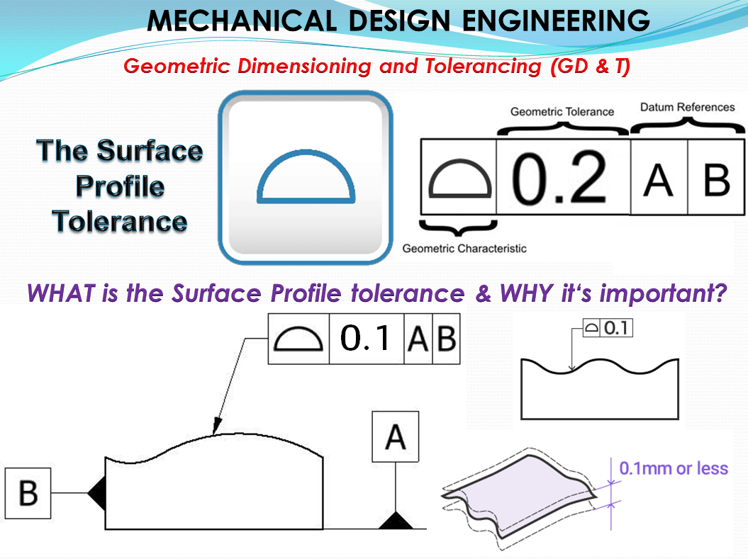
Surface Profile tolerance is a 3-dimensional tolerance that limits the amount of error a surface can have relative to its true profile.
Usually, when surface profile is required, there are no tolerances on the dimensions that describe the surface and use the GD&T callout to give the acceptable range.
Symbol: The symbol of surface profile tolerance is a closed semicircle (as shown in figure 1) and can be indicated on any area (in in practice, casually being referred to as “bread roll tolerance”). This symbol is specified in the left compartment of the feature control frame and it is used to describe how close an object should be to a true surface.

The Tolerance call out: – The Surface profile tolerance (acc. to DIN EN ISO 1101 “Profile of any surface”). Extends the Line Profile with one dimension. Therefore what is valid for Line Profile tolerances analogously applies for Surface Profile too.

How Does It Work?
The way how Surface Profile tolerance works is analogous with Line Profile Tolerance (see the Line Profile related article) The only difference is that the Surface Profile provides complete 3-D control of a feature’s total surface, while the Line Profile provides 2-D control of a feature’s individual cross-sectional elements. Either type of control may be related to a DRF (Datum Reference Frame).
Tolerated geometry elements – The Basic Profile
For Surface Profile tolerance exactly the same principle of basic profile applies as I explained in the Line Profile related article.
Application examples: In general real surfaces are tolerated. Fig. 3 gives some typical examples (for more see DIN ISO 1660).

a) Curved surface – The tolerated area corresponds to a simple line profile in however, the tolerance zone extends to a straight line on the whole width of the surface. All types of nominal feature defined for Line Profile tolerances (except the case with pipe axis) can be also applied on Surface Profile tolerances as references. A Primary reference is in this case not absolutely necessary. Without a specified datum, the tolerated surface can be used anywhere on the workpiece. With a primary reference A added, on the other hand, the Tolerance zone are perpendicular to datum A; can have a reference or f it would be completely fixed.
b) Composite surface – made up of several simple features that work together to fulfill a function like for example a dovetail guiding part. What´s mentioned here as a whole with the term “Profile” refers to a “Common tolerance Zone” CZ (the use of a broad dash-dotted line is also conceivable). The additional specification of a reference or a reference system is possible (see Figure 4). The limits of the tolerance zone are equidistant areas to the nominal profile at a distance of ± tSP/2, imaginable as an envelope over spheres of ØtSP whose midpoints lie on the ideal profile. (Regarding the “corners” of the tolerance zone must run at Maximum angle acc. to ASM 94). The counterpart of the dovetail guiding part (the slider) must have different nominal dimensions here because the tolerance zone is in the middle.
c) Spherical surface – Regular surfaces such as spheres or cones (see Figure 4) cannot be completely controlled only with basic form tolerances. To do that properly we must use the Surface Profile tolerance. Of course, like mentioned above or as shown in Figure 4 datum references can be specified as well.
Included tolerances. it is recommended to clearly start out from the tolerance zone. In the case of the dovetail guiding part for example, Figure 3(b), this is obviously limited to various deviations, such as the flatness and the parallelism or the angularity of the individual guideways, the parallelism of their line elements and the curvature and twist of the entire guiding part. Form deviations of any kind (including the line profile deviations), can be measured perpendicular to the nominal profile, and must never be greater than the surface profile tolerance tSP.
Possibilities to define the reference datums: The surface on the dovetail guiding part shown in Figure 3 (b) is only set in itself but its position to other surfaces is “floating”. This is useful if the function is only the sufficiently precise guidance for the required counterpart, e.g. with a vice that is attached to a workbench. But In a machine vise for a drill, the parallelism to the base surface must be also used.(reference for direction only, without ideal distance). In contrast, on an element for a machine tooling with modular system a complete reference system is required.
Different options for tolerating a cone are shown in Figure 4 below:
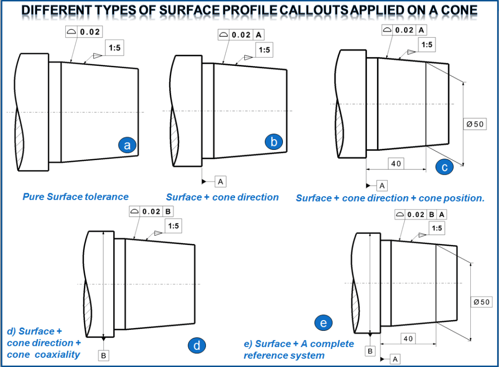
a) Pure form tolerance (according to e. g. a cylindrical form tolerance). The diameters result from the dimensional tolerance. The tolerance zone is free in space slidable and rotatable.
b) In addition to the form, the direction of the cone is defined perpendicular to the reference surface A; it can be moved lengthways and crossways.
c) For the form and direction of the cone, its (distance) position related to datum A is added and the cone can only move transversely to the axis.
d) In addition to form and direction, the coaxiality to B is determined, but without the position to A; in this case the cone can only be moved axially. (Here it is assumed that the circular cylinder B is at least as long as its diameter, so that it has a “long” Reference axis.
e) A complete reference system defines the form and position of the cone (here the “long” axis B is the primary reference).
Tolerance zone
Limit deviation – is a 3-Dimensional tolerance zone existing of 2 parallel surface curves that follow the contour of the surface profile across the entire length of the surface. This tolerance zone may or may not be referenced by a datum.
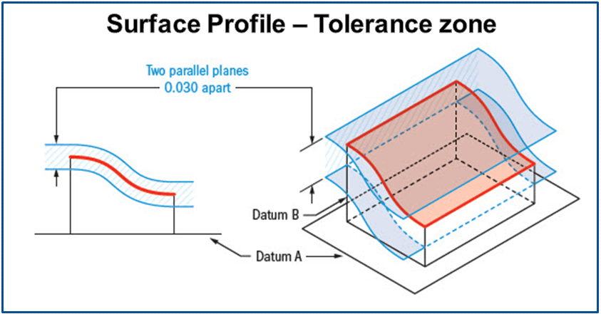
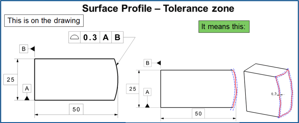
A feature control frame bearing the “surface profile” symbol specifies a 3-D tolerance zone having a total width equal to the tolerance value. The entire feature surface shall everywhere be contained within the tolerance zone. If a DRF is referenced, it restrains the orientation, or orientation and location of the tolerance zone.
Where the profile tolerance is equal-bilateral, the feature control frame is simply leader-directed to the profile outline, as in Fig. 7 (a).
Where the tolerance is unilateral or unequal-bilateral, dimension lines are drawn for the width of the tolerance zone, normal to the profile as in Fig. 7 (b) through (d). One end of a dimension line is extended to the feature control frame.

As depicted in Fig. 7, the profile tolerance zone is generated by offsetting each point on the basic profile in a direction normal to the basic profile at that point. This tolerance zone may be unilateral or bilateral relative to the basic profile.
For a unilateral profile tolerance, the basic profile is offset totally in one direction or the other by an amount equal to the profile tolerance. See Figs. 7-(c) and (d).
For a bilateral profile tolerance, the basic profile is offset in both directions by a combined amount equal to the profile tolerance. Equal offsets of half the tolerance in each direction—equal-bilateral tolerance—is the default. See Fig.7 (a). Though the offsets need not be equal, they shall be uniform everywhere along the basic profile.
Regardless of the tolerance zone’s disposition relative to the basic profile, it always represents the range of allowable variation for the feature. You could also think of this disposition as the basic profile running along one boundary of the tolerance band, or somewhere between the two boundaries. In any case, since the variations in most manufacturing processes tend to be equal/bidirectional, programmers typically program tool paths to target the mean of the tolerance zone. With an equal-bilateral tolerance, the basic profile runs right up the middle of the tolerance zone. That simplifies programming because the drawing’s basic dimensions directly define the mean tool path without any additional calculations. Programmers love equal-bilateral tolerances, the default. Of course, a unilateral tolerance is also acceptable. The drawing shall indicate the offset direction relative to the basic profile. Do this as shown in Fig.7 (c) and (d) by drawing a phantom line parallel to the basic profile on the tolerance zone side.
Draw the phantom line (or curve) only long enough to show clearly. The distance between the profile outline and the phantom line is up to the draftsman, but should be no more than necessary for visibility after copying (don’t forget photoreduction), and need not be related to the profile tolerance value. A pair of short phantom lines can likewise be drawn to indicate a bilateral tolerance zone with unequal distribution. See Fig. 6 (d). Draw one phantom line on each side of the profile outline with one visibly farther away to indicate the side having more offset. Then, show one basic dimension for the distance between the basic profile and one of the boundaries represented by a phantom line.
On complex and dense drawings, readers often fail to notice and comprehend such phantom lines, usually with disastrous consequences. Unequal-bilateral tolerancing is particularly confusing. If practicable, designers should spend a few extra minutes to convert the design for equal-bilateral tolerances. The designer will only have to make the computations once, precluding countless error-prone calculations down the road. If it is called out on a curved surface, like a fillet on a welded part, the entire surface where the radius is has to fall within the tolerance zone. Surface Profile controls all the points along the surface within a tolerance range that directly mimics the designed profile. Any point on the surface would not be able to vary inside or outside by more than the surface profile tolerance.
When is the surface Profile tolerance used?
Surface Profile is the catch-all symbol for surface control in GD&T. If it cannot be controlled with another symbol, profile is your best bet. When used with datums it can control every aspect of a feature’s geometry which includes size, location, orientation, and form. Profile of a surface can be used for advanced curved surfaces, such as when a surface curves in multiple axes at once. Commonly, casted parts call out surface profile when the surface is curved to control the amount of variation. Other uses could be an airplane wing, complex surfacing designs in automotive engineering, each requiring to fit between two parallel surfaces of the same shape to ensure the profiles are always consistent. Both profile of a line or profile of a surface can be called out on such surfaces, however, surface profile is more common.
Application of a surface profile tolerance works in the same way like Line Profile tolerance, is a three-step process:
- 1) define the basic profile,
- 2) define the tolerance zone disposition relative to the basic profile,
- 3) attach a profile feature control frame.
Tolerance zone is bilateral unless otherwise specified. it can be specified between two points or all-around using the same method for profile of a line between two points. Profile callout (feature control frame) is applied to a true profile on the drawing. The true profile is related to the datums reference with basic dimensions. Surface profile all around used for surfaces that have a constant, uniform cross-section shown on drawing by using the ‘ALL AROUND’ symbol on the leader connecting the feature control frame to the profile. Result is a tolerance zone consisting of two parallel boundaries equal in width to the tolerance. The tolerance zone should be perpendicular to a datum plane.
Example 1 . Curved surface
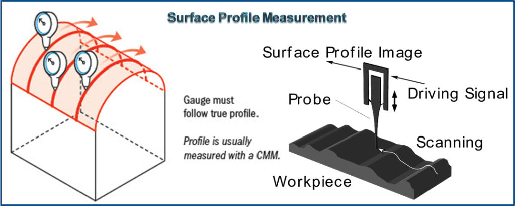
If you have a curved surface and want to ensure that every point falls within a specific tolerance range, you would call out a surface profile. This could be considered an advanced curve that could only be controlled with the use of a profile tolerance. The entire surface would have to be measured, usually with a CMM and then determined if the whole surface falls between the tolerance zones.
Note: Profile only controls the variance of the points in relationship to each other along the surface, similar to the flatness tolerance.

Example 2. Controlling the Extent of a Profile Tolerance
By default, a single profile tolerance applies to a single tangent-continuous profiled feature. There are cases where a feature’s tangency or continuity is interrupted, inconveniently dividing it into two or more features. We’d hate to plaster identical profile feature control frames all around a drawing view like playbills at a construction site. In other cases, different portions of a single feature should have different profile tolerances. An example is where only a portion of a feature is adjacent to a thin wall. Y14.5 provides three tools for expanding or limiting the extent of a profile tolerance: the “all around” symbol, the ALL OVER note, and the “between” symbol. These allow the designer very precise control of profiled features. In my explanations for them, I’ll be referring to the subject view—a single drawing view that shows a profile outline with a profile feature control frame. The “all around” symbol (a circle) modifies a profile tolerance to apply all around the entire outline shown in the subject view regardless of breaks in tangency.
As First Method – in Fig. 9 – I, the symbol is drawn at the “elbow” in the leader line from the feature control frame. “All around” control does not extend to surfaces or edges parallel to the viewing plane or to any feature not shown in the subject view. The note ALL OVER has not yet been replaced with a symbol.
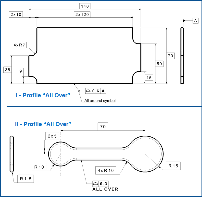
As Second Method – When the note appears below a profile feature control frame, as in Fig. 9-II, it modifies the profile tolerance to extend all over every surface of the part, including features or sections not shown in the subject view. (Any feature having its own specifications is exempt.) The few applications where this is appropriate include simple parts, castings, forgings, and truly 3-D profiled features. For example, we might specify an automobile door handle or the mold for a shampoo bottle with profile of a surface ALL OVER.
The 3rd method is to indicate (in the subject view) 2 points along the basic profile as terminations for the subject tolerance zone. Each point is designated by directing a reference letter to the point with a leader. See Fig. 10. If a terminating point is not located at an obvious break in the continuity or tangency of the basic profile, it shall be located with basic dimensions. In addition, the same two reference letters are repeated adjacent to the profile feature control frame, separated by the “between” symbol (a two-headed arrow). The tolerance applies along the basic profile only between the designated terminating points. Neither the choice of reference letters, their relative placement in the subject view, nor their sequence before or after the “between” symbol have any bearing on which portion of the feature is concerned. Where the profile outline closes upon itself, as in Fig. 10, the terminating points divide the outline into two portions, both of which can be interpreted as “between” the pair of points. The tolerance applies only to the portion having a leader from the feature control frame. A more complex profile outline having multiple feature control frames with more than two terminating points might require more care in clarifying the extents of the zones.

If, by using any of the above techniques, a profile tolerance is extended to include a sharp corner, the boundary lines for each adjacent surface are extended to intersect. In some designs, the intersection of the zones may not provide adequate control of the corner radius. A separate radius tolerance may be applied as a refinement of the profile control.
Example 3 – Abutting Zones
Abutting profile tolerance zones having boundaries with dissimilar offsets can impose weird or even impossible constraints on the surface. For example, if a zone unilaterally offset in one direction abuts a zone unilaterally offset in the other direction, the transition between zones has zero width. Where zones intersect at a corner, the surface radius could have concave, convex, and straight portions. A designer must carefully consider what the surface contour will be through the transition. Remember that manufacturing variation tends to be equal/bidirectional, and that tool path programmers target the mean of the tolerance zone. Thus, where the designer makes a narrow unilateral zone abut a much wider unilateral zone, the tool path within the wider zone is “programmer’s choice.” The programmer might choose to do one of the following.
- Keep the tool path consistently close to the basic profile, discarding tolerance in the wider zone.
- Make an abrupt step in the surface to always follow the median.
- Make a tapered transition to the median.
Since none of the choices are completely satisfactory, we have one more reason to try to use equal-bilateral tolerance zones.
Example 4. Profile Tolerance for Combinations of Characteristics
By skillfully manipulating tolerance values and datum references, an expert designer can use profile tolerancing to control a surface’s form, orientation, and/or location. That’s desirable where other types of tolerances, such as size limits, flatness, and angularity tolerances are inapplicable or awkward. For example, in Fig. 11, the profile tolerance controls the form of a conical taper. The reference to datum A additionally controls the cone’s orientation, and the reference to datum B controls the axial location of the cone relative to the end face. In this case, size limits are useless, but a single profile tolerance provides simple and elegant control. In other cases where more specialized controls will work just fine, it’s usually less confusing if the designer applies one or more of them instead.
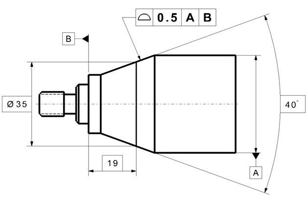
control a combination of characteristics
Example 5. – Single-Segment Feature Control Frame
Where feature “size,” form, orientation, location, and feature-to-feature spacing can all share a single tolerance value, a single-segment profile feature control frame is recommended. Fig. 12 shows a pattern of three mounting feet controlled for coplanarity. All points on all three feet shall be contained between a pair of parallel plane boundaries. This effectively controls the flatness of each foot as well as the coplanarity of all three together to prevent rocking. (A flatness tolerance would apply to each foot only on an individual basis.)

control coplanarity of three feet
Example 6 – Composite Feature Control Frame
A composite feature control frame can specify separate tolerances for overall pattern location and spacing. The composite profile feature control frame contains a single entry of the “surface profile” symbol. The upper segment establishes a Pattern Locating Tolerance Zone Framework (PLTZF) of wider profile tolerance zones that are basically located and oriented relative to the referenced datums. The lower segment provides a specialized refinement within the constraints of the upper segment. It establishes a Feature Relating Tolerance Zone Framework (FRTZF) of comparatively narrower zones that are basically oriented, but not located, relative to the referenced datums. For all these the Rules for Composite Control apply as follows:
Datum References—Since the lower segment provides specialized refinement only within the constraints of the upper segment, the lower segment may never reference any datum(s) that contradicts the DRF (Datum Reference Frame) of the upper segment. Neither shall there be any mismatch of material condition modifier symbols. This leaves 4 options for referencing datums in the lower segment.
- Reference no datums.
- Copy only the primary datum and its modifier (if any).
- Copy the primary and secondary datums and their modifiers, in order.
- Copy the primary, secondary, and tertiary datums and their modifiers, in order.
Only datums needed to restrain the orientation of the FRTZF may be referenced. The need for two datum references in a lower segment is somewhat rare, and for three, even more uncommon.

for a pattern
Tolerance Values—The upper-segment tolerance shall be greater than the lower-segment tolerance. Generally, the difference should be enough to make the added complexity worthwhile.
Simultaneous Requirements—The upper and lower segments may be verified separately, perhaps using two different functional gages. Thus, where both upper and lower segments reference a datum feature of size at MMC or at LMC, each segment may use a different datum derived from that datum
feature.
Optional Level 2 Control – For features of size such as holes, size limits or tolerances and Rule #1 specify Level 2 form control. For profiled features, each profile tolerance zone provides a degree of Level 2 control (for feature “size” and form). However, where no pattern-controlling tolerance provides adequate Level 2 control, a separate profile tolerance may be added above and separated from the pattern-controlling frame(s). In Fig. 13-II, the profile tolerance of 0.1 establishes a discrete profile tolerance zone for each individual feature. As with the Level 2 size limit boundaries for holes in a pattern, there is no basic relationship between these Level 2 profile zones. They are all free to float relative to each other and relative to any datums. (Note: If the Level 2 feature control frame were added as a third segment of the composite control, the Level 2 profile zones would be basically related to each other.) Of course, the Level 2 tolerance must be less than any pattern-controlling tolerances to have any effect.
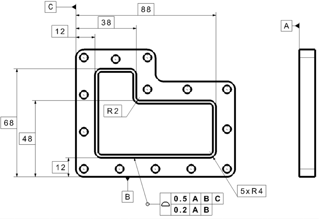
Example 7 – Composite Profile Tolerance for a Single Feature
For features of size, different characteristic symbols denote the 4 different levels of control. But, for irregularly shaped nonsize features, the same “profile of a surface” symbol is used for each level. In Fig. 14, for example, we want to refine a bounded feature’s orientation within the constraints of its locating tolerance. Simply stacking two single-segment profile feature control frames would be confusing. Many people would question whether the 0.2 tolerance controls location relative to datum B. Instead, we’ve borrowed from pattern control the composite feature control frame containing a single entry of the “surface profile” symbol. Though our “pattern” has only one feature, the tolerances mean the same. In Fig. 14, the upper segment establishes a 0.8 wide profile tolerance zone basically located and oriented relative to the DRF A|B|C. The lower segment provides a specialized refinement within the constraints of the upper segment. It establishes a 0.2 wide zone basically oriented, but not located, relative to the DRF A|B. All the rules given at the Example 6 above, governing datum references, tolerance values, and simultaneous requirements apply for a composite profile “pattern of one.”
Gauging/Measurement
Surface Profile is usually measured using a CMM due to the complexity of some of the surfaces that are called out. The CMM would compare the 3D scan of the profile to the dimensions called out on the drawing to see if it was in spec. If a simple surface is called out, such as a radius on a corner, a height gauge can be used to trace the part as long as the gauge can stay the same distance away from the surface as rotates around the surface. Surface Profile provides complete 3-D control of a feature’s total surface.
Relation to other GD & T Symbols
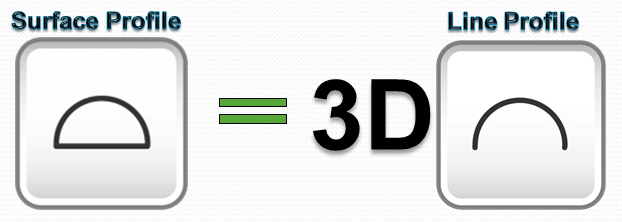
Profile of a surface is the 3D version of profile of a line. The difference between them is that profile of a surface would cover the entire required surface, making sure that every point falls in the tolerance zone, not just at a cross-section.
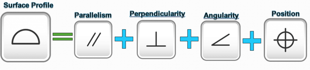
When used without datums, line profile can also be thought to be similar to flatness or cylindricity as these symbols are only more specific versions of the surface profile symbol. When used with datums, profile can mimic all the orientation symbols (perpendicularity, parallelism, angularity) and even control the location and size of a feature or surface. All of these tolerance symbols specify how much a surface of any geometric shape can vary from its true form. All of these symbols have a tolerance zone existing of parallel surfaces surrounding the measured profile.
Final Notes
Sometimes line profile is used in conjunction with surface profile. In these cases, the line profile tolerance will be tighter than the surface tolerance. This ensures that along any specific cross-section of the profile, the part will be tightly controlled, while at a looser extent, the total profile is also controlled.

Leave a comment