
Designing Helical Shapes such are Springs with variable pitches sometimes is a challenge, mainly for the beginners. But things are very simple to do & control, CREO Parametric is an excellent tool for that and in this post I will show you how to do such design work.
Step 1. Create New Part
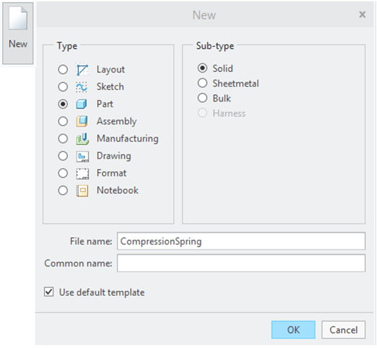
I click on New and I define a new regular part.
Step 2. Create the axis Sketch
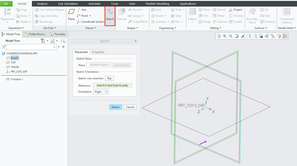
Like for any part before to build its shape you must define the necessary construction elements, a so called skeleton on which you add the rest of design features. For Springs this is in general a straight line which represents both the axis and the length of the spring. Therefore I start with this: in Model Workbench I click on Sketch icon and I choose a sketching plane.
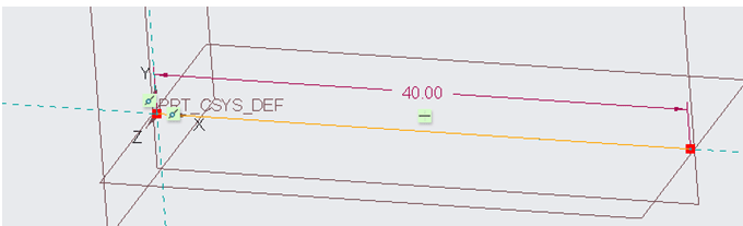
…I draw a line as shown and I click OK to exit the Sketch workbench.
Step 3. Create the Helical Sweep

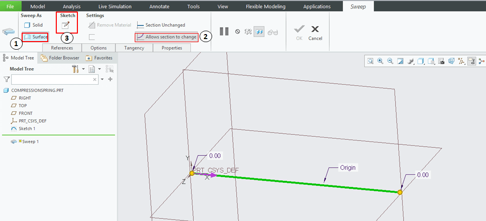
With the previously created sketch selected, I click on Sweep icon.
The Sweep Dialog box is now active and here I must define the parameters for the sweep. To understand how this works at first I do the parameters selection as shown:
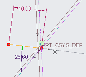
In Sketch Workbench I draw a line starting from the origin with a lenghts of 10mm which will automatically define the spring radius and an approximate angle close to 30° which defines how the line spins. I make only the length parameter as strong dimension, the angle I leave it as weak dimension and I click OK to exit the Sketch workbench.
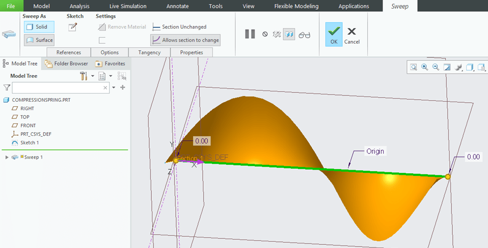
Back in Sweep dialog box I see this:
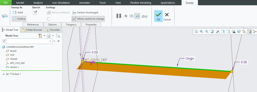
So as you can see the result is a very simple profile swept along the origin line. This is obviously not the shape of a compression spring. For this I must make the radius line spin around the origin line with a defined number of turns on the entire length.
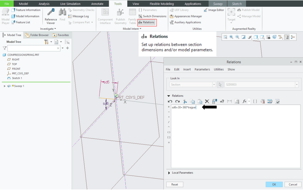
Therefore I don´t close yet the Sweep dialog box and I click again on Sketch option as I previously did. In Sketch workbench, I keep it like it is and I just switch on Tools Workbench where I must do a click on “Relations” icon. The Relations dialog box opens and as you can see the dimension values are now displayed with ID names. The reason why I said to leave the angle as weak dimension is because this angle is the variable parameter that I can control easier with a relation. For now I only want to show you how this definition works. In Relation dialog box I click on the Angle ID name and CREO will add it in Relations windows as the first item, then I must manually type the rest of the relation, so it must by written like this: sd6=30+360*trajpar
The items used in this relation mean this:
- Sd6 is the angle ID
- 30 represents the initial angle value
- 360 is the angle to be added after the initial 30°, but this angle I don´t want to add it immediately and for this reason I multiply it with a parameter called “trajpar” which is the trajectory parameter that turns the value of 0 to 1 in the length of the sweep.
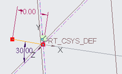
I click OK on the Relations dialog box to close it and as you now notice the angle value is displayed as 30° like defined in the relation.
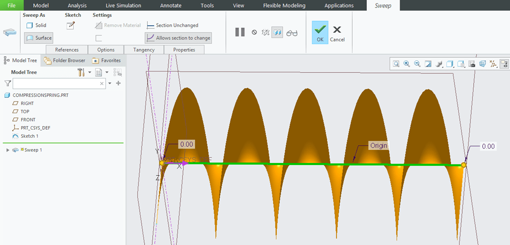
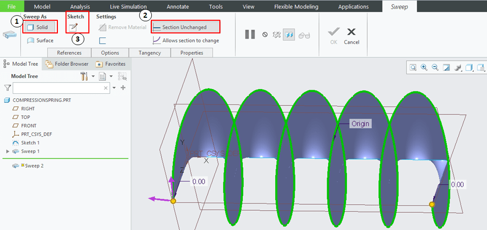
CREO activates back the Sweep dialog box and this time I see this:
This result is of course what I need to create the spring. Now let´s do the spring shape. I still stay in the Sweep dialog box, and I click again on Sketch option. I let the sketch workbench active and I switch again to Tools tab and I modify the text in Relations window. I don´t even need anymore the angle of 30°, (that was just to show you that you can start with angles but it´s totally ok if you put the line at 0°)
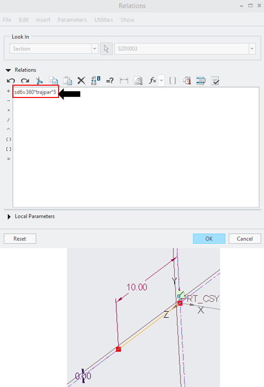
To make it easier I just modify the relation like this: sd6=360*trajpar*5 Where 5 represents the number of turns that I want for my spring. And I click OK. Note that the sketch now is just a straight line of 10mm long.
Now the result is obviously a contour that wraps around the origin line which is exactly a spring shape.
Step 4. Create the Spring Profile
The previously created Sweep is just a surface which helps me to create the solid spring. The necessary element here is the surface edge. So I pick this edge and I click on Sweep icon
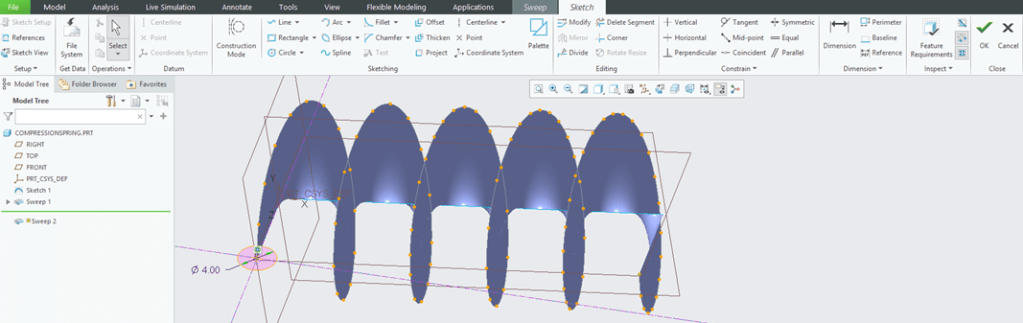
In the Sweep dialog box I must now define the sweep profile.
In the Sketch workbench, I can create any section I wish, but for a spring I create a circle of 4mm diameter with the center point coincident with the surface edge on its starting point and I click OK to exit.
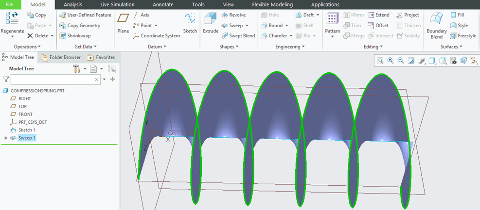
Back in Sweep preview the result is this:
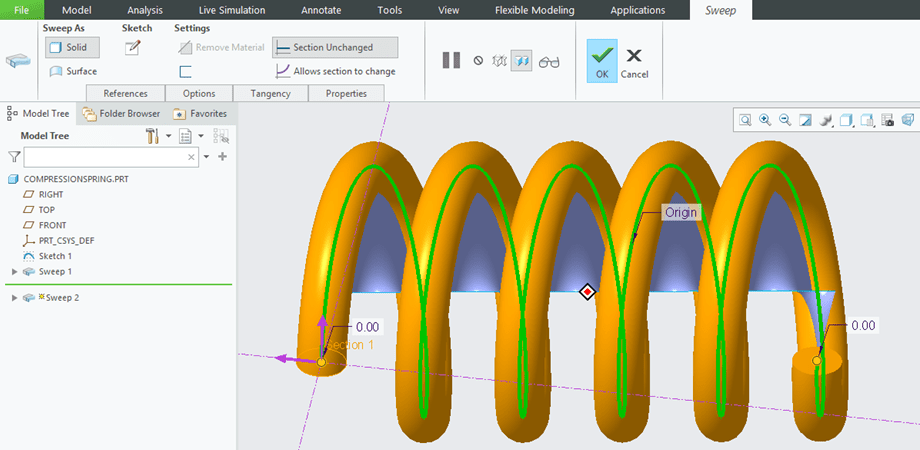
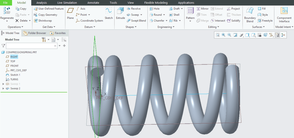
I click OK to exit, I hide the Surface Sweep and here it the spring:
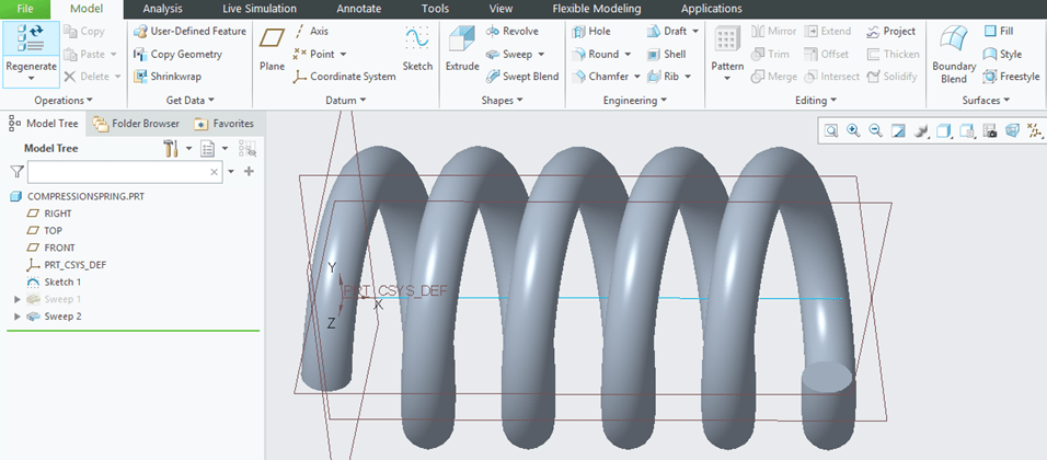
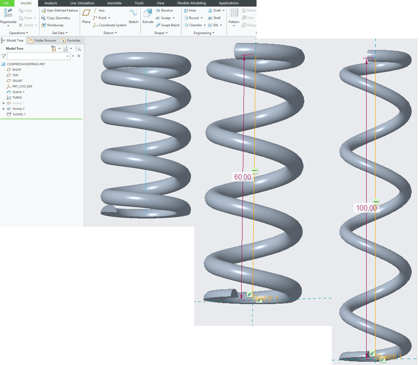
If I want a different length, I can easily change the value with a double click on the Origin line and modify the value. But the thing here is that the number or turns remains the same.
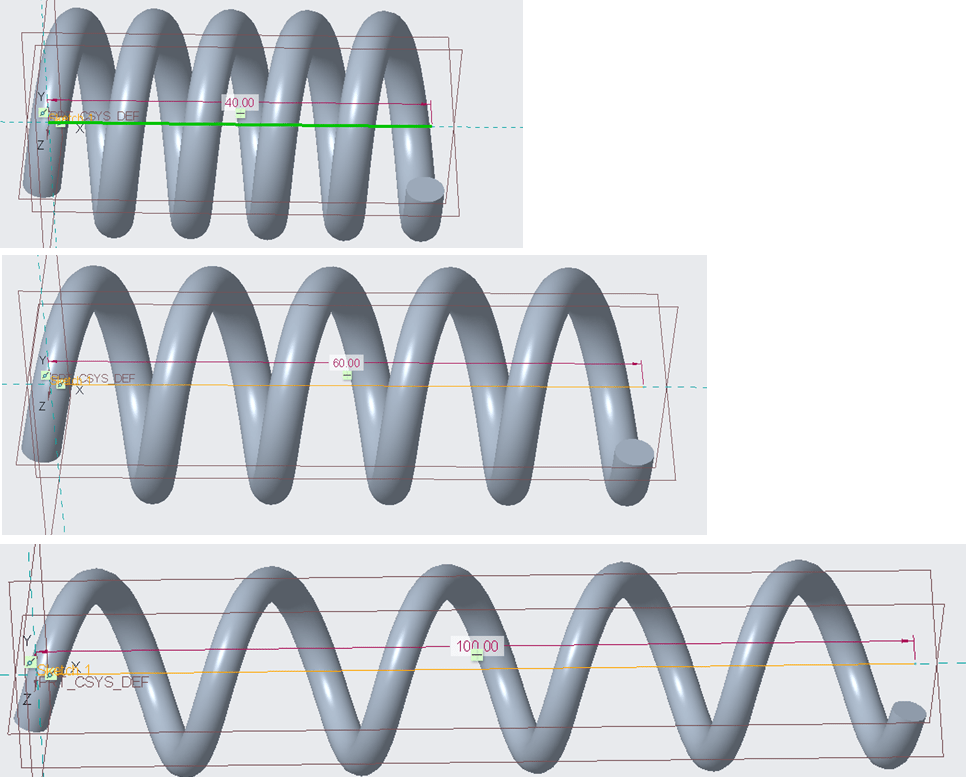
Step 5. Create a graphical relation
After the length change I can now change the number of turns instead of the pitch, but changing the pitch can be done with the Helical Sweep protrusion. But what if I want to vary the pitch?
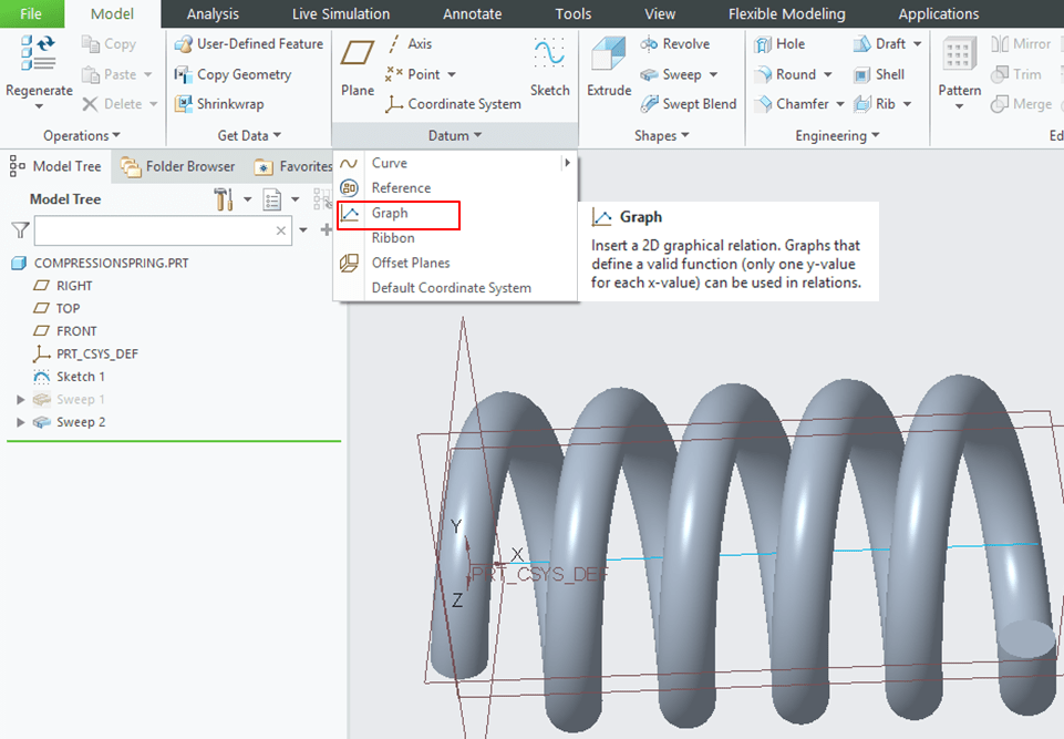
Well… CREO is very smart here, this is a very cool stuff. In Datum toolbar I click on the Graph option

I name it for example: Turns
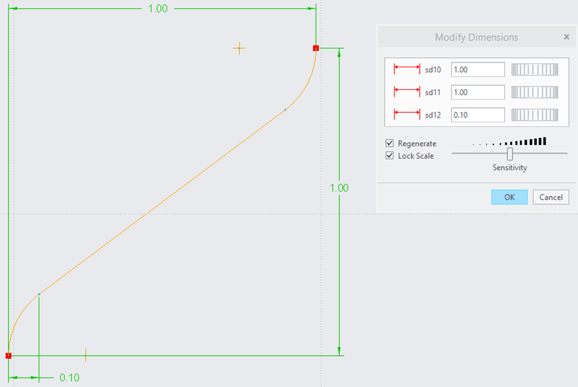
Now CREO is asking me to create a graph that I am going to use to control the turns. If I only draw a line as a slope, that will mean just a constant pitch and the number of turns will be determined by that slope. But if I want it to vary, then all I need to do is to change how this line behaves. For example I add on each line end an arc and I make both with the same radius. The I add a height dimension which will be the Y direction and a width which will be the X direction. Additionally I add another smaller dimension in X direction which will define how the pitch will change on that length portion. Then I select all dimension values and modify them. I tick the Lock Scale option because I want the dimensions to be unitized and I type the dimension as shown.
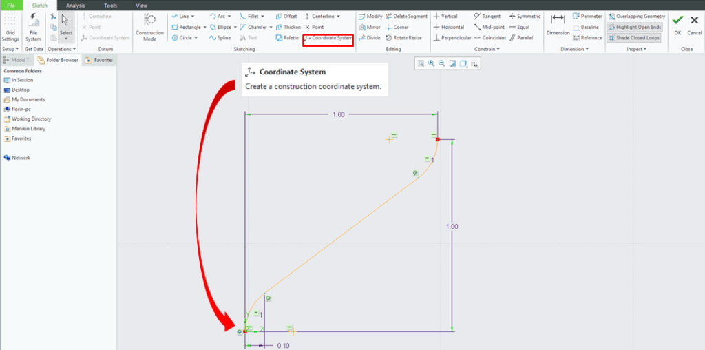
Before to finish the graph feature, the last requirement that CREO wants is to create a Construction coordinate system telling CREO where I want the point 0,0,0 to be. So I click on the Coordinate System icon and I place it on the bottom point of the sketch and I click OK to exit the graph definition.
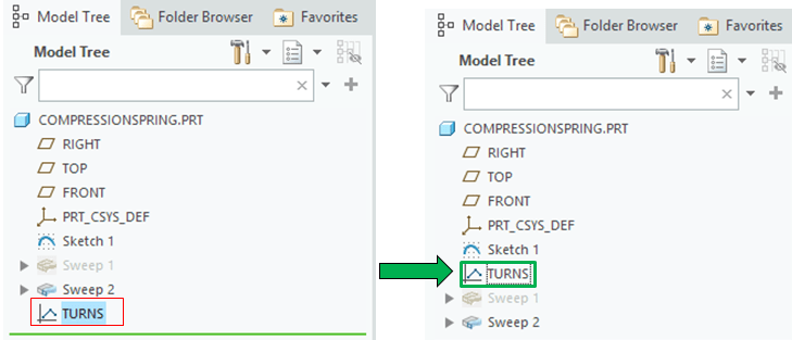
Now I´ve got a graph feature that I can use for my helical sweep. Therefore I drag this before all the sweep features so that I can use it in its derivation.
Step 6. Use the graphical relation for spring definition
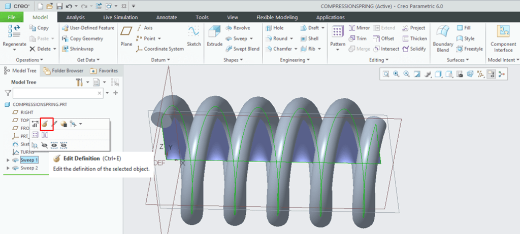
Now I unhide the surface sweep , I go back to its definition
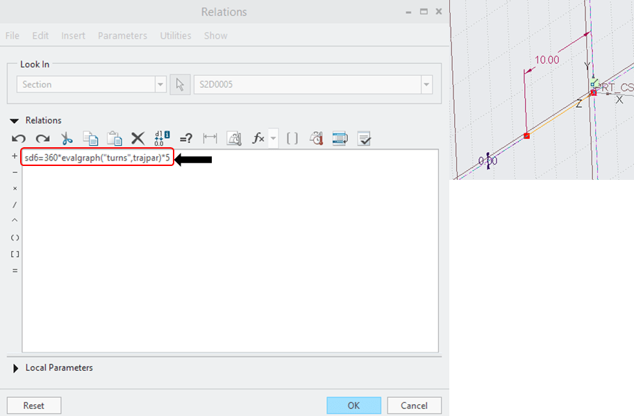
And again in its sketch. I go to Tools tab, I click on Relations icon and I modify the parameters telling CREO to evaluate the Graph. For that CREO requires a term called “evalgraph” and also I must specify in parenthesis and quotes the name of the graph folowed by the item called trajpar. The full line becomes now: sd6=360*evalgraph(“turns”,trajpar)*5
Be careful with the spelling and the type of characters you use, in case something is wrongly typed CREO will tell you to correct the relation before to continue.
If I call this done, now in the Sweep dialog box I notice that the Helical Shape has both ends compressed.
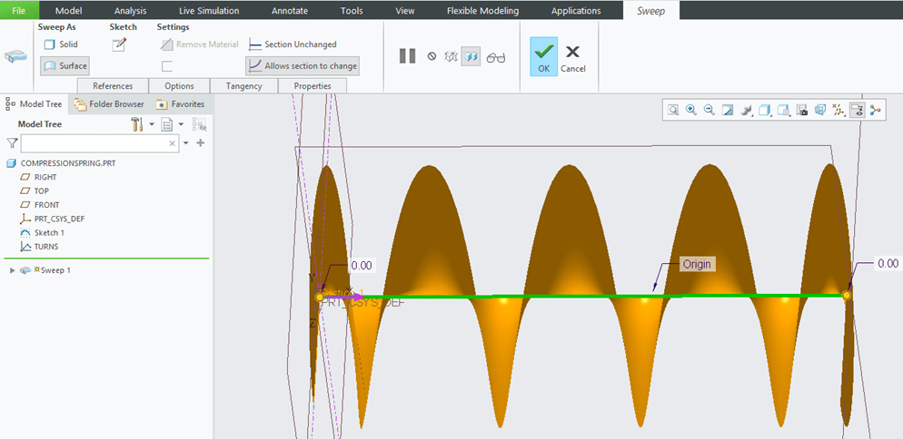
I click Ok on that and the result is this:

But because I want the entire protrusion to reflect this change I go back to its definition. By holding the Shift Key down, I right click on the edge until I get all my tangent and done. Then I click Ok to exit the Sweep dialog box.
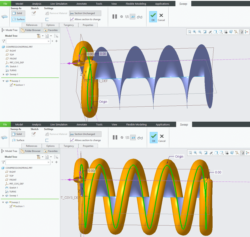
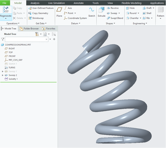
I hide the Surface Sweep and this is my spring design.
Step 7. Spring Dress-Up
One last adjustment for example if I want to ground the ends I can simply cut the spring like shown. I pick a plane, I click on Solidify icon, I check the side to be removed and I click ok.
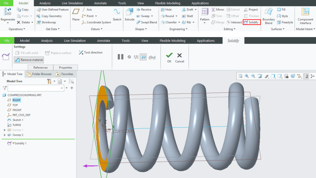
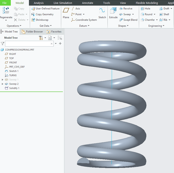
Like this the spring will always have a grounded end, no matter if I decide to change the spring length.
As you can see the ends will always stay compressed with the 0.1mm value as defined in the Graph feature.
Step 8. Change the Spring Shape
If for example I change my mind and I want my spring to be wrapped around an arbitrary shape, all what I need to do is to change the Origin sketch. For example instead of a line I want an arc.
I edit this origin Sketch, I draw an arc, then I click on the line and from the pop-up menu I click on Replace, Then I click on the arc I have just drawn. If the previous straight line had dimension on it CREO will tell me to delete that before to Replace the Entity. I click Yes and afterwards I can put the new dimension on my arc and I click OK to exit the sketch.

My Spring is now wrapped around the new sketch. It looks like this:
This exercise is also available as video version on my YouTube Channel as shown below:

Leave a comment