
CREO Parametric it is indeed very Parametric CAD platform. Designing with CREO is super effective, it´s a pleasure to work with it, I love this software. It´s powerful, it´s fun, it´s user friendly and you can use it in any type of mechanical design projects. In this post I want to show you an example of how Helical Sweep works and how Surface Design Mode can easily be combined with Solid Design Mode to create a complex shape part such as the Extrusion Screw. Follow the steps as described below and you will get a better understanding about how all that works.
Step 1: Create New Part
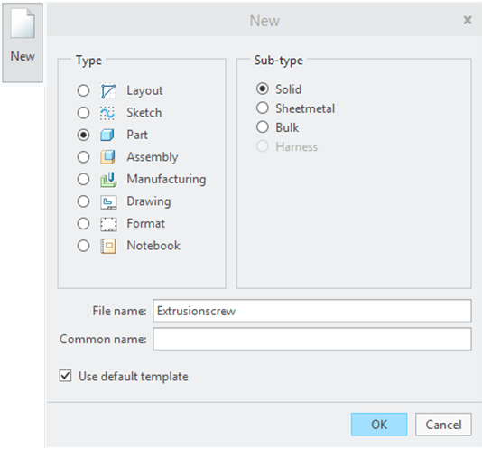
Click on New and create a new part as shown.
To create an extrusion screw first you need some construction features which will help you during the design process. Your work starts with features created in Surface Mode and after the main body is fully defined with the necessary surfaces you will continue with the design steps adding volume to your part and the final dress-up features as solid features. So let´s play with surfaces first.
As this is a circular part, obviously the 1st feature to be created is a Revolve which will be the reference for the rest. Extrusion Screws are used in many applications, they can be either Cylindrical or Conical, with constant or with variable pitch. From my experience in injection molding technology, I always recommend the Conical shapes with variable pitch. This is the best design for a performant injection molding process of plastic parts.
The 1st feature to be created is the conical Outer Surface – which will define the size of your screw and then The second is the conical Inner Surface – which will be the reference for the helical sweep which creates the shape of the Extrusion Screw.
Step 2: Create the Conical Outer Surface
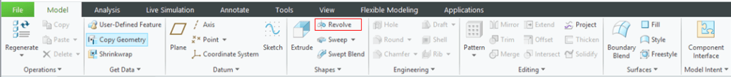
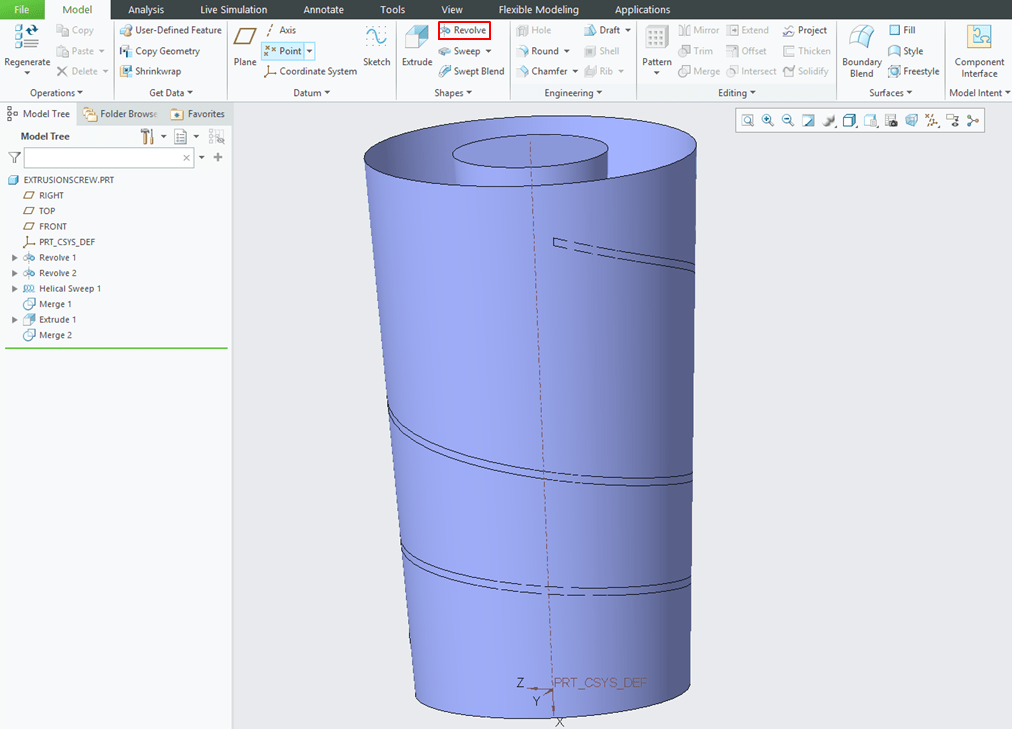
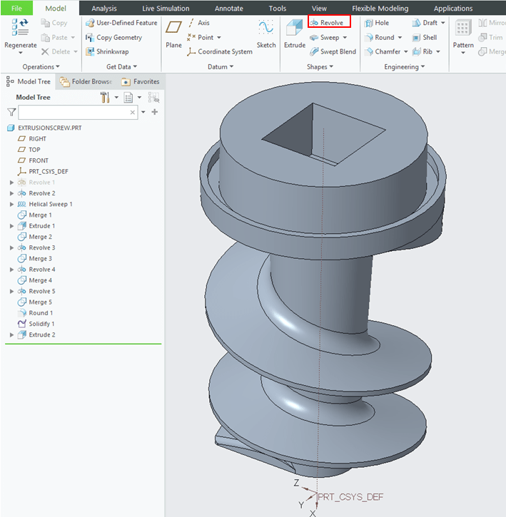
After you created the New Part , Creo put you directly in Model Workbench. Start with a click on Revolve Icon
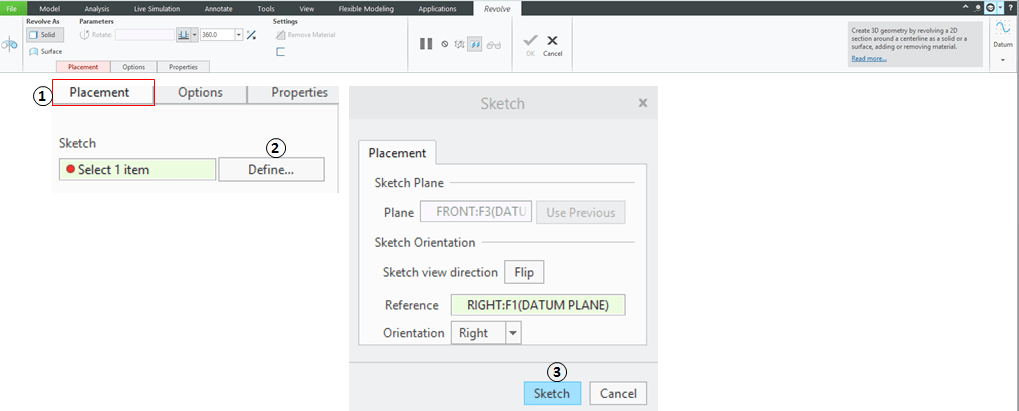
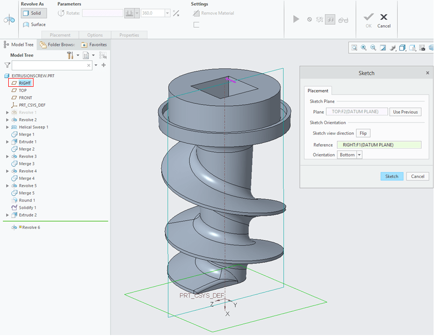
In the Revolve dialog box , Click on Placement and Select the sketch plane.
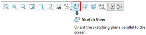
It usually happens that the sketch view is not always oriented perpendicularly to the screen, click the icon to align it accordingly.
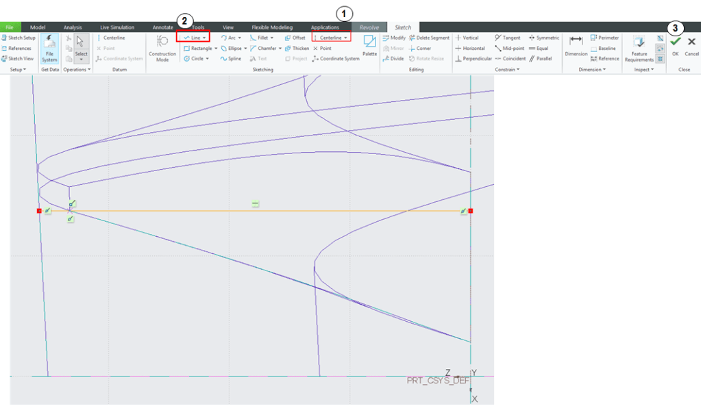
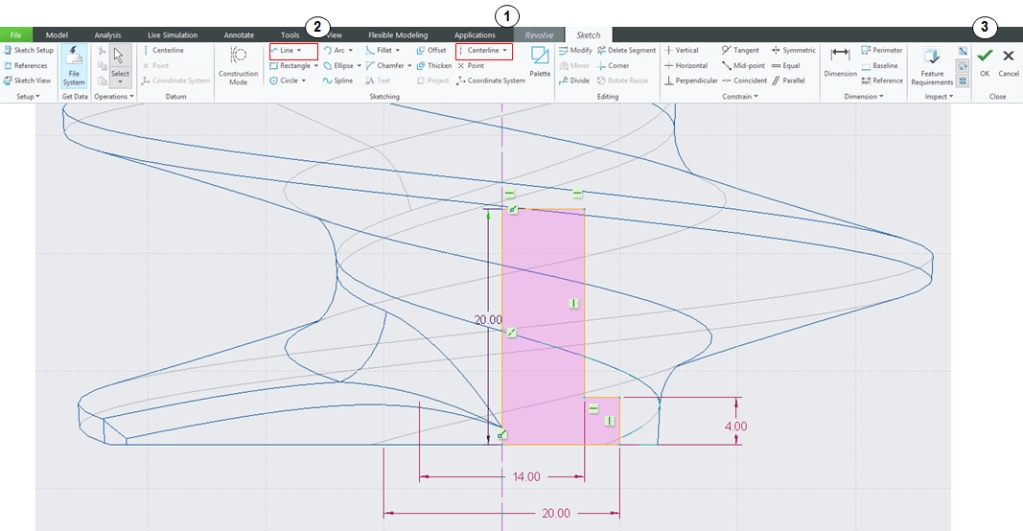
Then draw the sketch profile as shown.

The setting nr.3 is just to quick check if everything is ok with the sketch- but for simple lines like this here, not really necessary to use it but is good to have some practice anyway. Click OK and Creo will put you back in Revolve definition dialog box. Like I mentioned at the beginning, before to add volume to your part you first must work with surfaces. Therefore keep the setting “Revolve As Surface” selected and click OK.

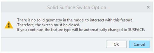
Whenever you sketch an open profile in case you have forgotten to select Revolve as Surface, CREO will immediately inform you that the feature you are about to create will be automatically changed to Surface, so if you see this message, no worries, just click OK and continue your work.
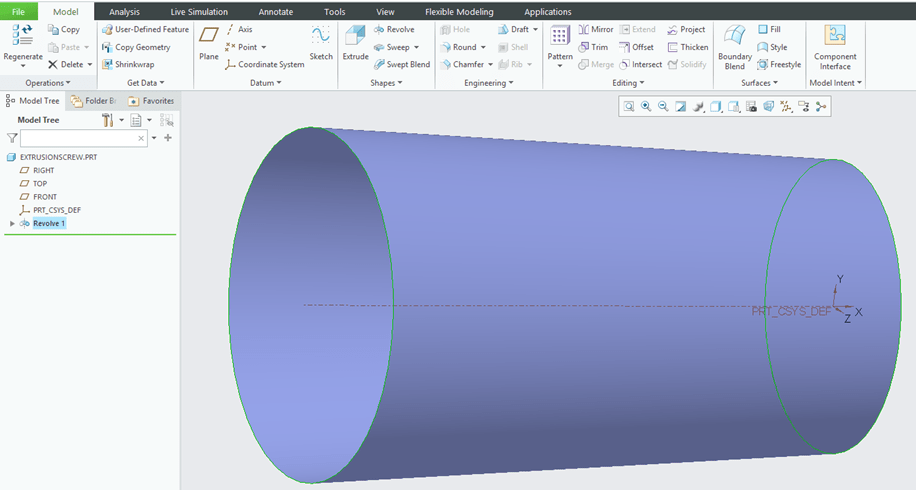
The Outer Surface is created and Revolve feature added in the Model Tree
Step 3: Create the Conical Inner Surface
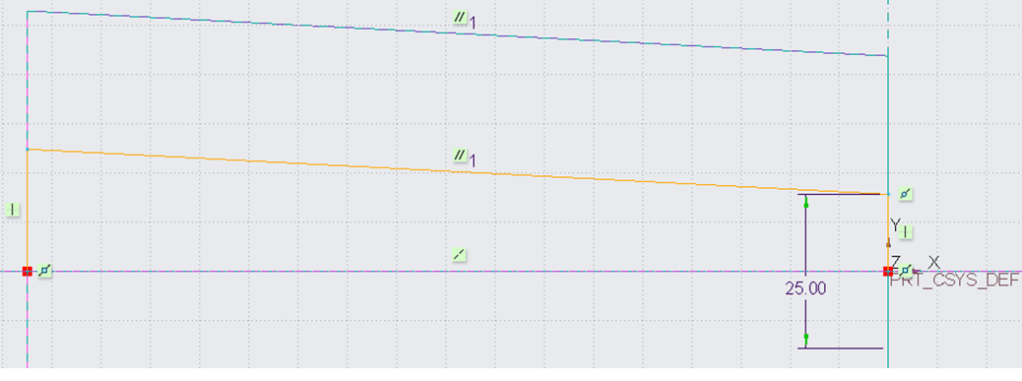
Create the 2nd Revolve in a similar way like you have just did. Draw the sketch as shown:
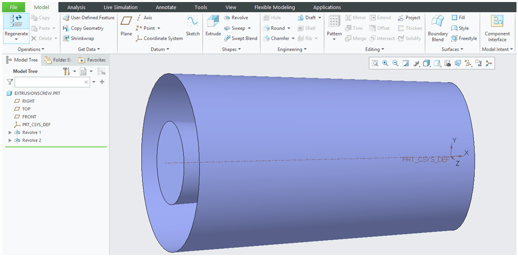
The 2 construction surfaces are now available and both features are added in the Model Tree.
Step 4: Create the Helical Sweep
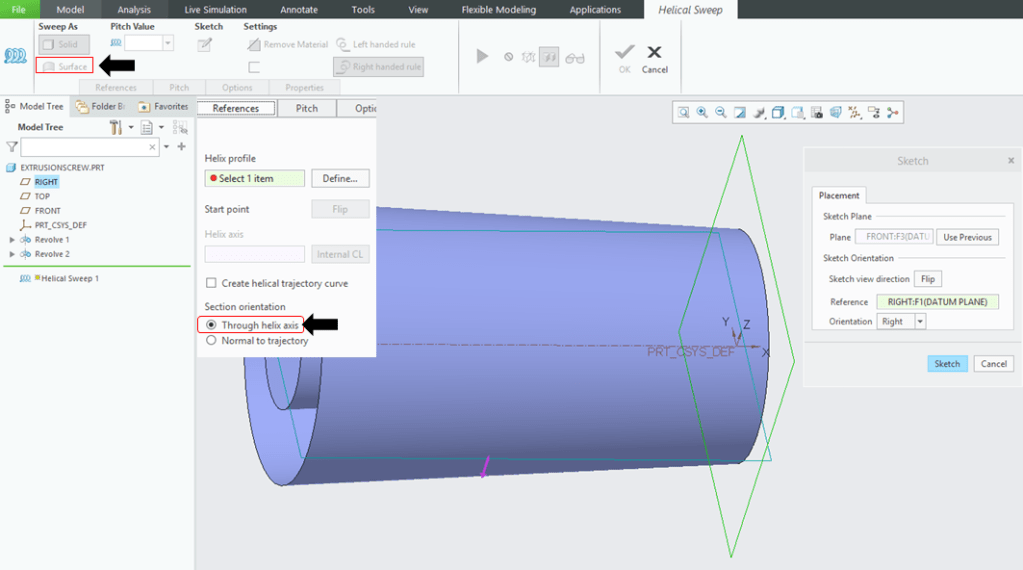
In Model Display Mode click on Helical Sweep icon.

In the Helical Sweep dialog box keep the “Sweep As Surface” option selected and go ahead with sketch definition.
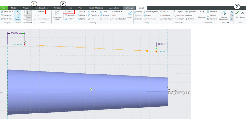
In “Sketch” workbench define a line as shown, and click Ok to exit the Sketch.
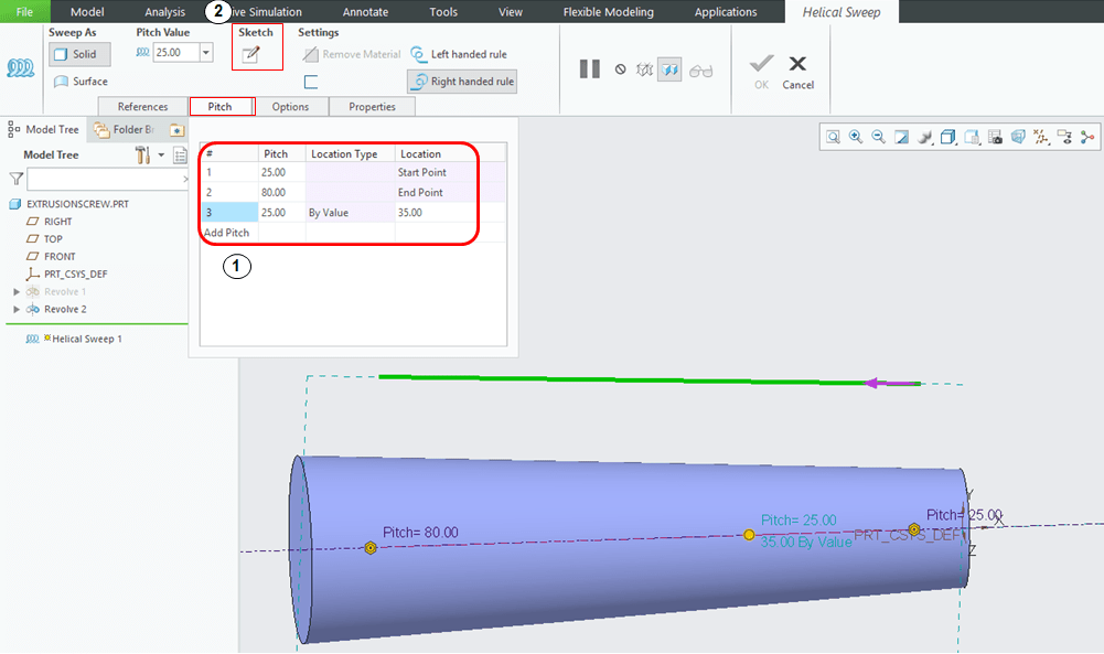
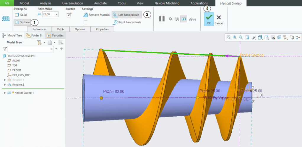
Back in “Helical Sweep” dialog box (1) do the necessary settings in the Pitch tab with the values as shown and then (2) click on Sketch icon.
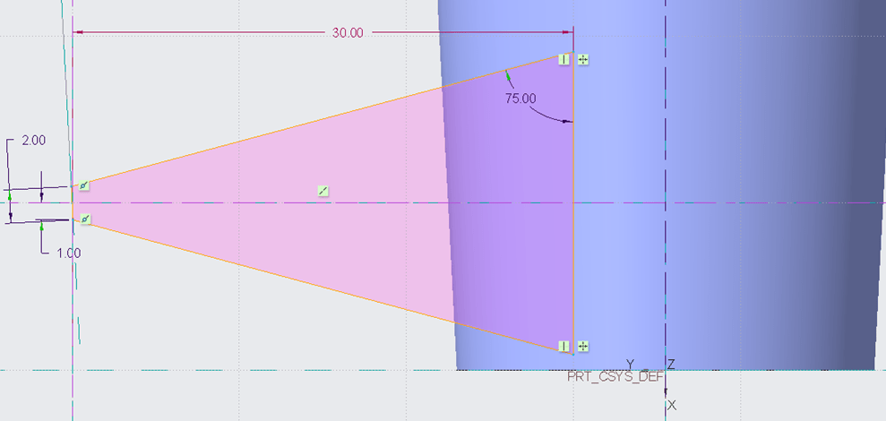
In this Sketch define the profile as shown – note that the left side small line is not vertical but coincident with the Conical Outer Surface line, therefore a little bit tilted. Then click OK to exit the Sketch workbench.
Back again in the Helical Sweep dialog box do the last settings, eventually try to preview the shape and then click OK to exit this dialog box.
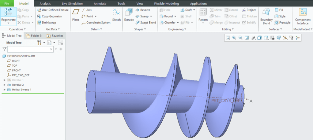
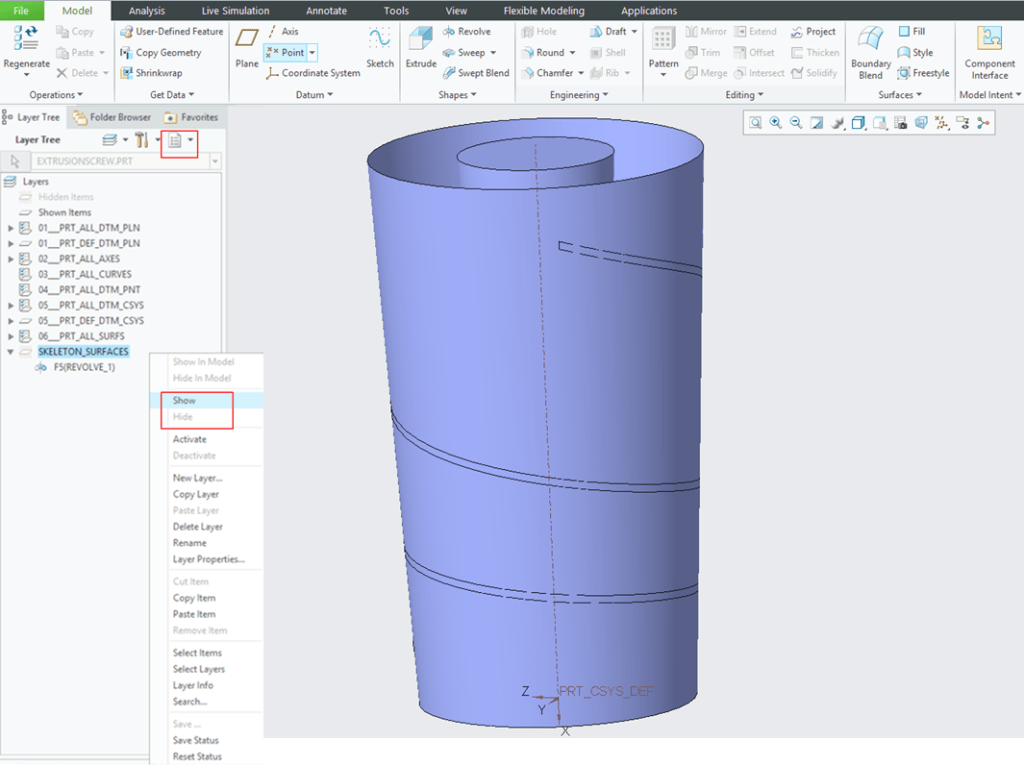
Creo will put you back in Model Workbench, showing you all the surfaces you have created so far. Here you already have the main features necessary to define your Extrusion Screw design. In order to improve the visibility in many cases some construction features are not really necessary to be displayed therefore during the design work is easier to have a smooth design process if these construction features once defined are kept hidden and you can only show them again if necessary. It´s the case here with the Conical Outer Surface. You can simply Right click on “Revolve 1” feature in Model Tree on the left side of the screen and from the displayed menu choose the option ” Hide”. This is the basic and fastest way to hide/show a feature in CREO.
But oftentimes, more than multiple features must behave in a similar way, and for example to hide and show them instantly instead of activation hide and show for each one is very useful to organize these features in different layers. Actually CREO has already some layers defined by default but you can always add, delete or modify any of these layers. So for the scope of doing an exercise the Layer Definition in CREO goes as follows:
Step 5: Working with Layers
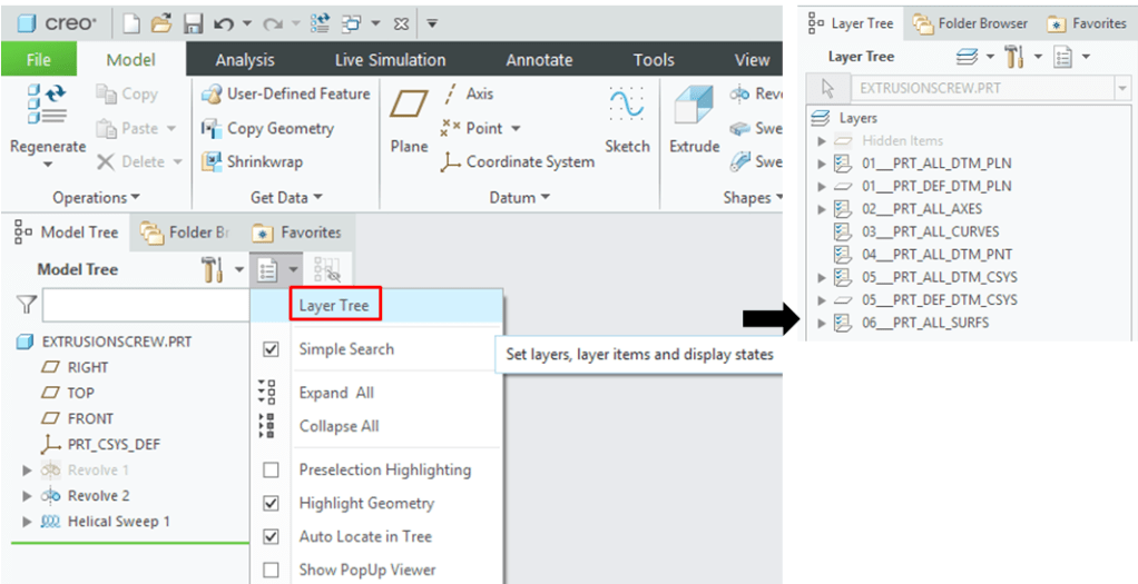
In the Model Tree tab click on the 2nd Icon and from the drop-down menu click on “Layer Tree” option. CREO will show you all the Layers currently available for your Part Design.
Right click on a free space inside the Layer Tree window on the left side of the screen and from the drop-down menu (1) choose “New Layer…” option. , (2) Name it, (3) Click inside the Content tab window and Click on the Conical Outer Surface a.k.a Revolve 1 feature. then (4) click ok to close the layer Properties dialog box. The Conical Outer Surface is now included in this new Layer.

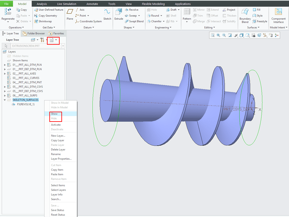
This is how layers work in CREO. In this way whenever you what to show or hide a group of features from the same layer just right click on the Layer name and from the drop-down menu click on Show or Hide Mode according to your design need.
Step 6: Create the 1st Merged Surface.
Back in Model Tree display, keep the last 2 features selected (Revolve 2 + Helical Sweep) and Click on the Merge Icon.

In the Merge dialog box adjust the merging direction by changing the direction shown by the arrows so that the result will look like shown on the right side in the screenshot below, then Click Ok to exit the dialog box.
Step 7: Cut the excess of helical surface on the bottom side.
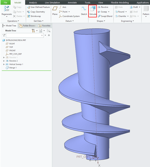
In Model display mode click on the “Extrude” icon
In Extrude dialog box keep the Surface Mode option selected and define the necessary sketch by drawing a line on lower side as shown below and then click Ok to exit the Sketch Workbench.
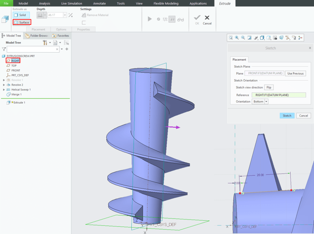
Back in Extrude dialog box check one more time if the result is the expected one, if necessary do the correction and then click OK to exit the Extrude dialog box.

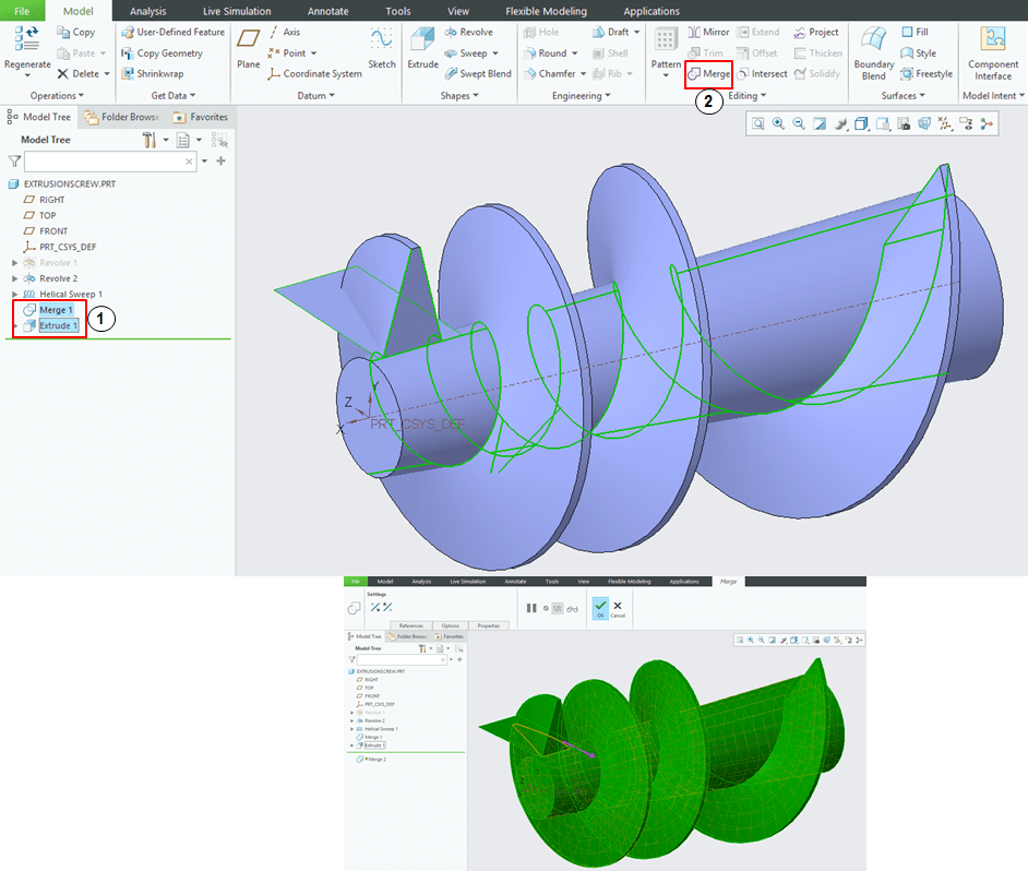
Step 8: Create the 2nd Merged Surface
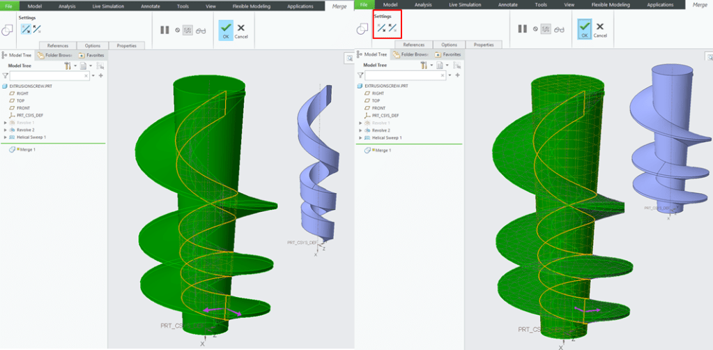
In Model Display Mode keep the last 2 feature selected and click on Merge Icon, then inside the Merge Dialog box check for the right merging direction and then click OK.

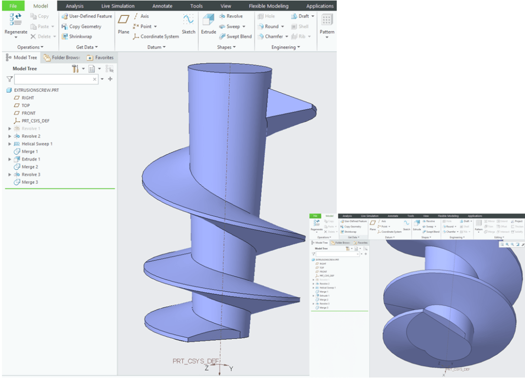
At this stage your design should look like this.
For the next design steps you will need to work with the Conical Outer Surface in order to define the final part design features. So you must hide and show couple of times the Revolve.1 feature as previously included in the New Layer. So before to continue, switch to Layer Tree mode, right click in the last Layer you´ve created and click on Show option in the drop-down menu. Then Switch back to Model Tree Mode.
Step 9: Cut the bottom side of the Extrusion Screw
To do this , in the Model Display Mode create another Revolve feature.
In the sketch mode define a line as shown and click OK to exit the Sketch Workbench.
In the Revolve Dialog box, check if all the settings yield the expected result, do the corrections if necessary and click OK to exit this dialog box.
Step 10: Merge the bottom side surfaces.
In the Model Tree on the left side of the CREO screen Keep the last 2 features selected and click on Merge icon.

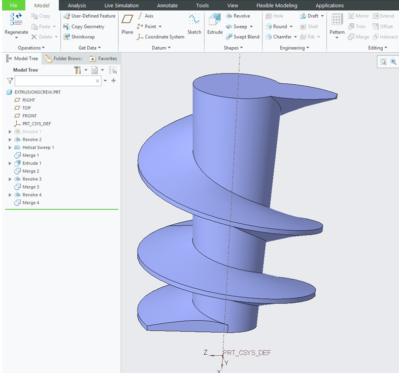
At this stage your design should look like this.
Step 11: Merge the top side surfaces.
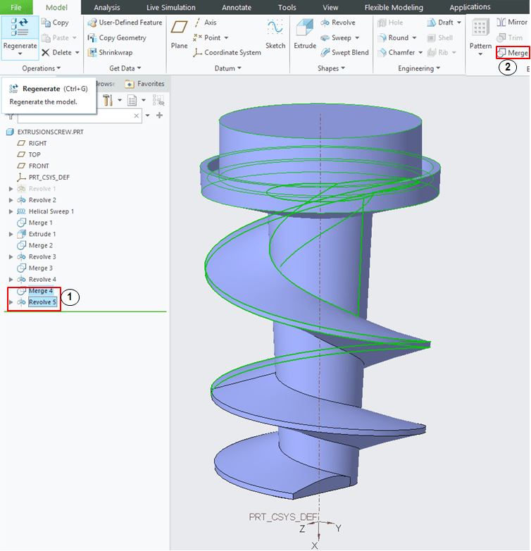
Similar with Step 10, create another Revolute surface defined by the line sketched as shown below.

After this cut your part should look like this.
Step 12: Create the top side design.
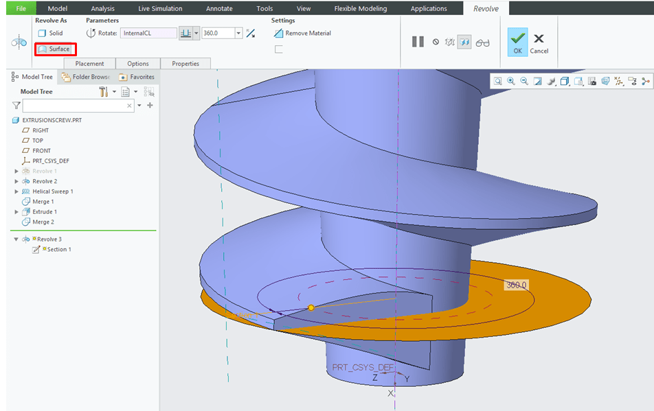
On the top side of your extrusion screw you want to design the part in such a way that it can be fixed in a clamping head of drilling machine. In the Model Display mode click on Revolute icon and define the top profile as shown below. Then click OK to exit the Sketch Workbench.
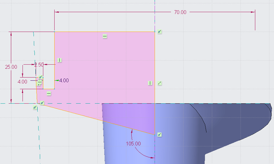
Back in Revolve dialog box, check if all the design parameters yield the right result, do the corrections if necessary and click Ok to exit the Revolute dialog box.

Step 13: Merge the top side surfaces.
In the Model Tree on the left side of the CREO screen, keep the last 2 features selected and click on Merge Icon.
In the Merge dialog box check if the merging directions generate the correct result, do the corrections if necessary and click OK.

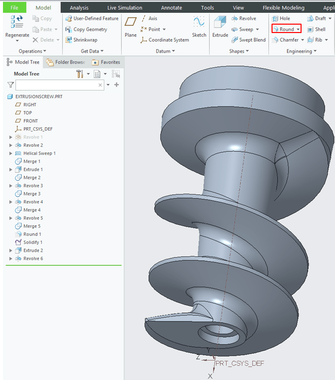
Step 14: Add the dress up Rounds.
In Model Display mode click on Round icon.
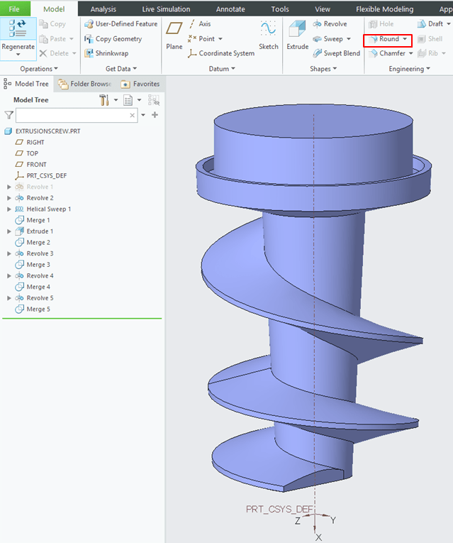
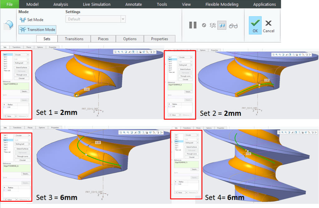
Rounds can be either created in individual feature one after another having different values or they can be created in the one single feature all together but defined in sets with different values. For this design exercise the best way to put rounds on your part is to create them in one single feature in 7 sets each with its own dimension value. Therefore proceed as shown below:
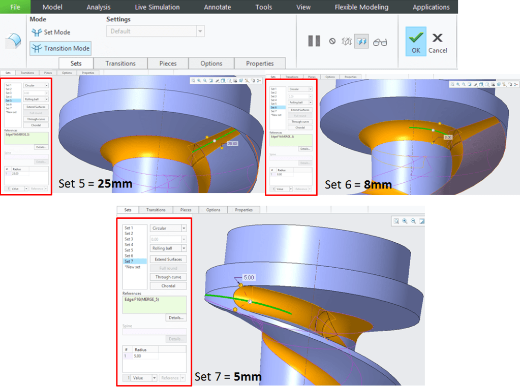
After you´ve finished introducing all the dimension values, before to click OK in order to exit the dialog box, you can also try to put everything in Transition Mode, this can sometimes give you a better result. Then just click OK to exit the Round dialog box.
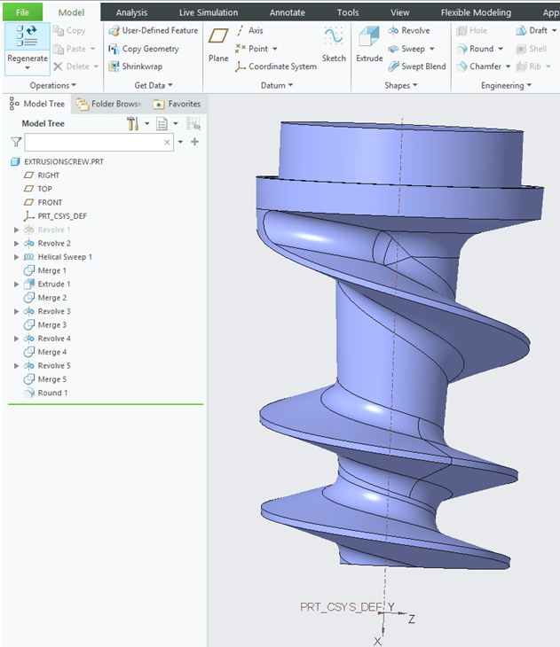
Your design in Surface Mode at this stage should look like this:
Step 15: Adding volume.
Until now all the previous design steps you did were in Surface Mode. Now after all the surfaces are ready, it´s time to add volume to your part. Therefore for the next design steps all the features you add are done in Solid Mode. But first you must Solidify your part. To do this is very simple, just keep the last feature in Model Tree selected ( Round.1) and click in Solidify icon.

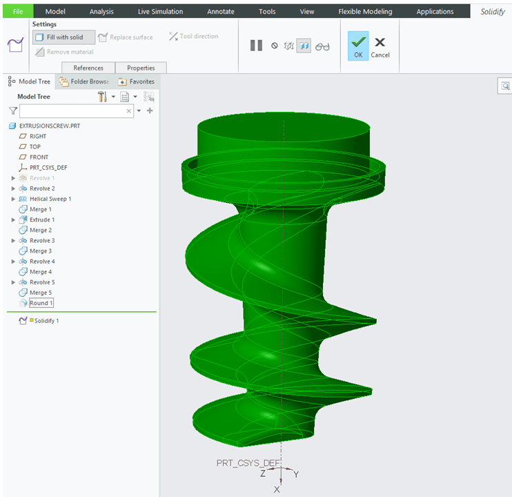
In Solidify dialog box only check the result and click OK.
Step 16: Create the top side design
For a simplified design version just add a new extrude which will become a fixation pocket on the top side of the extrusion screw.
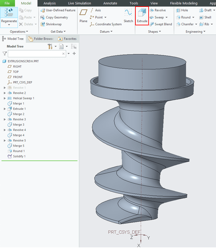
To do this, In Model Display mode click on Extrude icon.
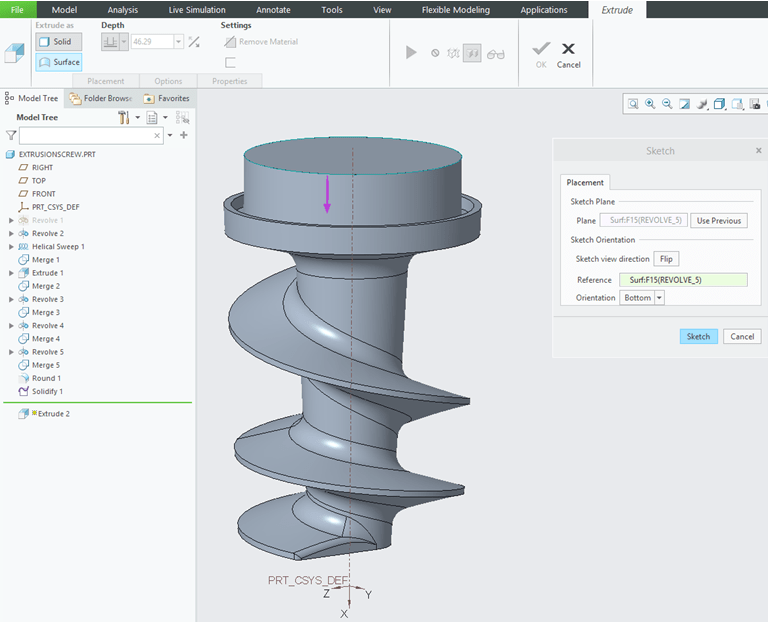
In the Extrude dialog box define the sketch plane as the top surface of the screw and click the Sketch button.
This time you can try something different than usual sketching. Because you only need a square, no need to draw it completely, you can just pick one from the CREO library. To do this from Sketching tools click on Palette icon. The Sketcher Palette will be open. Click the 4 Sided square and drag it on your sketch view. Make it coincident with the circle center of top surface and type 30mm as single dimension. Then click OK to exit the sketch Workbench.

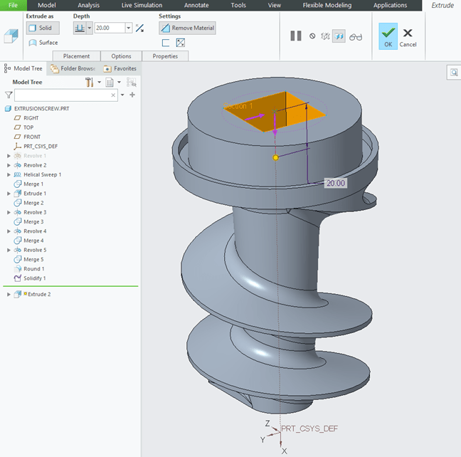
Back in Extrude dialog box in case the extrude direction is oriented outwards, click on the direction arrow to make it inwards. Then click OK to exit the dialog box.
Step 17: Create the bottom side design.
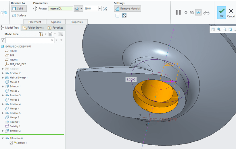
For the bottom side you can add for example a Revolute feature. So, in the Model display mode click on Revolute icon.
In the Revolute dialog box define the sketch plane as shown:
And in Sketch workbench define the following profile and then click OK to exit the sketch workbench.
Back in Revolute dialog box do the final checking, do the corrections if necessary and click OK to exit.
Step 18: Add the Round on inner surface edge.
In Model Display Mode click on Round icon.
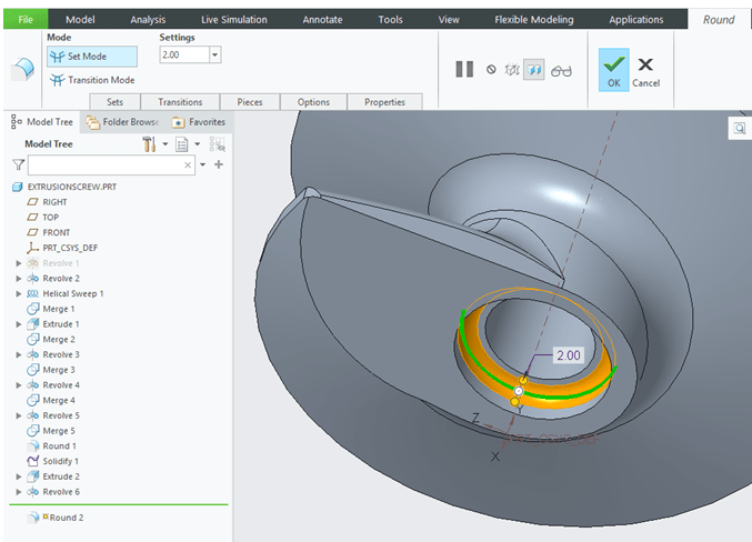
In the Round dialog box select the inner edge, define its value at 2mm and click OK to exit the dialog box.
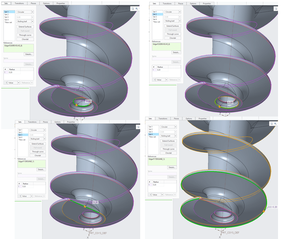
Step 19: Add the final Rounds
This step is similar with Step 14, the only difference here is that all the selected edges have the same rounds values. Put 0.2mm everywhere and click OK to exit the dialog box.
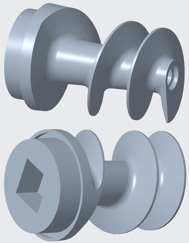
Extrusion Screw Design DONE. Your part should look like this.
This exercise is also available as video version on my YouTube Channel as shown below:

Leave a comment