In a mechanical design of an assembly made up of various parts it is often the case to make sure the functional elements are perpendicular to a reference. In GD & T this is called Perpendicularity Tolerance.
Like parallelism, the perpendicularity tolerance is also an Orientation tolerance from the sub-group of Direction tolerances. Therefore for every object made of assembled parts, in order to have a functional product it is essential to understand how this type of specification works.
The perpendicularity of surfaces, edges and lines is one of the geometrical basics of mass production. The perpendicularity of many functionally important surfaces for example of reference surfaces, must be localized accordingly. I wish to mention that all the rules applied for Parallelism (see my article about Parallelism, too) are also valid for Perpendicularity, with the only difference that the angle between the datum and tolerated element must be exactly 90°.
Special Note:
Perpendicularity in GD&T can mean two very different things depending on which reference feature is called out.
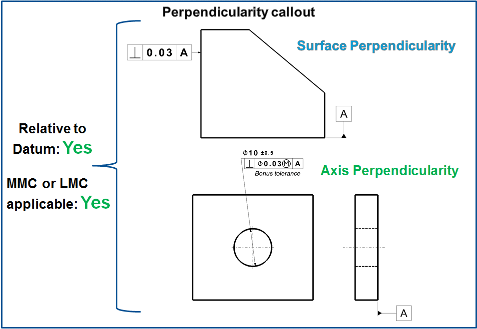
The normal form or Surface Perpendicularity is a tolerance that controls Perpendicularity between two 90° surfaces, or features. Surface Perpendicularity is controlled with two parallel planes acting as its tolerance zone.
Axis Perpendicularity is a tolerance that controls how perpendicular a specific axis needs to be to a datum. Axis Perpendicularity is controlled by a cylinder around a theoretical perfectly parallel axis.
Pay close attention if a hole or pin is referenced since axis perpendicularity is commonly called out on these features.
Description
As a general description the Perpendicularity tolerance is a 3-dimensional geometric tolerance that controls how much a surface, axis, or plane can deviate from a 90 degree angle or it is can be defined as a condition of a surface, median plant, or axis at 90 degree to a datum plane or axis.
But because this type of tolerance applies a bit differently on Surfaces and Axis, I would say that for both cases there is a specific tolerance description as follows:
Surface: Perpendicularity is a fairly common symbol that requires the referenced surface or line to be perpendicular or 90° from a datum surface or line. Perpendicularity can reference a 2D line, but more commonly it describes the orientation of one surface plane perpendicular to another datum plane. The tolerance of the perpendicularity callout indirectly controls the 90° angle between the parts by controlling the location where the surfaces have to lie. See the tolerance zone below for more details.
Note: Perpendicularity does not control the angle of the referenced feature –the tolerance is in distance units. (mm/in)
Axis: Axis control can also be called out for Perpendicularity and is one of the more common forms of axes call outs. When it is referenced for a circular feature, the feature control frame will contain the diameter (Ø) symbol. Axis Perpendicularity can be applied to a positive feature (pin/boss) or to a negative feature (a hole). When Perpendicularity is referenced for axial control of a feature, the symbol now specifies a cylindrical boundary where the axis of the referenced feature must lie. This cylindrical boundary is formed by taking a line that is directly perpendicular to the datum feature. When this version of Perpendicularity is called out it is to be used with Maximum Material Condition to enable easy gauging of the part. See example 1 below for how these particular parts are gauged.
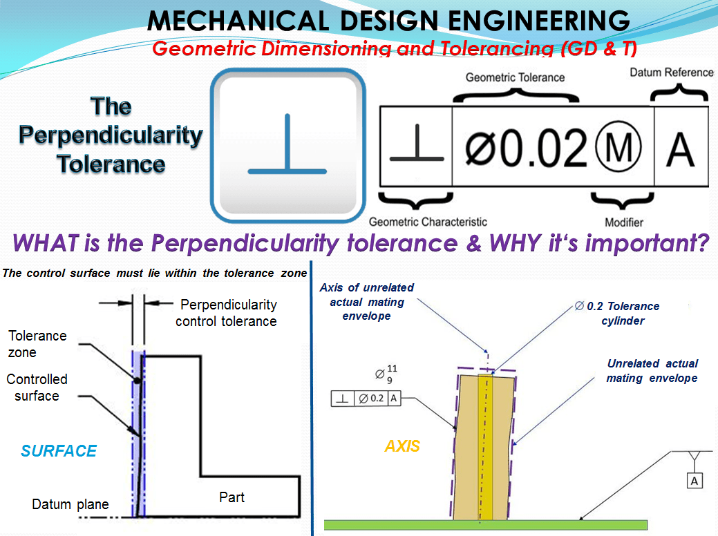
Symbol: The symbol of perpendicularity tolerance are 2 lines, one vertical and one horizontal with the bottom end point of the vertical line connected with the middle point of horizontal line (as shown in figure 1.) This symbol is specified in the left compartment of the feature control frame and it is used to describe a perpendicular orientation of one referenced feature to a datum surface or line.

The Tolerance call out – The feature control frame includes the perpendicularity symbol and tolerance value followed by up to 3 datum references, if needed.
How Does It Work? – The perpendicularity is an Orientation Tolerance and the Orientation is a feature’s angular relationship to a DRF (Datum Reference Frame). An orientation tolerance controls this relationship without meddling in location control. Thus, an orientation tolerance is useful for relating one datum feature to another and for refining the orientation of a feature already controlled with a positional tolerance. This is how to apply it:
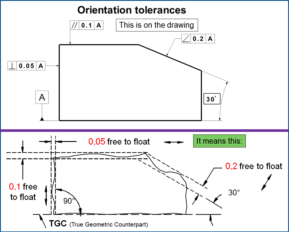
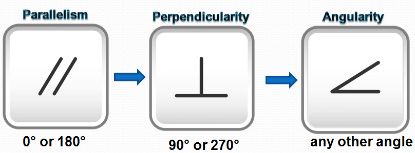
An orientation tolerance is specified using a feature control frame displaying one of the three orientation characteristic symbols. See Fig. 3. The symbol used depends on the basic orientation angle, as follows:
- 0° or 180°—“parallelism” symbol
- 90° or 270°—“perpendicularity” symbol
- any other angle—“angularity” symbol
Applied to a Planar Feature (Including Tangent Plane Application)
Any nominally flat planar feature can be controlled with an orientation tolerance. Fig. 3 shows the tolerance zone bounded by two parallel planes separated by a distance equal to the tolerance value. The surface itself shall be contained between the two parallel planes of the tolerance zone. Form deviations including bumps, depressions, or waviness in the surface could prevent its containment. Thus, an orientation tolerance applied to a plane also controls flatness exactly the same as an equal flatness tolerance. In a mating interface, however, depressions in the surface may be inconsequential. After all, only the surface’s three highest points are likely to contact the mating face (assuming the mating face is perfectly flat). Here, we may want to focus the orientation control on only the three highest or tangent points, excluding all other points on the surface from the tolerance. We do this by adding the “tangent plane” symbol (a circled T) after the tolerance value in the feature control frame. See Fig. 4.

Now, only the perfect plane constructed tangent to the surface’s three highest points shall be contained within the tolerance zone. Since it’s acceptable for lower surface points to lie outside the zone, there’s no flatness control. The validity of “tangent plane” orientation control depends on the surface having exactly 3 noncolinear points that rise above the rest, allowing construction of exactly one tangent plane. Any other condition allows multiple candidate tangent planes to be constructed—a catastrophe not addressed by any standard. The method also assumes the mating face will be perfectly flat. If it too has 3 outstanding points, it’s unlikely that contact will occur in either surface’s tangent plane. So be careful with the “tangent plane” symbol.
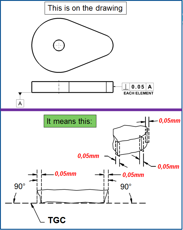
Applied to Line Elements – Where a profiled surface performs a critical function, it’s sometimes necessary to control its orientation to a DRF. For the cam surface shown in Fig. 5, the 3-D control imposed by a parallel-planes tolerance zone is inappropriate because the surface isn’t supposed to be flat. Here, we want to focus the orientation tolerance only on individual cross sections of the surface, one at a time. We do this by adding a note such as EACH ELEMENT or EACH RADIAL ELEMENT adjacent to the orientation feature control frame. This specifies a tolerance zone plane containing a tolerance zone bounded by 2 parallel lines separated by a distance equal to the tolerance value. As the tolerance zone plane sweeps the entire surface, the
surface’s intersection with the plane shall everywhere be contained within the tolerance zone (between the 2 lines). Within the plane, the tolerance zone’s location may adjust continuously to the part surface while sweeping, but its orientation shall remain fixed at the basic angle relative to the DRF. This type of 2-D control allows unlimited surface undulation in only one direction.
Of a Surface Constructed About a Datum Axis—The note EACH RADIAL ELEMENT adjacent to the feature control frame means the tolerance zone plane shall sweep radially about a datum axis, always containing that axis. If the orienting (primary) datum doesn’t provide an axis of revolution for the tolerance zone plane, a secondary datum axis shall be referenced. Note that within the rotating tolerance zone plane, the tolerance zone’s location may adjust continuously.
Of a Profiled Surface—Where only a primary datum is referenced, as in Fig. 5, the tolerance zone plane shall sweep all around the part, always basically oriented to the datum, and always normal (perpendicular) to the controlled surface at each location. Where a secondary datum is referenced, the tolerance zone plane shall instead remain basically oriented to the complete DRF as it sweeps.
Tolerated geometry elements – Datum Reference Frame (DRF) Displacement:
The requirement for maximum contact between a planar surface and its nonsize TGC should yield a unique fit. Likewise, an actual mating envelope’s maximum expansion within an internal feature of size or its contraction about an external feature of size ought to assure a repeatable fit. Each of those types of TGCs should always achieve a unique and repeatable orientation and location relative to its datum feature. Conversely, a fixed-size TGC is not fitted to the datum feature, and need not even contact the datum feature surface(s). Rather than achieving a unique and repeatable fit, the fixed-size TGC can achieve a variety of orientations and/or locations relative to its datum feature, as shown in Fig. 6.
This effect, called datum reference frame (DRF) displacement, is considered a virtue, not a bug, since it emulates the variety of assembly relationships achievable between potential mating parts. Usually, a looser fit between two mating parts eases assembly. You may have experienced situations where screws can’t seem to find their holes until you jiggle the parts around a little, then the screws drop right through. Where a designer can maximize the assembly clearances between piloting features, those clearances can be exploited to allow greater tolerances for such secondary features as screw holes. This may reduce manufacturing costs without harming assemblability.
Tolerance Zone
A tolerance zone with Perpendicularity can be defined by two parallel plane perpendicular to a datum plane, datum axis, or axis which is within where the surface of the feature must lie. The difference is that perpendicularity specifies a 90-degree angle between features while parallelism defines two features that must remain parallel to each other. LMC or MMC can apply to feature of size. Therefore Tolerance zone for perpendicularity can have 2 specific definitions according to the type of reference used, namely Surface or Axis.
Surface =Two parallel planes or lines which are oriented perpendicular to the datum feature or surface. The planes are held perpendicular to the datum, but only ensure that the entire feature falls into the tolerance zone.
Remember: Perpendicularity does not directly control the angle of the referenced surface; it controls the envelope (like flatness) where the surface needs to be.
Axis = A cylinder surrounding a referenced theoretical axis which is directly perpendicular to the datum feature. The tolerance zone is the diameter of this symbol in which the central axis of the measured feature must lie.

When the Perpendicularity tolerance is used
As described earlier, the use of perpendicularity depends of the chosen reference type.
Surface: = Whenever two surfaces needing a constant 90° angle, Perpendicularity is effective. Flange bearings and critical square edges usually reference it. Perpendicularity is also commonly called out on the corners of cylinders where the flat bottom must be perpendicular with the curved sides.
Axis: = Perpendicularity is very commonly called out on the center axis of a hole. Almost always, your hole needs to be perpendicular to the surface it is drilled into. When this is the case, it is called out alongside MMC to ensure that if a pin or bolt needs to be inserted into this hole, the part can enter the whole perpendicular at and always fit in. See example 2 for this explanation.
Example 1 – Surface Perpendicularity
The edge of a stopping block for a rail must form a 90° to ensure proper mating contact takes place. The base of the block is will be our datum and the face where the stopping block makes contact is our referenced surface. To ensure that this face is always perpendicular and flat to make good contact, you would need to both tightly control the angle and the dimensional width of the part.
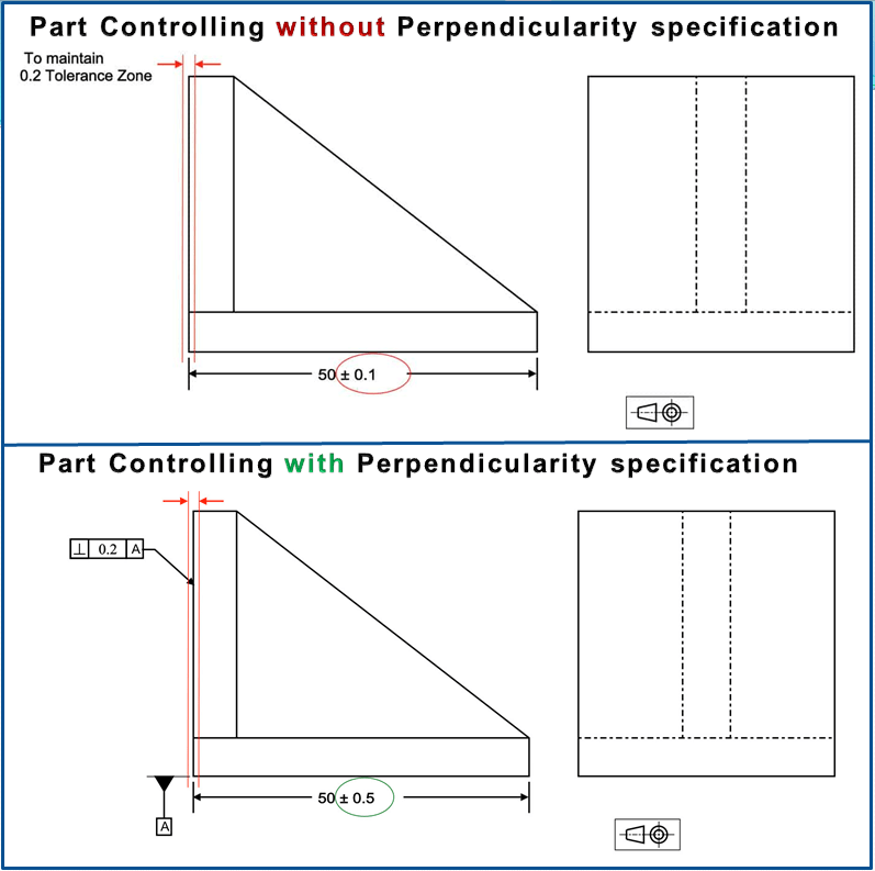
With perpendicularity, you can open up the width dimension and control the face’s angle containing the part very tightly. Your tolerance zone remains the same, but your part is now easier to control and fabricate.
Example 2 – Axis Perpendicularity with MMC.
If you have a critical hole feature that needs to remain parallel to the surface that is formed into, perpendicularity can be called out to ensure that the hole is straight. In this example, a bolt hole is specified to remain perpendicular to its surface.
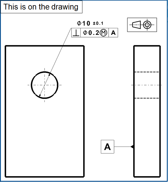
Without an MMC callout, you would need to control just the center axis of the hole and measure it to ensure it is at 90° to the bottom surface. However, when MMC is called out on the print, you are controlling both the size and the orientation of the hole. You now can check both tolerances using a functional gauge with the following dimensions:
Formula for a perpendicularity functional gauge:
- Gauge Ø (pin gauge) = Min hole Ø – Perpendicularity Tolerance
- Gauge Ø = 9.9 – 0.2 = 9.7
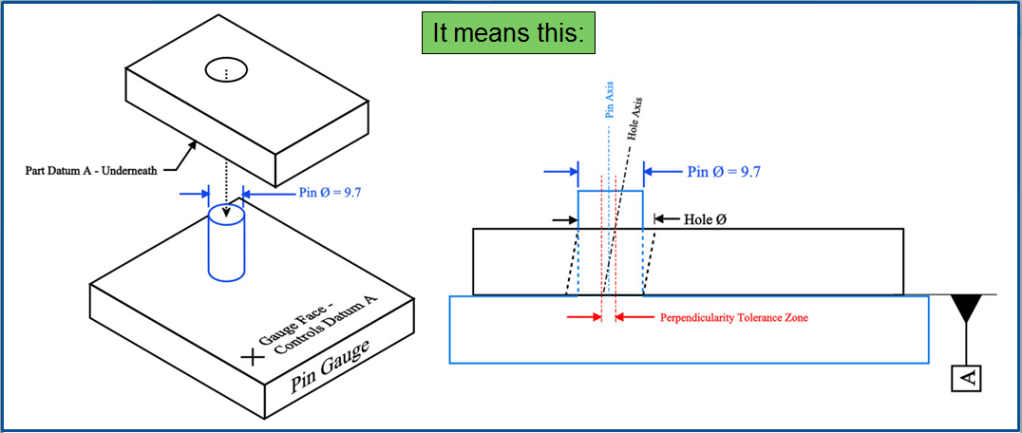
Hole Ø + Hole Perpendicularity > 9.7 (Pin Ø) to be in spec.
Due to the Max Material Condition callout, if you have a hole that is larger than the MMC of 9.9 you will have bonus tolerance that can be added on to your perpendicularity. (According to print Hole Ø cannot be above 10.1 though)
Example 3 – Axis Perpendicularity with MMC & BONUS Tolerance
In the example below – similar with example 2 – the hole is at the least material condition (largest hole size) with the hole at the LMC, your bonus tolerance that can be added to the perpendicularity is calculated as follows:
- Bonus Tolerance = Actual Part Size – Max Material Condition
- Bonus Tolerance = 10.1 – 9.9 = 0.2
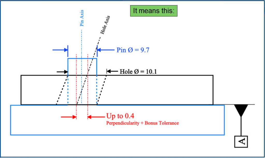
Adding this bonus tolerance to your perpendicularity means your “gauged” perpendicularity tolerance can go up to 0.4 when the part is at its largest diameter.
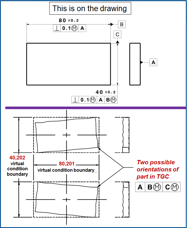
Example 4 – Virtual Condition Boundary for Orientation
For two mating features of size, the perfect form boundaries can only assure assemblability in the absence of any orientation or location restraint between the two features—that is, the features are free-floating relative to each other. In Fig. 13, I’ve taken the simple example of a pin fitting into a hole, and added a large flange around each part. I’ve also stipulated that the two flanges shall bolt together and make full contact. This introduces an orientation restraint between the two mating features. When the flange faces are bolted together tightly, the pin and the hole must each be very square to their respective flange faces. Though the pin and the hole might each respect their MMC boundaries of perfect form, nothing prevents those boundaries from being badly skewed to each other. We can solve that by taking the envelope principle one step further. An orientation tolerance applied to a feature of size, modified to MMC or LMC, establishes a virtual condition boundary beyond which the feature’s surface(s) shall not encroach. For details on how to apply an orientation tolerance, see section Fig 3 above.
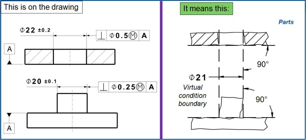
In addition to perfect form, this new boundary has perfect orientation in all applicable degrees of freedom relative to any datum feature(s) we select. A single feature of size can be subject to multiple virtual condition boundaries.
For each example part in Fig. 13, I’ve restrained the virtual condition boundary perpendicular to the flange face. The lower portion of Fig. 13 shows how matability is assured for any part having a pin that can fit inside its Ø21 MMC virtual condition boundary and any part having a hole that can contain its Ø21 MMC virtual condition boundary.
Example 5 – Frequent Application examples
To tolerate perpendicularity, a single reference element is usually sufficient. Fig. 14, shows some frequent cases:
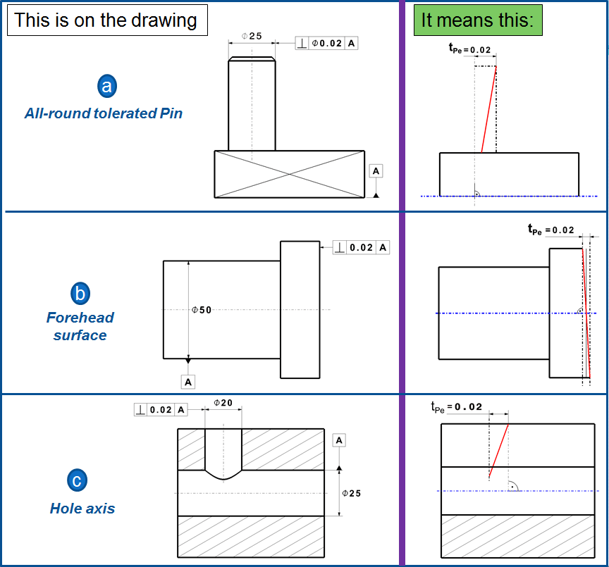
a) tolerated pin: The perpendicularity deviation from the right angles between the axis of a guiding pin and the baseplate is limited to 0.2mm all around. The tolerance zone is a tube of Ø0.02mm which remains exactly in normal direction to datum A; it also defines the Straightness of the axis.
b) forehead surface: The forehead surfaces of the bolt must be 0.02mm perpendicular to the axis A. The tolerance zone limits in the same time the Flatness of the Forehead surface. For the measurement, the workpiece , for example with the pin (a), can be clamped in a measuring chuck, and the forehead surface can be perpendicularly scanned with a measuring clock.
c) 2 hole axis: The upper bore of a socket piece is tolerated vs. the transversal bore. The tolerance zone can only be defined by 2 planes, meaning that the perpendicularity indicates nothing about it, to what extend both axis intersects with each other (otherwise a symmetry tolerance would be suitable)
Gauging / Measurement
Surface: Perpendicularity is measured using a height gauge, similar to flatness, however, the gauge (or part) is locked to a 90° datum to measure how perpendicular the surface is. The entire surface has to be measured if it is a flat feature.
Axis: To ensure that a part or feature is axially perpendicular, Maximum material condition is most often called out on axis perpendicularity to allow easy measurement with a gauge. This allows it to be designed for either a negative (hole) or positive (pin) feature and can take into account a bonus tolerance.* (see the Note below)

As shown in Fig 15 On axis measurement goes like this:
Gauge size for an internal feature (like a hole): Gauge Ø (pin gauge)= Min Ø of hole (MMC) – Perpendicularity Tolerance
Gauge size for an external feature (like a pin): Gauge Ø (hole gauge) = Max Ø of pin (MMC) + Perpendicularity Tolerance
*Note on Bonus Tolerance: When a functional gauge is used for Perpendicularity, any difference the actual feature size is from the maximum material condition would be a bonus tolerance. The goal of a maximum material condition callout is to ensure that when the part is in its worst tolerances, the orientation and size of the hole/pin will always assemble together. This means that if you make a pin smaller, you make more bonus tolerance for yourself. This bonus can be added to the GD&T tolerance and would widen the perpendicularity tolerance.
Bonus Tolerance = Difference between MMC & Actual condition (See Example 3 above)
Confused yet? No worries! I will share more in details about this with a new article about Maximum Material Condition.
Relation to Other GD&T Symbols
Surface:
Perpendicularity is a specific form of Angularity at 90°. All of the orientation symbols (Angularity, Parallelism, and Perpendicularity) all call out the particular feature envelope referenced to a datum. The Perpendicular Symbol is also closely related to flatness when referenced/measured surface is a surface plane. When you call out Perpendicularity, flatness is implied (you are measuring a surface variation between two parallel planes = Flatness) Perpendicularity is always measured with respect to a datum, where flatness is not.
Axis:

Perpendicularity is closely related to all the other orientation GD&T symbols when called on an axis. The tolerance zone now refers to the uniformity and cylindrical envelope of a central axis. Perpendicularity and Parallelism can be called out on holes and cylindrical pins, often with MMC added.
Final Notes
Very Common: Perpendicularity is very common in its surface and axis form. You will see this commonly on many mechanical engineering drawings.
Features of Size: Perpendicularity will most likely have an MMC or LMC callout if gauge control is used in a production environment. It allows both size and orientation to be measured quickly on the line, as opposed to having to measure perpendicularity with a CMM. (Coordinate-Measuring Machine).
Axis Controls: Straightness, Axis Angularity, Axis Parallelism, True Position, and Axis Perpendicularity can all be called out to control a center axis. Usually, when this is a case in a production environment, MMC is also called out so that a functional gauge can be used. However, the only callouts with this case that you would see commonly are perpendicularity and straightness.

Leave a comment