
When you create a part as CAD data sure you can create a beautiful animation and virtually your part is perfect. But if you also intend to produce it, then without using GD & T for functional geometrical elements your CAD work remain only a virtual concept of something. It won´t work for real. Therefore you MUST use GD & T rules and define the final concept of your part. Obviously the first elements that you must define are the dimensional tolerances for the functional elements. Then you must continue with the geometrical tolerances of Form and Orientation. It can happen that those Orientation tolerances are not that often used like those of Form, but they are all very important in many cases. About all Form tolerances I´ve already posted how each of these work (in case you want to read about them, just scroll back on my blog and you´ll find all).
In this post I contiunue with the Orientation concepts. In the category of Orientation tolerances there are 3 sub-groups such as: Direction, Location and RunOut. Each of these 3 sub-group have their own sub-groups too. I will be talking about all of them , but for now let´s have a look at the Sub-Group : Direction which is made of 3 tolerance types: Parallelism, Perpendicularity and Angularity.
I´m gonna start with the PARALLELISM Tolerance. This is a very important tolerance, if not applied correctly you will end up manufacturing something that will not work at all. So be very careful. Let´s explore below how this type of tolerance works.
Parallelism Special Note: –Parallelism actually has two different functions in GD&T depending which reference feature is called out. The normal form or Surface Parallelism is a tolerance that controls parallelism between two surfaces or features. The surface form is controlled similar to flatness with two parallel planes acting as its tolerance zone.
Axis Parallelism is a tolerance that controls how parallel a specific parts central axis needs to be to a datum plane or axis. The axis form is controlled by a cylinder around a theoretical perfectly parallel axis. Parallelism is most commonly called out as surface parallelism. However, be sure to pay attention if it is referencing a central axis because it is different!
In this article, I will discuss more about surface parallelism but be sure to check out my article on Perpendicularity to see how an axis is controlled with GD&T.
Description
Parallelism is the geometrical condition of a surface or center plane equidistant at all points from a datum plane, or an axis. The distance between the parallel lines, or surfaces, is specified by the geometric tolerance zone.
Parallelism can reference a 2D line referenced to another element, but more commonly it relates the orientation of one surface plane parallel to another datum plane in a 3-Dimensional tolerance zone. The tolerance indirectly controls the 0° angle between the parts by controlling where the surface can lie based on the datum.
Note: Parallelism does not control the angle of the referenced feature, but only creates an envelope in which the feature must lie.
It is important to determine what the reference feature is (surface or axis) and then what is acting as the datum (surface or axis) to determine how the parallelism is to be controlled. This is an important feature for a numerous mechanical elements such as spacers, guidings, gearing-boxes and many more.
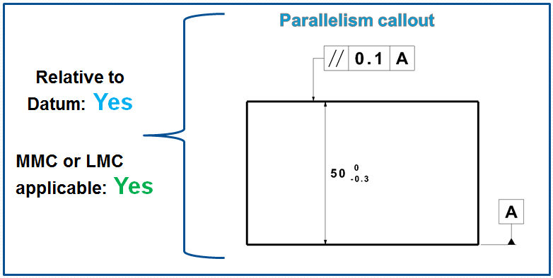
Symbol: -The symbol of parallelism tolerance are 2 parallel slash lines (as shown in figure 1.) This symbol is specified in the left compartment of the feature control frame and it is used to describe a parallel orientation of one referenced feature to a datum surface or line.

NOTE: The rules applied for parallelism tolerance are also applied to the other direction tolerances (perpendicularity & angularity) and partially to location tolerances (position, concentricity & symmetry) as well.
The Tolerance call out: – The feature control frame includes the parallelism symbol and tolerance value followed by up to 3 datum references, if needed.
How Does It Work? – The parallelism is an Orientation Tolerance and the Orientation is a feature’s angular relationship to a DRF (Datum Reference Frame). An orientation tolerance controls this relationship without meddling in location control. Thus, an orientation tolerance is useful for relating one datum feature to another and for refining the orientation of a feature already controlled with a positional tolerance. This is how to apply it:
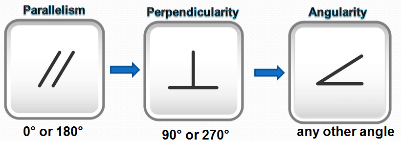
An orientation tolerance is specified using a feature control frame displaying one of the three orientation characteristic symbols. See Fig. 3. The symbol used depends on the basic orientation angle, as follows:
- 0° or 180°—“parallelism” symbol
- 90° or 270°—“perpendicularity” symbol
- any other angle—“angularity” symbol
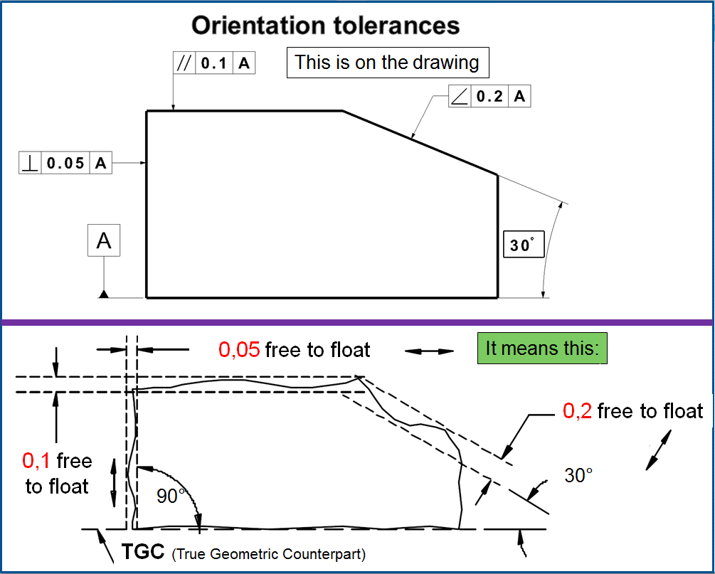
All three symbols work exactly the same. The only difference is that where the “angularity” symbol is used, a basic angle shall be explicitly specified. Where the “parallelism” or “perpendicularity” symbol is used, the basic angle is implied by a drawing view that shows the parallel or perpendicular relationship. Though a single generic “orientation” symbol has been proposed repeatedly, most users prefer separate symbols for parallelism and perpendicularity because each tells the whole story at a glance.
Tolerated geometry elements – Orientation control requires a DRF (Datum Reference Frame). A primary datum plane or axis always establishes rotation about two axes of the DRF and is usually the only datum reference needed for orientation control. There are cases where it’s necessary to establish rotation about the 3rd axis as well and a secondary datum reference is needed. Sometimes, a secondary datum is needed to orient and/or locate a tolerance zone plane for controlling line elements of a feature. In other cases, hyphenated co-datums may be used to arrest rotation. Since all three rotational degrees of freedom can be arrested with just two datums, a tertiary datum is usually meaningless and confusing.
Tolerance zone
Limit deviation is the two parallel planes or lines which are oriented parallel to the datum feature or surface. All points that are on the referenced feature must in the tolerance zone.
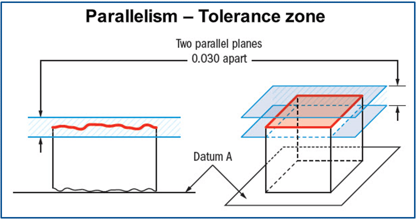
Remember: Parallelism does not directly control the angle of the referenced surface; it controls the envelope (like flatness) where the surface needs to be. The goal is to ensure all points are within a specified tolerance distance away from their corresponding datum points.
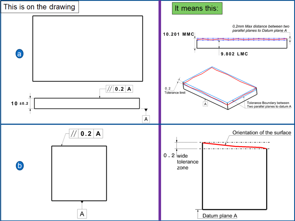
In Fig. 5 below The surface of the part must lie between two parallel planes 0.2mm apart versus the bottom surface marked as reference datum plane A. The surface of the part must be within specified tolerance limit at a maximum 0,2mm between 2 parallel planes to datum A.
In Fig. 6 The surface of the part must lie between two parallel planes 0.2mm apart around the axis which are parallel to the datum plane A. The surface of the part must be within specified tolerance limit.

The feature axis must lie within 0.2mm diameter of cylindrical zone parallel to the datum axis A. The feature axis must be within specified tolerance limit.
When the Parallelism tolerance is used?
Whenever two surfaces or features need to work in sync with each other and constant distance must be maintained, parallelism is effective. Whenever you have a part that must always fit nicely between two planes that need to reference each other, it comes in handy. Even though surface parallelism seems to ensure that a flat surface is mating with another flat surface, it can also be applied to two sides of a hole or cylinder to avoid a taper. Any part with two critical flat surfaces such as gears would call out parallelism.

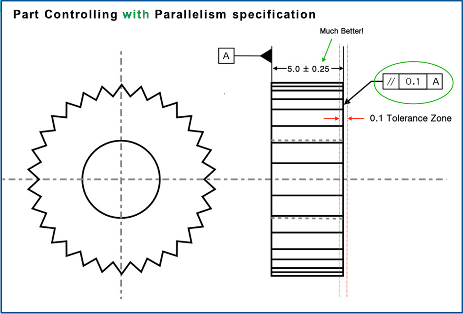
Parallelism Example of use: A gear has to maintain constant axial load on both faces. To ensure even contact one side of the gear is held parallel to the other side. To do this without parallelism, (as shown in fig.8) the gear width would have to be tightly controlled, which could be very difficult to do.

With parallelism, (as shown in Fig. 9) you can open up the dimension of the gear and control the faces without rejecting good gears.
Examples with Holes as Reference Element
Figure 10, 11 & 12 shows a simplified workpart. Practically such tolerance specification often comes for example on connection rods, levers or gearboxes with 2 drive shafts. A hole in this case determines the tolerance zone; the reference datum in therefore placed on the hole dimension line. For a correct interpretation is recommended to take the following approach:
- Which type of Tolerance is it (recognizable after the Symbol)
- Which element is tolerated (A direct or a derived feature)
- Where the reference is (on a surface or on axis, or others)
- How does the Tolerance zone looks like (form, links to references)
- Which extreme position or forms can the tolerated element take? (decisive for functionality role)
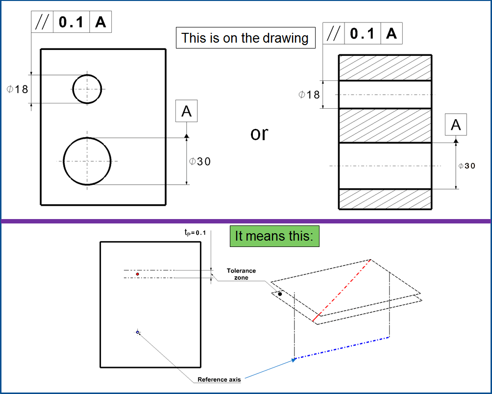
Example 1.- Partially tolerated hole
According to the 5 questions approach mentioned above, in this example the specified tolerance is parallelism (1), of the axis of the small hole (2), the reference datum A is the axis of the big hole (3). The tolerance zone lies perpendicularly to the tolerance arrow (4). In case that before the tolerance value of 0.1 there is no diameter sign (Ø) then the tolerance zone is defined by 2 parallel planes at a distance of tP =0.1mm. Alternatively according to the rule, the tolerance can be specified in the front or side view. The form of the tolerance zone means that the toleranced axis is only defined in its inclination related to the reference (5), but not in the angle, meaning that it can be skewed to the reference. This will be restricted at best through a general tolerance. If such tolerancing, functionally makes sense then it stands there.
Example 2. – Hole tolerancing in 2 directions
Additionally to the initial tolerance specified for the direct geometrical feature (as shown at the previous example) there is a second parallelism tolerance tP=0,2mm specified, which restricts the axis too. This is a good example which shows how important the rule is to indicate the tolerance zone as perpendicular to the tolerance arrow. The datum reference is therefore entered only once. The reference triangle of the datum entered on the Ø 20 dimension arrow defines the reference axis, which can be used in all directions. The tolerance zone has in this case the shape of a “rectangular pipe”. But that only pays for the fact that the measurement has to be carried out in two directions that are perpendicular to each other.

Example 3. – Hole tolerancing in all directions
If the diameter symbol (Ø) is specified before the tolerance value, this means that the tolerance zone has a cylindrical pipe shape and restricts the tolerated axis in all directions in the same time also its straightness.

The Axis checking: the reference axis is the axis of the ideal free-play adjacent element, in the examples above (fig. 10, 11 and 12) this being the axis of the pen cylinder. The actual axis, on the other hand, is derived from individual cross-sections. Practically such a measurement is often not feasible and from the function also not useful. Instead a free-play test mandrel is inserted into the tolerated hole and the hole position is measured in relation with this reference mandrel. This is how an axle or a bolt will later sit in this bore.
Examples of Parallelism tolerance on planar reference elements
The following sketch representations shown in fig. 13 are frequent cases in practice.
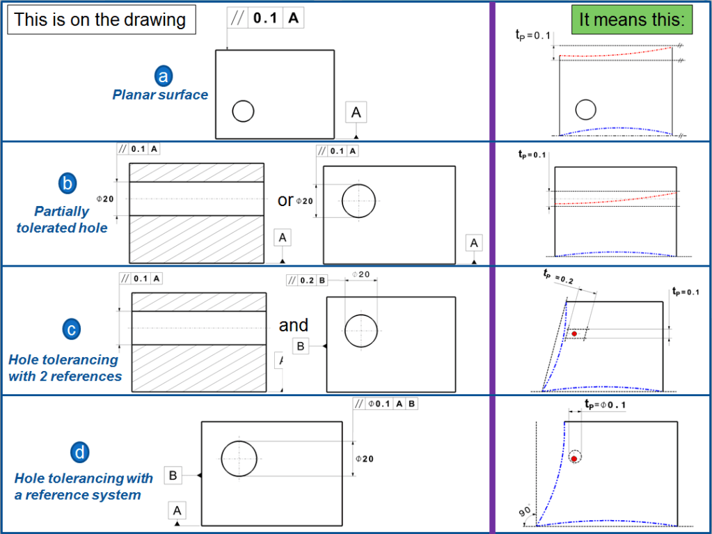
Example 4 -a) Planar surface parallelism
The tolerance zone is restricted 2 planes at at distance of 0,1mm located parallel to the reference datum.
Example 4 -b) Partially tolerated hole
Here the tolerance zone is also restricted by 2 planes but the single datum reference A offers no possibility to restrict the direction of the hole axis other than in the height direction. The tolerance can therefore be optionally inserted in one of the views (as shown in fig. 10)
Example 4 -c) Partially tolerated hole
In order to fix a hole also sidewise a second datum B must be inserted. The entry follows the rule ” The tolerance zone lies perpendicularly to Tolerance arrow”. Both datum references, both independent from each other, meaning that they do not create a system and therefore they also are not placed at an exact angle one vs. the other.
Example 4 –d) Hole tolerancing with a reference system:
The tolerance zone in this case is tubular shaped. Its definition requires a reference system with 2 reference datums or but only one reference axis. (see fig. 12)
The need of reference systems.
The tolerancing shown in fig. 10, 11 and 12 looks clear and explicit, but in realty is not really exactly how things happen. “The Tolerance zone lies perpendicularly to tolerance arrow” but orthogonal too, meaning that it is measured in the direction of the tolerance arrow. Is this now the direction perpendicular to the lower surface or is parallel to a sidewise surface, and if so to which one?
The diferences in measurement results might be small but they exist. That´s why in case of doubts, a secundary datum reference is required mainly for irregular shaped workpieces. (acc. to DIN EN ISO 1101:2006)

Example 5 – a) Bottom surface as secondary reference
In fig. 14- a. the bottom surface is used as secondary reference element, as datum B. The difficulty is to make datum A and datum B parallel with each other (not perpendicular). The primary datum A defines a “length” axis. When the work-piece is included in this definition (for instance by means of a free-play mandrel) it still has 2 freedom degrees, namely the rotation around datum A and the translation along the length of datum A. The latter is useless for parallelism definition and therefore will no be further considered. When the datum references define a reference system, meaning that the tolerance frames are made up of separate compartments, they are positioned at exact angles between each other. The datum B is consequently a surface which is parallel to datum A and the direct reference element B , in this case the bottom surface, is pushed along the datum A. (similar as shown in fig, 14-b). Like that the direction of B and tolerance zone is clearly defined.
Note: This corresponds somehow to the effect of a tertiary reference datum C. The difficulty is when the reference surface is a convex one, meaning its “wobbled”. That´s why it is recommended to specify to reference positions or also to mention the NC (Numerical Command) in the tolerance frame.
Example 5 – b) Sidewise surface as secondary reference
Fig. 14 – b – uses the left side surface as secondary reference B. This means in no way, that the tolerated axis also must be parallel to B. (additionally a second tolerance entry is necessary like shown in fig. 11). The tolerance zone in this case lies parallel to datum A and perpendicular to datum B (fig. 14 -b -meaning).
Parallelism dependence between direction and dimension tolerances.
A direction tolerance restricts only the direction of the tolerated element. Its location, in contrast, often results from dimensioning which was omitted from the figures I´ve just showed until now.
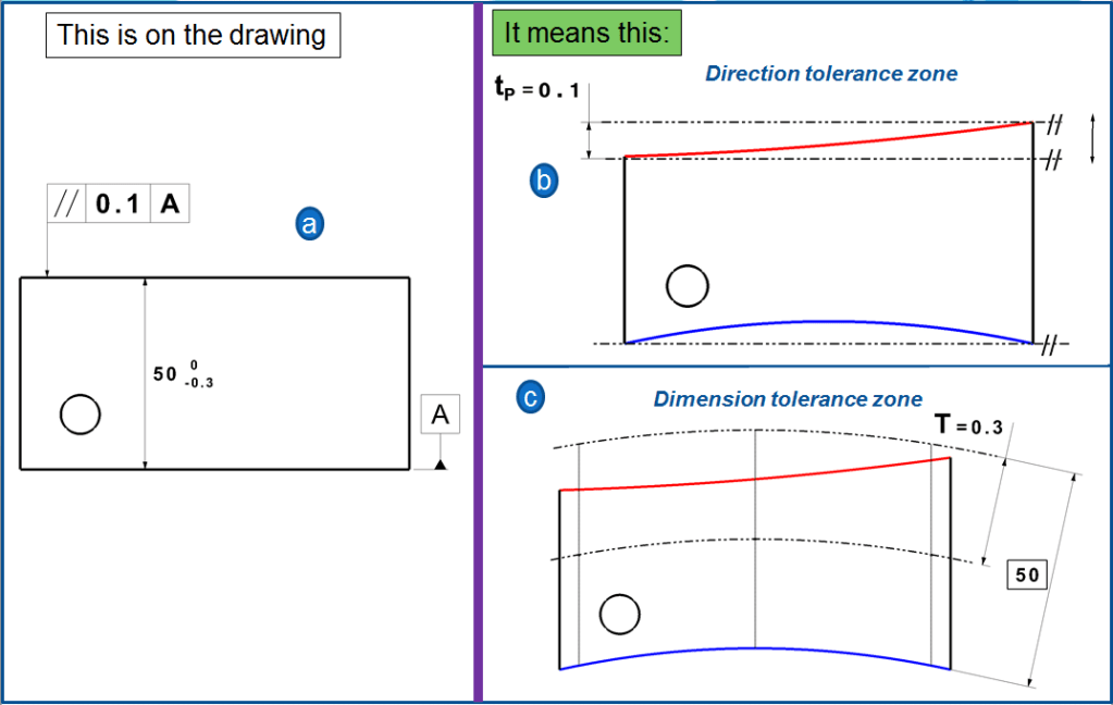
Example 6 – Parallelism dependence on direction and dimension
In fig. 15 I show this completely (corresponding to fig. 13-a). The tolerance zone for parallelism (fig, 15-b) is slidable, only its direction is tied through the datum reference (here defined acc. to the Least Material Condition). The dimension tolerance is therefore measured independently. As long as the dimension arrow doesn´t have a origin circle at one end (which is here advisable), then it will be measured with 2 points-procedure. Like that the tolerance zone not in a straight line (fig. 15-c) and both the measurement for dimension and for the direction are not direct comparable.
However, every dimensional tolerance limits the direction tolerance too. With this the following rule applies:
Direction and dimension tolerancing: “The instant entry for a dimension and a direction tolerance for a geometric element it mostly makes sense if the direction tolerance is smaller than the dimension tolerance.”
Parallelism dependence between direction and form tolerances.
Every direction tolerance close down a straightness tolerance and when a plane is tolerated then also the flatness is. As a rule the following applies:
“In each direction tolerance there is a flat form tolerance included; meaning that the straightness deviation of a tolerated element (perpendicularly measured on tolerance zone) can not be bigger than the the direction tolerance t; Correspondingly this is also valid for flatness deviation of tolerated planes. The additional entry of a Straightness, respectively a flatness tolerance makes therefore sense only when the Form tolerance is smaller than the direction tolerance” (see fig, 16 a and b).
Example 7 – Parallelism dependence between the direction and form.
The tolerance zones (d) show the dependence. The tolerance zone for Flatness is slidable and rotable, which is only slidable for Parallelism. (Incidentally, the flatness tolerance zone does not have to be completely within the parallelism tolerance zone). The entry of a form tolerance of equal size like the direction tolerance (b) is unnecessary, which a still bigger form tolerace (c) is senseless. The latter could never be exploited, as the toleranced form element must be between two planes at a distance of 0.1 mm.
Critical consideration of the included form tolerances.
Basically, every tolerance should be based on the functional requirements.The parallelism tolerance of a surface indicates in which direction the neighboring component to it lies. The Flatness tolerance indicates something about how well it rest on it. In fig. 17 the upper surface has at a) and b) the same deviation dP = 0,1mm vs. the datum reference. It indeed, it appears to be completely “parallel” to the outside (as long as the counterpart flat is) and at b) is however “crooked”.

At a) there is a pure form deviation. If the reference surface and the tolerated element on the workpiece (a) is inverted (c), then the parallelisms deviation becomes 0, because the previous reference surface is now pretty flat. As a general statement the following worth considering arguments about Parallelism tolerance must be mentioned:
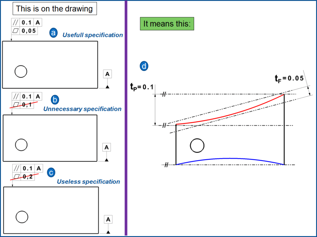
- If the parallelism tolerance is exceeded, then that alone says nothing about the way in which the manufacturing process is to be corrected. That speaks in favor of dividing the form and position in individual tolerances (ISO 1101 doesn´t do that)
- Sometimes you want to tolerate the direction of a surface tightly, as it is represented by an adjacent test plate, but provide the Flatness with a greater tolerance than that for parallelism (for example because of the risk of warpage). With ISO 1101 this is not possible (instead is possible with ASM 94). A tolerance entry as shown in fig. 16 c would be conceivable with the note “only direction” in the tolerance entry frame for parallelism.
- The functionality of a geometric element often means that its form deviations remain in the same order of magnitude as the positional deviations. Then specifying a single tolerance is easier than specifying two. At increased demands for the Form a separation is however possible (fig. 16-a)
- Sometimes a borderline or a workpiece is requested, meaning its extreme extension towards the maximum material side (for example: gripping devices) or towards the minimum material side (for example: machining allowance). Their determination is easier if the form deviations remain within the position tolerance, like established by ISO 1101.
Tolerance of line elements in a surface
With DIN EN ISO 1101: 2006 the direction of simple bent surfaces can be also tolerated fig. 18 -a. Under the tolerance frame is mentioned LE (Line Element).
Example 8 – Parallelism tolerance of line elements.
As with straightness within surfaces, the tolerance frame should be in the view where the straight lines to be checked are visible, meaning to lie parallel to the drawing plane. The tolerance zones, are many arbitrary strips of 0,1mm height. They are each parallel to datum B, their tolerance limits are parallel to datum A. The measurement succeeds perpendicular to datum A in the direction of the tolerance arrow.
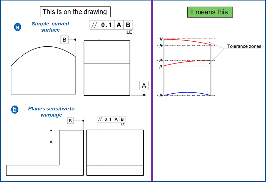
This tolerancing is also applicable on surfaces, fig. 18 -b. The thin lower base tends to warp. That´s why in the parallelism the Flatness is not included, but only the Straightness of arbitrary single lines which run parallel to datum B.
Gauging / Measurement.
Parallelism is quite simple to measure. Like flatness, a gauge is run across the reference surface or feature. However, unlike flatness, the part is constrained against a granite block or flat plane that acts as the datum surface where it is measured.

Relation to Other GD&T Symbols.
Surface Parallelism
Parallelism is a specific form of angularity only at 0°/180° instead of a called out angle. All the profiles of orientation and are used in the exact same way. All of the orientation symbols (angularity, perpendicularity, and parallelism) all call out the particular feature envelope referenced to a datum.

The Parallel Symbol is also closely related to flatness when referenced/measured surface is flat. When you call out parallelism, flatness is implied (you are measuring a surface variation between two parallel planes = flatness) However the biggest difference is parallelism is measured with respect to a datum, ensuring both the datum and reference feature are always parallel.
Final Notes
Combination of Orientation and Form – Parallelism is very common in its surface form. When dealing with any flat surfaces, flatness may be called out, but parallelism is usually more critical since the relation of surfaces in an assembly is more important.
Max Material Condition with Axis – Straightness, Axis Angularity, Axis Parallelism, and Axis Perpendicularity can all be called out and controlled with a gauge in maximum material condition. However only perpendicularity and straightness are used commonly.

Extremadamente excelente la exposición. Muy didáctica a y nivel profesional.
LikeLiked by 1 person
Muchas gracias.
LikeLike